The 1890s were one of John Browning’s most prolific periods, during which he developed a host of firearms which would never actually see production. Here, we’re lucky enough to be able to examine one of those prototypes that were never produced. Dating from 1892, this rifle departs from Browning’s earlier lever-action rifle designs in a number of interesting ways. Perhaps the most interesting aspect of the design is its use of en bloc clips, instead of the tube magazine traditionally used by Winchester’s repeating rifles. John Browning, and his brother Matthew, filed the patent covering the design in June 1892.
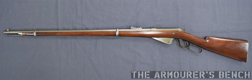
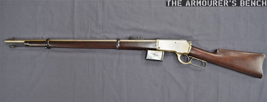
Right side of the rifle, note its ‘musket’ configuration (Matthew Moss)
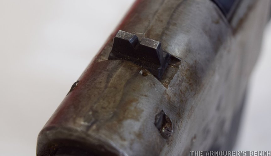
The rifle is in what is typically referred to at the time as a ‘Musket’ configuration, signifying that it is a military long-arm. It has a long 32.5 inch barrel, which is held in place by two barrel bands. Overall the rifle is around 50 inches in length and weighs just over 9lbs. The rifle is chambered in a .30 calibre cartridge, likely the then new .30-40 Krag round given its proposed market. It has a ladder-style rear sight with range graduations from 100 to 1,000 yards.
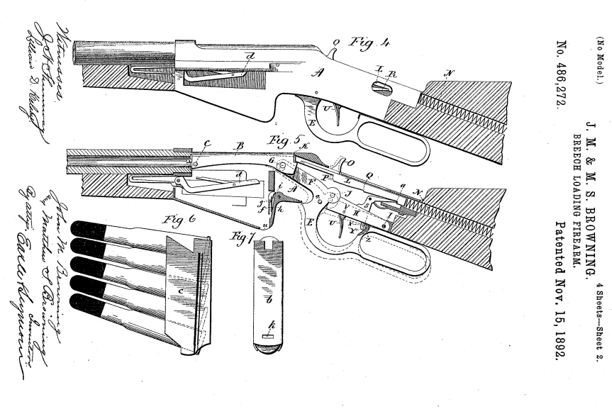
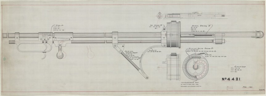
Browning’s patent drawing showing the rifle’s action (US Patent Office)
Okay, let’s take a closer look at the prototype. During the 1890s Browning experimented with a series of magazine systems including an en-bloc clip system. This rifle uses a 5-round magazine which is fed from an en-bloc clip. The idea of an en-bloc clip was relatively new with Ferdinand Mannlicher patenting the idea in the 1880s and using it in his Model 1886 and 1888 rifles. It is unclear if Browning was familiar with Mannlicher’s system but the two are very similar. If you’re unfamiliar with en bloc clips it means that the cartridges are loaded into the weapon in the clip rather than stripped from the clip.
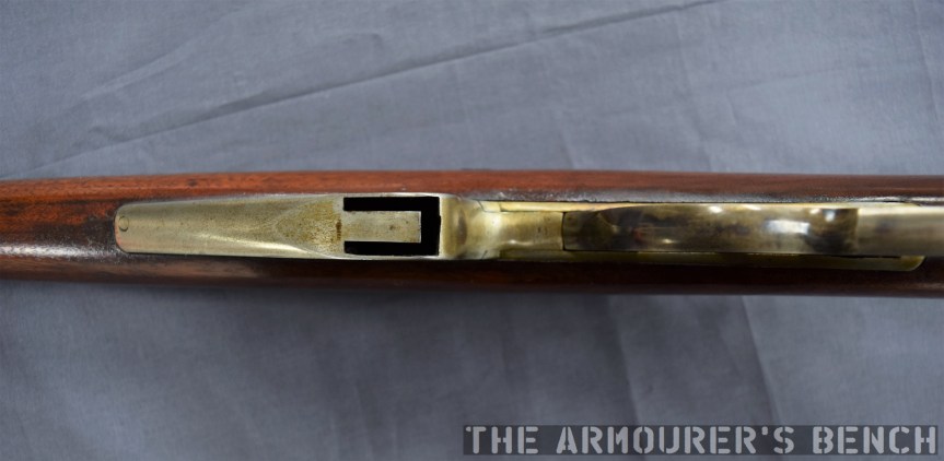
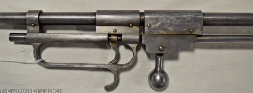
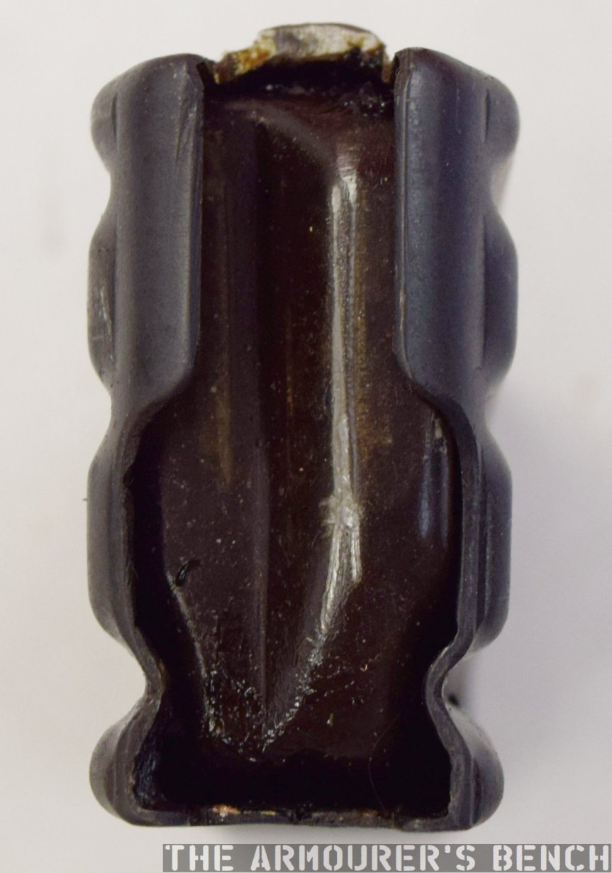
A look at the ejection port for the en-bloc clip (Matthew Moss)
Browning’s prototype holds five rounds in its clip, which from patent drawings we can see was not reversible. Sadly, we don’t have an example of Browning’s clip to examine but his 1892 patent (see above) gives us a good idea of what it would have looked like. It clearly has a cut at the top of the clip which appears to have been used to help guide the round up into the chamber.
Rounds were pushed up into the action by a follower arm which was actuated by a v-spring located at the front of the magazine housing. The bottom of the fixed magazine housing has a cut-out corresponding to the clip to allow it to fall or be pushed clear by a new clip once it was empty.
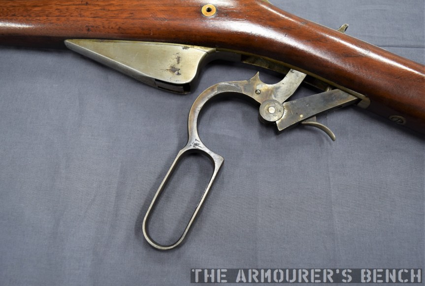
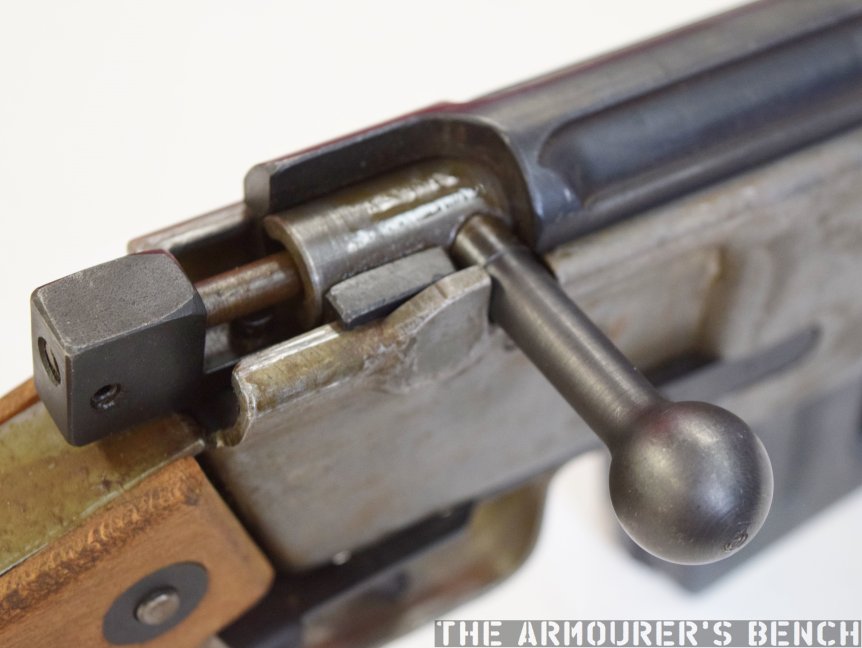
The rifle’s lever fully-forward with its action open and striker cocked (Matthew Moss)
The rifle also departs from the traditional hammer system and uses a striker-fired action. From the patent drawings we can see how the rifle’s striker worked, with a coil spring extending into the stock and a sear holding the striker to the rear. The striker is made up of two pieces with the striker hitting a long firing pin inside the bolt.
The striker has, what the patent refers to as, a ‘thumb piece’ to enable re-cocking and to indicate if its cocked or not. The striker was cocked by the cycling of the lever and held in place by the trigger sear.
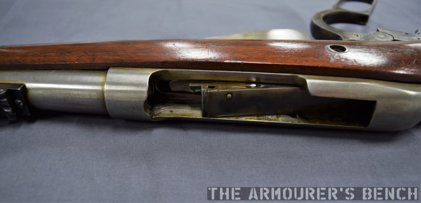
A view inside the action with the bolt partially retracted before it moves down and back into the rifle’s wrist (Matthew Moss)
The lever was held in the close position, preventing out of battery discharges, by what Browning’s patent calls a downward-projecting dog, which projected through a small hole in the trigger assembly link and locked into a catch in the front of the lever loop.
The use of a striker, rather than an exposed hammer, allows the rifle bolt’s travel to be enclosed rather than have the bolt project out of the rear of the receiver, as in previous Winchester lever-actions, we can see that this rifle’s bolt slides back at an angle partially down into the wrist of the stock. This is arguably more ergonomic and potentially helps to prevent ingress of dirt.
The first half of the lever’s travel pulls the bolt to the rear, while the second part cocks the striker. An arm extending from the lever pushed the bolt rearward until the trigger sear was engaged. In order to give the lever enough throw to open the action far enough to allow a round to be loaded the trigger mechanism has to be pivoted out of the action, much like the earlier Winchester 1886.
The bolt has a pair of trunnions which project from the sides of the bolt, these run inside longitudinal grooves either side of the receiver, while the rear of the bolt is free to angle up and down as it cycles. The action is locked by the rear of the bolt secured against the rear of the receiver, rather than with a rising locking bolt.
Left side of the rifle (Matthew Moss)
During the period Browning was also working on other lever action and, even more unusual, so-called pull-apart actions as well as various magazine types including a revolving magazine, stripper-clip box magazines and of course as we’ve already seen a detachable box magazine-fed rifle. The 1890s were a truly prolific period for Browning.
The design was purchased by Winchester and the Brownings’ patent was granted in November 1892. The gun, like many of Browning’s other designs of the period, never saw production. Making this rifle a rare one-of-a-kind prototype. It’s an elegant design and the action is smooth. When Winchester did finally seek to produce a military lever-action they chose another of Browning’s designs which retained his traditional rear-locking bolt, which became the Model 1895.
This rifle is a unique prototype and it was an honour to examine it. It’s now on display at the newly refurbished Cody Firearms Museum at the Buffalo Bill Centre of the West. Our thanks to the museum for allowing us to film items, like this one, from the museum’s collection.
The rifle we’re examining is one of dozens of designs sold by the Brownings to the Winchesters Repeating Arms Company during their long relationship. This design dates from the early 1890s and represents one of Browning’s numerous attempts to move away from the tube magazine-fed designs favoured by Winchester.
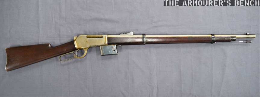
The prototype is based around the lever-actuated vertically sliding locking block patented by Browning in May 1884 and first used by Winchester in the Model 1886. The rifle itself is in the ‘military musket’ configuration with full-length handguards, military sights, a cleaning rod and able to mount a bayonet.
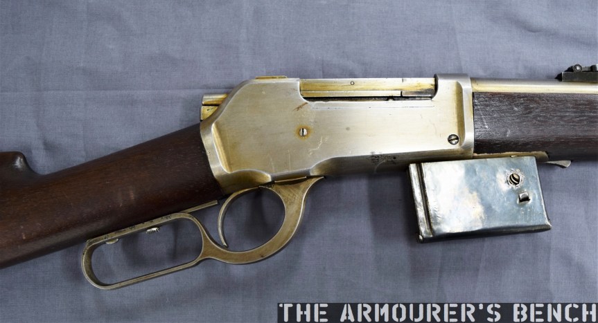
Right side of the rifle (Matthew Moss)
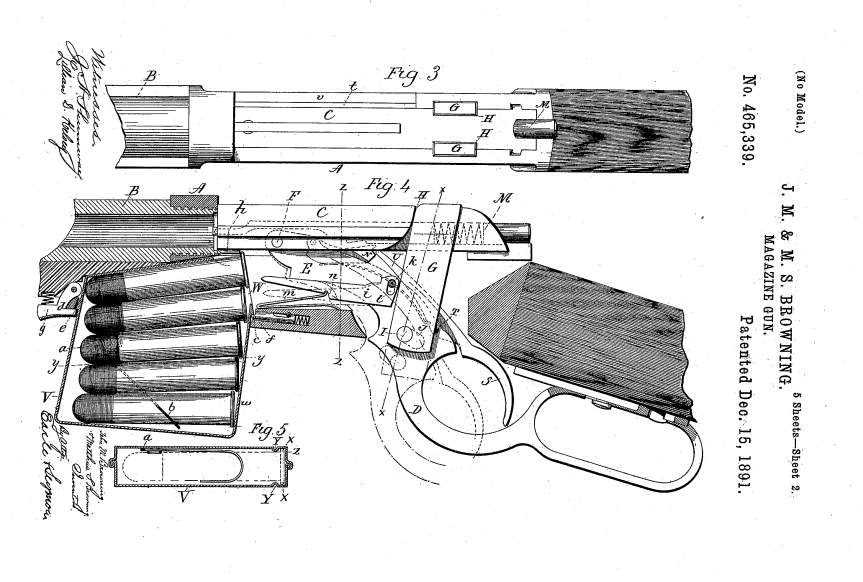
The rifle is chambered in a .45 calibre cartridge, likely .45-70, and weighs just over 9lbs. Browning patented the design of the rifle and magazine in August 1891, with the patent being granted in December (US #465339). It is attributed to John Moses Browning and his younger brother Matthew S. Browning.
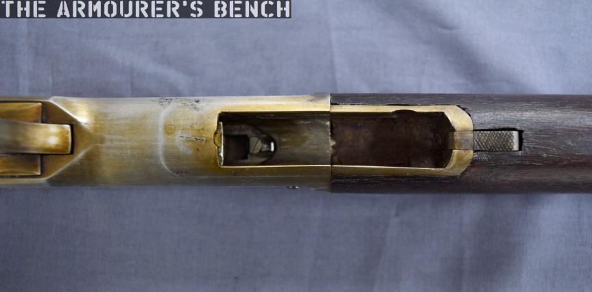
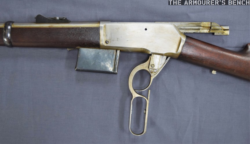
The most interesting feature of the rifle is its detachable box magazine. The magazine is held in place by a spring-loaded catch at the front of the magazine which locks against a tab in the magazine’s wall.
A close up of the magazine well, note the added metal lip of the front of the well, not a part of the receiver (Matthew Moss)
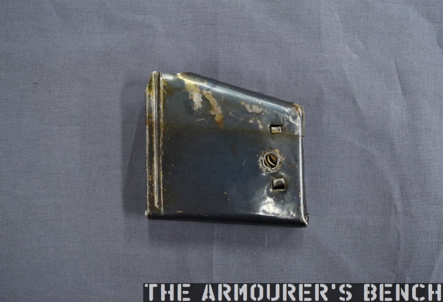
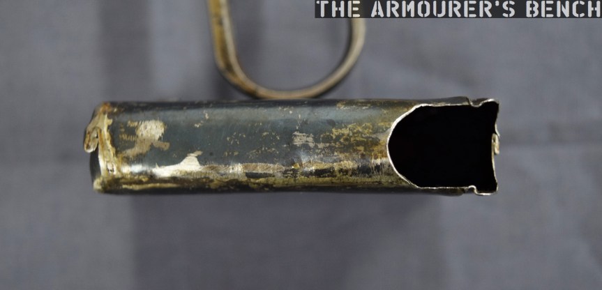
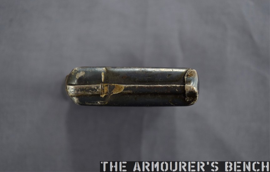
It differs from the box magazines previously developed by James Paris Lee, which Lee begun developing in the mid-1870s (see examples listed below). It’s a simple design with a follower powered by a coil spring. The prototype mag itself is made from pressed metal and is held together with some rough welds. Unlike the magazines we’re familiar with today, the top of the Browning’s magazine is almost entirely enclosed with only a small opening at the rear. The rounds would be loaded nose-first with their rims sliding into the channel at the rear of the magazine.
Close up of the magazine removed from the rifle – right side (Matthew Moss)A view of the top of the magazine with the small opening and notch for the cartridge rime visible (Matthew Moss)
The single-stack magazine appears to hold around five rounds, with Browning’s patent supporting this. The position of the magazine, in front of the action – not below it, is a hint at how it worked. An almost fully enclosed magazine does have its advantages – it would have prevented dirt from entering the mag and it also overcame the need for feed lips which were susceptible to damage, one of the elements which took Lee some time to perfect.
A close up of the front wall of the magazine, note the locking notch (Matthew Moss)
So How Did The Magazine Work?
There is a shoulder on the underside of the bolt which caught the rim of the cartridge which was protruding from the magazine. The bolt pulled the cartridge backwards, out of the magazine and onto a cartridge lifter. As the lever reached its full forward travel the lifter then elevated the round up into line with the breech. When the lever was cycled back again the round was pushed off the lifter and chambered, just as in a normal tube-fed Winchester. As the lever reached the end of its return travel the locking block rose to locked the action.
The Browning’s 1891 patent for the magazine, note ‘h‘ is the shoulder which pulled rounds out of the magazine (US Patent Office)
The prototype has a sliding safety bar that locks the lever and blocks the trigger. The trigger differs from the Model 1886 as it is integrated with the lever. In the photograph below we can see the locking block descended, with the lever forward, and the breech block to the rear with the action open. We can also see the striker assembly at the rear of the bolt. The striker cocks on closing when the lever is returned rearward.
The rifle with its action open, bolt o the rear and lever forward. Note the striker assembly at the rear of the bolt (Matthew Moss)
It’s quite an exposed action, with the entire top of the action open. With the action closed in the photograph below we can see the extractor running along the right side of the bolt.
A close up of the rifle’s receiver which is still ‘in the white’ (Matthew Moss)
It’s clear from the design of the magazine that Browning didn’t intend the rifle to be reloaded with stripper clips, although single loading of the rifle itself (not the magazine) would have been possible. When compared to other contemporary system this would have been somewhat of a disadvantage compared to Lee’s magazine’s later loading with chargers and stripper clips. However, from examination of Browning’s 1891 patent his intention becomes clear, the patent explains that he intended for the magazine itself to be replaced:
“One magazine may be readily removed from the gun and another introduced in its place, so that the person, using the arm may have at hand several magazines to be interchanged as the cartridges from one magazine are exhausted.”
This is a concept that wouldn’t be accepted by militaries for decades. Winchester purchased the rights to the design but this was one of many designs Browning sold the company which never saw production. The design and prototype are fascinating and represent one of Browning’s lesser-known concepts.
Left side profile of the rifle (Matthew Moss)
This rifle is a unique prototype and it was a true honour to examine it. It’s now on display at the newly refurbished Cody Firearms Museum, at the Buffalo Bill Centre of the West. The new museum is phenomenal and well worth a visit. Our thanks to the museum for allowing us to film items, like this one, from the museum’s collection.
Today we’re examining an intriguing firearm with a fascinating history. It is difficult to understate the potential importance of the Curtis Rifle. Despite being designed in Britain in the 1860s the firearm gained more notoriety when it was offered as evidence in a legal battle between the Winchester Repeating Arms company and Francis Bannerman. What makes the firearm most noteworthy, however, is its fundamentally unconventional layout. Designed by William Joseph Curtis in the mid-1860s, it is arguably one of the earliest ‘bullpups’ and almost certainly the first repeating bullpup.
William Curtis’ 1866 ‘bullpup’ rifle, built in 1895 by Winchester (Photo by Matthew Moss, courtesy of the Cody Firearms Museum)
For the purpose of this article it would be wise to first define what a bullpup actually is. It can be defined as a weapon with a somewhat unconventional layout which places the action and magazine behind the weapon’s trigger group. This has the benefit of maintaining a conventional rifle’s barrel length while making the overall length of the rifle more compact.
Bullpup rifles became popular with a number of militaries around the world during the 1970s and 1980s – namely the Austrian Steyr AUG, the French FAMAS and the British SA80, and more recently with rifles from China and Singapore as well as the Tavor series of rifles from Israel.
Thorneycroft, Farquhar and Hill’s 1905 carbine patent (source)
The bullpup, however, dates back much further with some argument to be made for the first firearms to utilise the concept being 19th century percussion target shooting rifles. The earliest military bullpups date to the beginning of the 20thth century, these include a rifles designed by Samuel McClean, the initial designer of the Lewis Gun, patented in 1896 (US #723706), by Major Philip Godsal (US #808282) and a carbine developed by James Baird Thorneycroft in 1901. Thorneycroft subsequently worked with Moubray Gore Farquhar and Arthur Henry Hill to patent a refined version of the carbine in 1905 (US #827893). While the Thorneycroft was tested by the British army it was rejected due to ergonomic and reliability shortcomings.
In 1908 Lieutenant-Colonel Armand-Frédéric Faucon of the Troupes Coloniales (French Colonial Infantry) began developing what he termed a ‘Fusil Équilibré’ or balanced rifle. Faucon patented his concept in France in 1911 (FR #422154) and continued to work on the balanced rifle during World War One, utilising a Meunier A5 semi-automatic rifle in working prototypes. The Faucon-Meunier rifle was tested in 1918 and 1920 but eventually rejected. It would be nearly 45 yeas before the bullpup concept was revisited by a major power. Engineers working at the Royal Small Arms Factory at Enfield and at the British Armament Design Department in the 1940s began to develop designs based around the bullpup concept. (Some of these will hopefully be the focus of future videos!)
William Curtis’ design, however, predates all of these. Patented in Britain on 10th July, 1866, Curtis is listed by the London Gazette as a Civil Engineer. His design is unlike anything that had been seen before. Based on a slide-action with a drum magazine, it was placed over the shoulder – much like a modern shoulder-fired anti-tank weapon.
William Joseph Curtis’ July 1866 patent for ‘Breech actions, sliding breech-block & stocks’ (courtesy of Research Press)
Curtis’ rifle is probably the very first bullpup magazine rifle, one of the earliest to have a drum magazine (an Italian, Marco Antonio Francois Mennons, patented an earlier design for a drum magazine in March 1862, GB #637) and also an early striker-fired design. Clearly a design well ahead of its time and radically unconventional.
This unconventional gun’s designer was born in Islington, London in 1802, as a civil engineer he worked on Britain’s rapidly growing railway network. He died in 1875, placing the development of his rifle nearer the end of his life. With hindsight Curtis’ design clearly had revolutionary potential but it appears that his concept was never taken up. It appears that he only patented his design in the United Kingdom. If not for a corporate lawsuit on another continent, decades later, then it is possible Curtis’ design, like so many others, would have slipped into historical obscurity.
Francis Bannerman vs. the Winchester Repeating Arms Company
In 1890, Francis Bannerman VI, a successful entrepreneur specialising in junk, scrap and later surplus, purchased the Spencer Arms Company and the rights to their patents. The company had been founded by Christopher Miner Spencer, designer of the Spencer Rifle, they produced the first commercially successful slide or pump-action shotgun. This pump action shotgun was designed by Spencer and Sylvester H. Roper and patented in April, 1882 (US #255894). Bannerman continued producing the shotgun as the Bannerman Model 1890, however, in 1893 the Winchester Repeating Arms Company, introduced the John Browning-designed Model 1893 pump shotgun (US #441,390).
Spencer & Roper’s 1882 patent for their pump action shotgun (source)
In response in October 1894, Bannerman filed a law suit against the Winchester Repeating Arms Company claiming that the slide/pump actions used by Winchester’s Model 1890 and new Model 1893 shotgun infringed on the patents that he owned.
He called for the court to force Winchester to halt production and claimed $10,000 in damages and royalties for the sale of guns which he believed infringed his patent. Winchester temporarily halted production of the Model 1893, in the meantime Bannerman continued producing and improving his shotgun introducing the 1894 and 1896 models.
News report on the ruling of the Bannerman vs Winchester case from The Times (Philadelphia), 27th June, 1897
Various contemporary newspaper reports suggest between 100,000 and 500,000 people were directly interested in the case as ordinary owners were liable under the conditions of Bannerman’s suit.
Winchester dispatched George D. Seymour to Europe to scour the French and British patent archives for any patents for similar actions that had been filed there before those now owned by Bannerman. Winchester discovered four patents: three British and one French. The earliest of these was Alexander Bain’s patent of 1854. Two more patents held by Joseph Curtis and William Krutzsch were found, dating from 1866. The later French patent was filed by M.M. Magot in 1880. All of these designs, including the Curtis we are examining here, never progressed beyond the development stage and were largely forgotten until rediscovered by Winchester.
Model of William Krutzsch’s pump action rifle (Photo by Nathaniel F, courtesy of Cody Firearms Museum)
Winchester claimed that these earlier designs invalidated Bannerman’s patent claims. To illustrate their defence Winchester decided to build working models of each of the designs, breathing life into long forgotten patent drawings. This must have been a major engineering task as the patent designs would not have had all the information needed to produce a working model.
In 1895-96 Winchester engineers, including T.C. Johnson, assembled working models of each of the designs to prove their viability. These were tested and Winchester’s lawyers took them into court and submitted them as evidence, even offering a firing demonstration. The court declined the demonstration and made its decision on June 27th 1897. Judge Hoyt H. Wheeler of the United States District Court for the Southern District of New York ruled in favour of Winchester and threw out Bannerman’s suit.
Winchester had produced some 34,000 Model 1893s before, in November 1897, they introduced the improved Model 1897 which proved to be hugely popular on both the civilian and military markets. Bannerman unveiled a final shotgun, the Model 1900, but production ended in the early 1900s.
Curtis’ Unconventional Design
Right side, rear quarter, view of the Winchester-made Curtis Rifle (Photo by Matthew Moss, courtesy of the Cody Firearms Museum)
Curtis’ design encapsulates a number of features which, in 1866, were unheard of and arguably revolutionary. Not only is it probably the first magazine-fed repeating bullpup but it also uses a drum magazine, something that would not see substantial military use until the First World War. It has a folding shoulder support or stock, uses a striker fired action and makes use of self-contained ammunition.
This slideshow requires JavaScript.
The Curtis’ rifle is placed over the top of the user’s shoulder with a folding leather strap which fits into the shoulder pocket. Curtis’ original patent also suggests a fixed hook and strap. The user then grasps the loop near the muzzle with their support hand and the trigger and bolt handle with their other hand. Novel, but not the most ergonomic of designs.
Illustration of how the Curtis Rifle was ‘shouldered’ (Courtesy of the Cody Firearms Museum)
The magazine appears to hold at least 13 or more rounds according to the available patent and Winchester’s engineering drawings. The magazine is fixed in place and rounds appear to have been fed into it through the loading/ejection port on the left side of the weapon. This would have also put spent cases being ejected right next to the user’s neck. Curtis’ patent explains that the magazine has a spring inside which has a length of string attached to the top of it which the user can pull back to depress it and allow cartridges to be loaded into the drum. The magazine has a single stack or loop of cartridges. Once loaded the string can be released, allowing the magazine spring to push rounds into the action.
Close up of the left side of the Curtis’ trigger, bolt assembly and hand loop (Photo by Matthew Moss, courtesy of the Cody Firearms Museum)
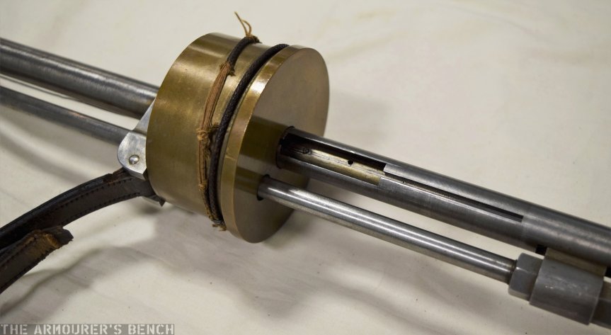
The Curtis rifle’s action appears to lock at the front of the weapon with the bolt handle acting on a hinged, spring-loaded, locking piece or flapper which dropped into place when locked. To unlock the action the bolt handle was sharply pulled to the rear which pushed the locking piece out of engagement and unlocked the action allowing the operating rod to be cycled.
The weapon’s chamber appears to be just forward of the centre of the drum magazine with the striker assembly located behind it. To operate Curtis’ rifle the magazine was loaded and then the user had to unlock the action by pulling the bolt handle backwards. This then allowed the operating rod to be pulled backwards, like a pump action, which pushed the bolt and striker assembly to the rear, cocking the striker, the bolt handle was then returned forward and locked back into position. This chambered a round ready to be fired.
Close up of the Curtis’ brass drum magazine and loading/ejection port (Photo by Matthew Moss, courtesy of the Cody Firearms Museum)
The trigger at the front of the firearm is connected to the striker assembly by a long length of wire. When pulled the wire becomes taught and trips a sear to release the striker, firing the weapon.
Originally Curtis’ patent describes how ‘small punches’ on the bolt face would pierce the cartridge base during firing to enable the spent case to be extracted once the action was cycled. From Winchester’s engineering drawings, however, it appears they replaced this with a more reliable and conventional extractor at the 7 o’clock position of the bolt face.
Given that the weapon would have fired black powder cartridges it is unclear how well the rifle would have faired with sustained firing. The drum magazine would have been susceptible to jamming as a result of powder fouling. This, however, would not have been an issue for Winchester later version of the rifle.
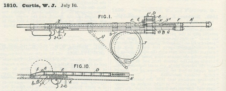
Detail of Fig.1 & Fig.10 from Curtis’ 1866 patent (courtesy of Research Press)
But the Curtis has one more interesting surprise. The original 1866 patent also includes what might be one of the earliest descriptions of a gas operated firearm. One of the most fascinating sections of Curtis’ original patent details how the rifle might have been adapted for gas operation:
“An arrangement is shown in Fig.10, in which the rod G is dispensed with; in this case the barrel may be shorter, not projecting beyond the shoulder; the butt is similar. The breech may be opened automatically by the powder gases, which pass by an opening in the barrel to a cylinder with which works a breech operating plunger.”
Curtis does not go into further detail but he is clearly describing a piston-driven, gas operated system. The patent drawing also depicts an alternative tube magazine instead of the drum magazine.
It is unknown if Curtis ever put his theory to the test and developed his gas system idea further. It is tempting to wonder if, in 1895 when Winchester were assembling their model of the Curtis, if John Browning or William Mason, who were also developing their own gas operated systems at the time, were aware of Curtis’ idea from 30 years earlier. As such Curtis’, admittedly vague, gas system pre-dates the first patents on gas operation by just under 20 years.
If you enjoyed the video and this article please consider supporting our work here.
Specifications:
Action: Slide action
Calibre: .32 Winchester Centre Fire
Feed: ~12 round drum magazine
My thanks to the Cody Firearms Museum at the Buffalo Bill Center of the West for allowing me to examine and film the Curtis. Special thanks to the CFM’s assistant curator Danny Michael for making extra time to open up the case where the rifle Curtis is on display so we could examine it and for also sharing Winchester’s technical drawings and other records.
Thanks also to David Minshall of Research Press.co.uk for his assistance finding Curtis’ original British patent abridgement and to John Walter for digging up some additional information about Curtis’ life.
Bibliography:
‘Winchester Suit Decided’, The Times (Philadelphia), 27th June, 1897
‘Recollections of the Forming of the Pugsley & Winchester Gun Collections: A Talk Given by Mr. Edwin Pugsley at the New Haven Meeting of the AS of AC’, September, 1955.
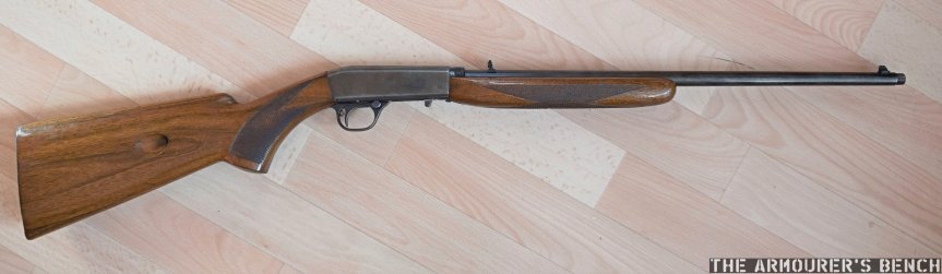
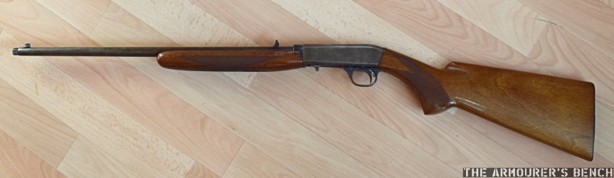
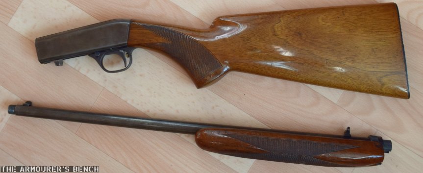
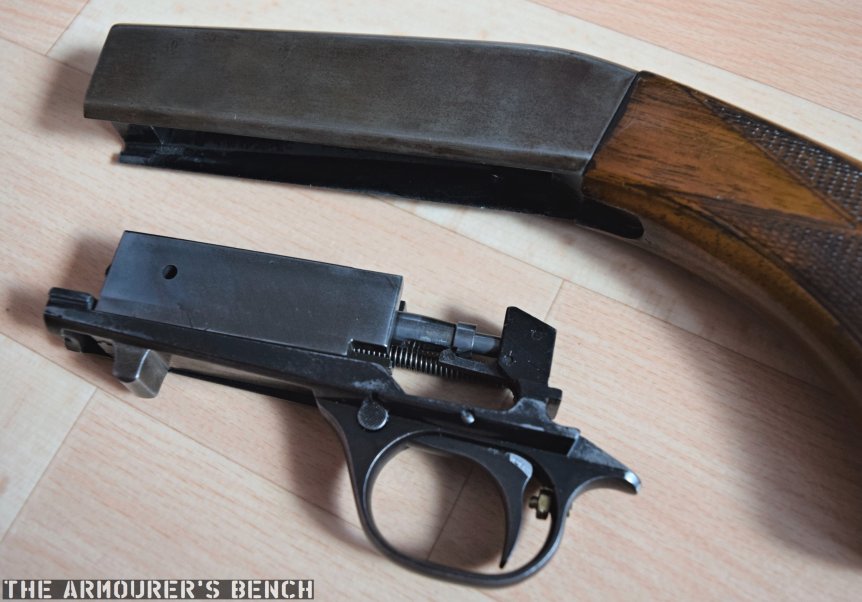
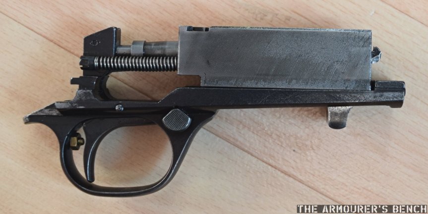
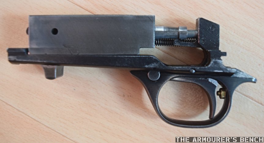
The .22 Semi-Automatic is arguably one of John Browning’s most elegant designs, its balance and handiness is immediately apparent to anyone who has handled or shot one. In our latest video we examined the history behind the design and looked at its features in-depth. You can check out the video and full blog here.
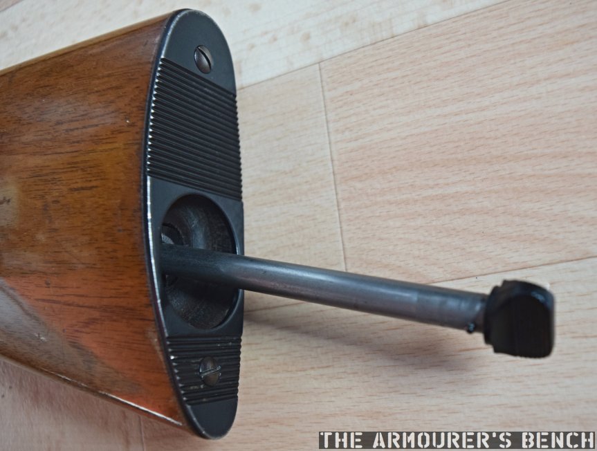
Here are some additional photographs of the rifle:
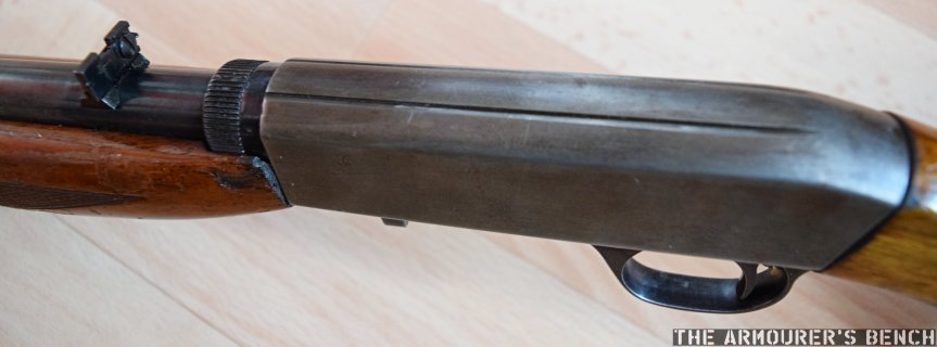
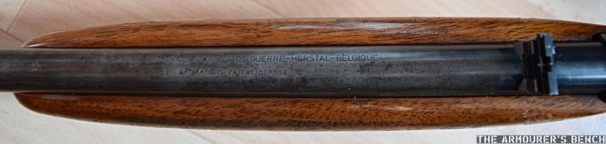
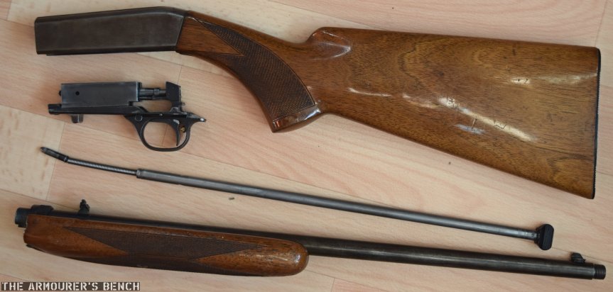
Right side view of the SA .22 (Matthew Moss)Left side view of the SA .22 (Matthew Moss)The .SA .22 is a takedown rifle and splits into two pieces making it more compact for transport (Matthew Moss)Here we can see the rifle’s sight, barrel takedown tension ring and notches cut into the top of the receiver for mounting a scope (Matthew Moss)The rifle’s FN Herstal markings (Matthew Moss)The rifle disassembled with the magazine tube removed and bolt and trigger assembly removed from the receiver (Matthew Moss)The trigger group and bolt slide into the receiver on a pair of internal rails (Matthew Moss)Close up of the right side o the bolt and trigger group (Matthew Moss)Close up of the left side o the bolt and trigger group(Matthew Moss)The butt plate and magazine follower (Matthew Moss)
This weekend I finally had the time to organise all of my photographs and video from my recent research trip to the US. The new 4TB back-up drive I ordered arrived so I could get copies of everything into one place and see what I have. In total it adds up for about 270gb of video and photos! I’m pleased to say tonight I started work on the first video that will come from the trip. I set about editing the photos of the weapon, these will be used in the video and the accompanying blog.
I’m excited to start editing video tomorrow but in the meantime I thought I’d share a few photos with you guys. I’m not going to give the game away and tell you just what this one is – but feel free to throw out some guesses. It’s a very interesting one!
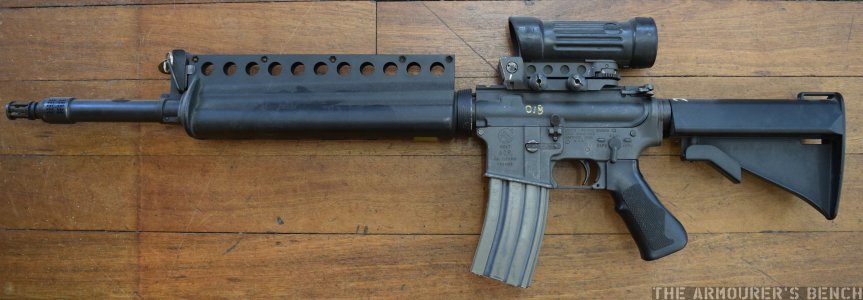
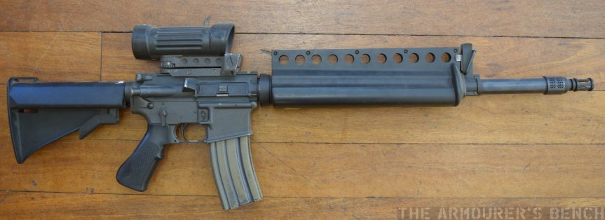
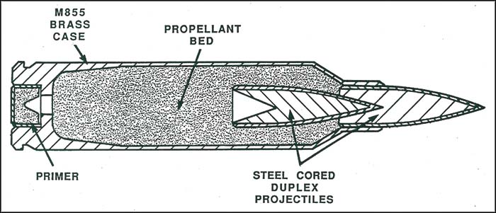
Colt’s entry was perhaps the most conventional of the designs submitted. Based on the rifle the program sought to replace. Colt’s ACR was essentially an improved M16, which fired both conventional 5.56x45mm ammunition as well as a new 5.56mm duplex round. While the duplex round increase hit probability at shorter ranges, it impacted long range accuracy requiring the additional use of conventional M855 rounds.
Left and right side views of the Colt ACR (Matthew Moss)
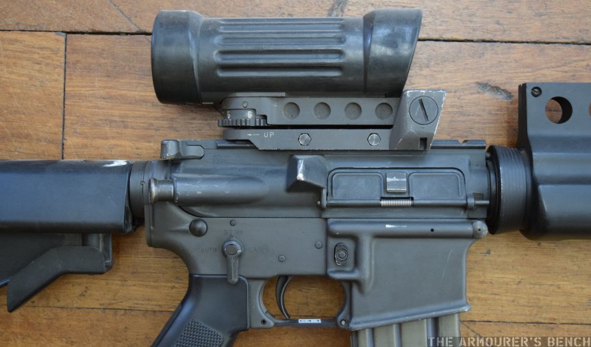
It incorporated a variety of improvements including a new oil/spring hydraulic buffer to mitigate recoil. This resulted in a major decrease in the weapon’s recoil, Colt suggested as much as a 40% mitigation. A reshaped pistol grip and a hand guard which mounted a sighting rib for snap shooting – this stemmed from recommendations from the Human Engineering Lab. The weapon had a flat-top upper receiver which incorporated a weaver rail so a 3.5x optic (an early ECLAN) or a more conventional sight/carrying handle could be fitted.
(Matthew Moss)
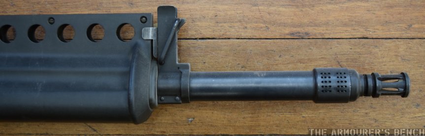
The rifle’s collapsible six position telescopic butt stock was an improved version of that offered with Colt’s carbines. When at full extension the Colt ACR was the longest rifle tested, at 40.6 inch or 103 cm long. A distinctive proprietary muzzle brake compensator (MBC) designed by Knight’s Armament was also added. The Knight’s MBC reduced the rifle’s report by 13.5-decibels and also played an important role in recoil mitigation.
Close up of the Knight’s Armament designed muzzle device (Matthew Moss)Right-side close up of the rifle’s receiver and rail mounted Eclan sight (Matthew Moss)
Colt’s duplex rounds were developed by the Olin Corporation and placed two projectiles nose to tail. The projectiles were copper jacketed steel penetrators. In theory the lead projectile would strike at point of aim while the second would strike somewhere near point of aim with in a theoretically limited area of dispersion. The forward round was 35gr while the second was slightly lighter at 33gr.
Colt’s 5.56mm Duplex round (US Army)
During testing one of the duplex rounds was not properly seated inside the cartridge case and when fired became lodged in the barrel and during the course of fire and the weapon’s barrel blew when another round was fired. This was addressed by a slightly larger propellant charge.
Another negative to the Colt entry was that, in addition to having to carry two types of 5.56mm ammunition, its duplex round offered no improvement in weight and was infact slightly heavier than standard M855 ammunition. While the hydraulic buffer, muzzle device and furniture were not used later, some of the features developed for the ACR entry were later employed in the M16A3 and later A4. These included the selector configuration and the flat-top upper receiver.
If you enjoyed the video and this article please consider supporting our work here.
Specifications (From ACR Program Summary):
Length: 40.6 inches / 103cm (extended) and 36.7 inches / 93.2cm (collapsed)
Weight: 10.3 lbs / 4.67kg
Sights: iron or 3.5x optic
Action: Direct gas impingement
Calibre: 5.56mm duplex round & M855 ball
Feed: 30-round box magazine
You can find out overview article on the ACR program and all of the rifles here
Bibliography:
Advanced Combat Rifle, Program Summary, Vol.1, ARDEC, 1992 (source)
‘Revisiting the SPIW Pt.3’, Small Arms Review, R. Blake Stevens, (source)
The Black Rifle II, C. Bartocci, (2004)
Our thanks to the collection that holds these wonderful examples of the ACR rifles
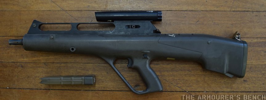
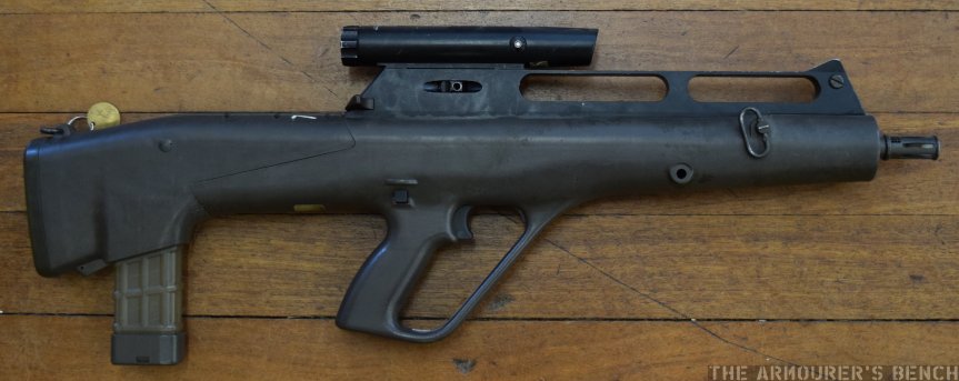
By the mid-1980s Steyr-Mannlicher were already leaders in unconventional small arms designs. In 1977 the Steyr AUG was adopted by the Austrian Army becoming the first generally adopted bullpup service rifle. As such Steyr-Mannlicher’s entry was inevitably a bullpup. Designed by Ulrich Zedrosser the rifle used a gas piston driven rising chamber mechanism which rose and fell to chamber rounds.
Left and right side views of the Steyr ACR, note the small AUG-style (Matthew Moss)
The rifle’s action is described in a 1988 patent (US #4949493) granted to Zedrosser, it explains that ” chamber member, which is separate from the barrel… is reciprocable between a firing position and a loading position in a direction which is transverse to the longitudinal direction of the barrel.” This means that the chamber rises and falls, with the rifle firing from an ‘open bolt’.
The patent goes on to explain the weapon’s action:
When the chamber member is in its loading position its chamber is freely accessible and at one end communicates through a loading opening of the firing block with the interior of a magazine holder and at the other end communicates through an ejection opening of the firing block with an ejection shaft. For the performance of the loading and unloading operation, a slider is provided, which is movable in the longitudinal direction of the barrel and carries a feeder, which is movable from a first end position… when the chamber member is in its loading position, and the movement of the chamber member from its loading position to its firing position is adapted to be initiated before the feeder reaches that end position in which the feeder extends into the loading opening.
One of the other patents (US #4817496) protecting the design explains the weapon’s gas system:
In order to provide a gas drive which is particularly simple and functionally reliable, light in weight and compact, the barrel is provided with a collar or the like, which constitutes a stationary pneumatic piston, and the pneumatic cylinder consists of a sliding sleeve, which surrounds the collar and is longitudinally displaceable between stops.
Patent diagram showing the Steyr ACR’s action (US Patent Office)
The Steyr ACR, like AAI’s entry, fires flechettes but Steyr’s are housed inside a cylindrical polymer case. The bullpup Steyr was the second shortest at 30 inches (76cm) and the lightest of the rifles submitted weighing 8.5 lbs (3.86kg).
The Steyr ACR borrows its ergonomics from its conventional forebearer, the AUG. With a moulded green plastic stock and a similar pistol grip, magazine release, trigger and safety layout. Unlike the AUG, however, the ACR uses an AR-15 style charging handle located at the rear of the sight mounting block and the stock extends further forward to encompass the barrel and gas system. The rifle could be fitted with a variable 1.5x to 3.5x optic or use iron sights.
Comparison of the Steyr ACR with the earlier AUG (Matthew Moss)
As discussed earlier the rifle does not use a conventional bolt, instead it uses a rising chamber, as a result the rifle fired from an open bolt. A live round only entered the chamber after the trigger had been pulled, thus reducing the potential for cook-offs. Spent polymer cases were pushed out of the chamber and ejected from an opening just in front of the magazine well.
Steyr’s Polymer Cased Flechette round (US Army)
Feeding from a 24-round box magazine, made from the same translucent material used in conventional AUG magazines. The magazine goes from double stack to single stack, to allow it to feed reliably, as a result the capacity had to be shortened. A high capacity drum magazine was planned but not provided for the trials. The polymer case held a fin stabilised 9.85 gr flechette with a moulded four piece sabot which broke up soon after exiting the muzzle. This was identified as a shortcoming as it risked hitting nearby troops.
ACR Program Summary recognised the Steyr ACR entry as “the simplest weapon, the simplest round, and the most cost effective approach of any of the ACR contenders.” The report noted that the weapon’s “greatest current deficiency is its poor round to round dispersion characteristics.” This was a criticism levelled at both the flechette firing entries, it essentially ended the US Army’s interest in flechette firing individual weapons, relegating the concept to larger area effect weapon systems.
If you enjoyed the video and this article please consider supporting our work here.
In our latest video we take a look at the massive 15 Inch Coastal Guns that protect the port of Mahon in Menorca. The guns, built by the British Vickers company, could fire an 860kg shell up to 35km.
The battery of two 15 or 381mm guns was added to the Fortalesa Isabel II’s emplacements in the early 1930s and were in active service for nearly 80 years. For more information on their history and design, check out the video and full in-depth blog here.
Below are some photographs I took of the battery and its ancillary support buildings. While researching I also found a couple of great contemporary photos.
A view of the 15 Inch Vickers Gun from the rear (Matthew Moss)A view of the front of the gun turret’s housing, while not thick enough to withstand a direct hit the turret would protect against shrapnel (Matthew Moss)A view of the front of the gun, note the small hatch in the front of the gun housing, this would have been the gun aimer’s postion (Matthew Moss)The sliding hatch and crane used to bring up cordite charges when the gun was in action. (Matthew Moss)A view of the rear of one of four supporting 6 Inch Vickers guns (Matthew Moss)The battery’s support buildings: Stores, offices, barrack blocks(Matthew Moss)The Battery’s other 15 Inch Gun on the other side of the old quarry that houses the battery’s support buildings (Matthew MossThe left side of the turret, not the ladder for roof access (Matthew Moss)
A facebook group for those who served at Fortales Isabel II has a number of brilliant contemporary photographs of the guns:
These photographs show the guns being transported by a specially laid, segmented rail track in the early 1932s, the first shows the guns at the dockside with another showing it being moved through a busy street.
The group also has some contemporary photographs of the gun emplacements including the rangefinder and the inside of the gun housing:
The gun aimer’s position with communications to the rangefinder bunkers near by:
The group also has some excellent recent photos of the restored interior of the gun turret the magazine below. The first photos show the magazine and system for bringing the 860kg shells up from the projectile store:
Sign reads: ‘Ordinary projectiles will only be used with reduced load‘
Great shot of the various tracks, winches and lifts used to get the massive shells up to the turret:
Interior shot of the turret with a shell ready to be winched onto the loading tray and loaded into the breech:
View of the gun aimer’s positions complete with shining brass speaking tubes and controls:
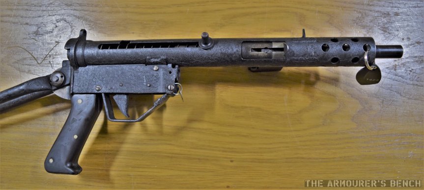
During our first research trip last spring I had the opportunity to examine an unusual ‘hybrid’ Sten submachine gun. The weapon combined a MkII Sten’s receiver with a MkIII’s magazine housing. Added to this was a proprietary folding stock and a new fire control group and pistol grip.
Very little is known about the hybrid Sten with Peter Laidler’s book The Sten Machine Carbine mentioning it and the later Osprey book by Leroy Thompson sharing a photograph and brief caption which calls it an “experimental version of the Mk III.” It is also unclear exactly when it was built.
Below are some photographs I took of the Sten, lets look at some of the interesting features of the Hybrid Sten.
left side of the Sten with the stock folded flush under the receiver (Matthew Moss)
No production Variant of the Sten was fitted with an under-folding stock, the Australian Austen, however, directly copied the MP38/40. The entire weapon is covered by a layer of textured, crackle paint finish, this was commonly used on commercial Sterling Mk4 submachine guns. The weapon has a short, 3.5 inch, perforated fore-end welded onto the front of the tube receiver that appears to be from a Lanchester.
Rear right of the weapon close up of its pistol grip, stock and trigger housing (Matthew Moss)
The under folding stock is rudimentary but effective, the butt plate swivels free but the lock up is quite secure. It uses the receiver main spring-loaded return-spring cap. The folding stock attaches to the pistol grip assembly (which can be seen detached below).
The proprietary rectangular trigger group housing brazed onto the tub receiver is unlike any other Sten and lacks a fire-selector.
Left side of the Sten with its pistol grip and stock assembly detached (Matthew Moss)
The pistol grip itself is made from paxoline, a form of early resin plastic. The shape shape of the pistol grip does not resemble any production or prototype Sten grip. A simple hand-stop, made from a bent piece of sheet metal, has also been added in front of the weapon’s ejection port to prevent the user’s hand moving back and fingers being caught if gripped by the forend.
Right side of the Sten with its stock unfolded (Matthew Moss)
While the origins of the hybrid Sten remain unclear I don’t believe it was an officially made prototype. While impressive it is relatively crudely assembled and does not match the Sten prototypes made by Enfield, such as the VI. Intriguingly, the magazine housing of the weapon has been stamped ‘PILOT’ below the usual ‘STEN MkIII’ stamp. I suspect that the weapon may have been put together by a unit armourer, perhaps authorised by a superior officer to suggest improvements or as an unofficial project gun.
UPDATE: Their is some evidence emerging that this Hybrid Sten may be related to the T42 Sten prototype, part of the Sten MkIV development program. Where this hybrid fits into the story is not yet clear but the similarities are striking, when we have more information we will revisit this weapon.
If you enjoyed the video and this article please consider supporting our work here.
In the first part of Vic’s special episode on the AR-10 we brought you a remastered version of the fascinating 1958 ArmaLite/Fairchild promotional sales film made for ArmaLite salesmen, like Sam Cummings and Jacques Michault, to show to prospective buyers of the new rifle. Back in the 1990s Vic was lucky enough to scan Michault’s copy the film and has recently remastered with better image quality.
Below you can find the video, time stamped to begin at the promotional film (although I highly recommend you watch the entire video for Vic’s introduction to the early history of the AR-10).
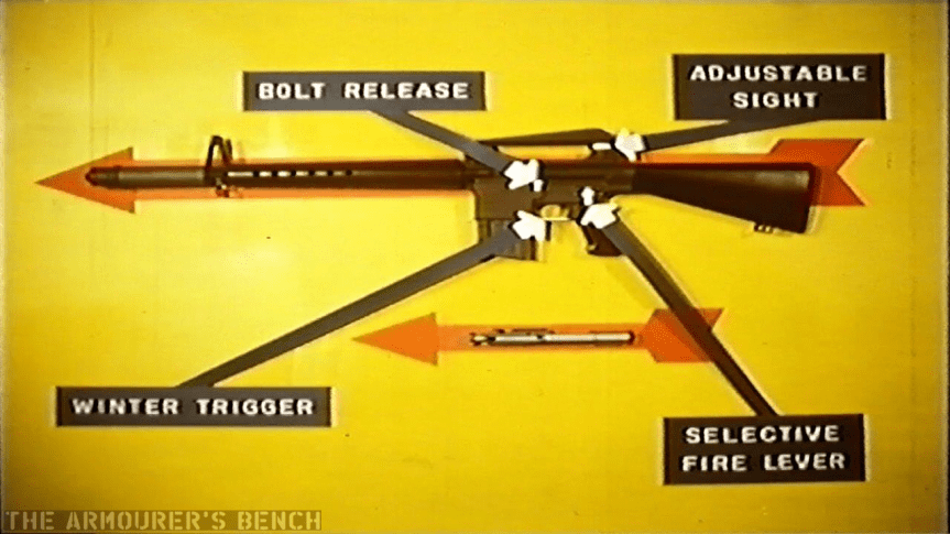
Lets break the video down, with the help of some screen captures. The film opens with a rifleman emerging from the sea, firing as he advances. The film then explains Fairchild’s background and beings to explain the features of the rifle.
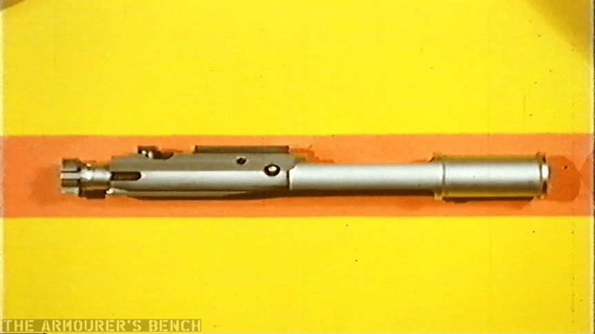
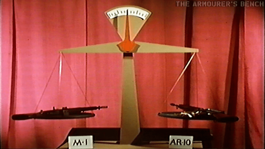
Arrows point out some of the AR-10s controlsA close up of the rifle’s bolt and carrierA set of scales is used to demonstrate how the AR-10 (plus 50 rounds) is equal to an M1 Garand
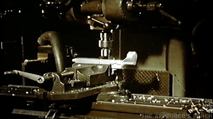
The film then shows several shots of the rifle’s lower receiver being milled.
The milling of the rifle’s aluminium-alloy forged receiver
None other than the rifle’s designer himself, Eugene Stoner, then takes an AR-10 from a wall display and proceeds to completely disassemble it.
Stoner standing in front of a display board holding three AR-10 prototypes and AR-5s and an AR-7 survival rifle
Stoner completely strips the rifle, its muzzle device and its magazine before Charles Dorchester, ArmaLite’s production manager, demonstrating the rifle’s operation and subjects it to sub-zero temperatures and once again firing the rifle.
Chuck Dorchester submerges he rifle in what appears to be liquid nitrogen
Dorchester again test fires the rifle
The film then shows the rifle being used in a variety of roles:
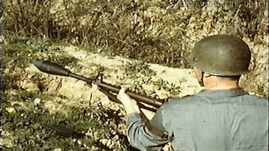
AR-10 being fired with a scope mounted to the carrying handleThe AR-10 being fired from a bi-pod in the light support role, feeding from 20-round magazines, the AR-10 LMG could easily be switched between magazine and belt feeding by removing the belt feed assemblyAn ENERGA rifle grenade being fired from the AR-10, the US Army had adopted the ENERGA as the M28 rifle grenade in 1950.
Stoner then covers the rifle with sand before running five magazines through the rifle in quick succession to demonstrate reliability:
This slideshow requires JavaScript.
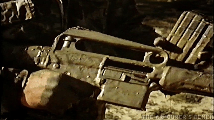
The rifle is then submerged in mud (with its dust cover closed) and demonstrated again.
AR-10 covered in mud
The film then shows how simple field stripping and cleaning is before Stoner demonstrates the belt-fed variant of the rifle:
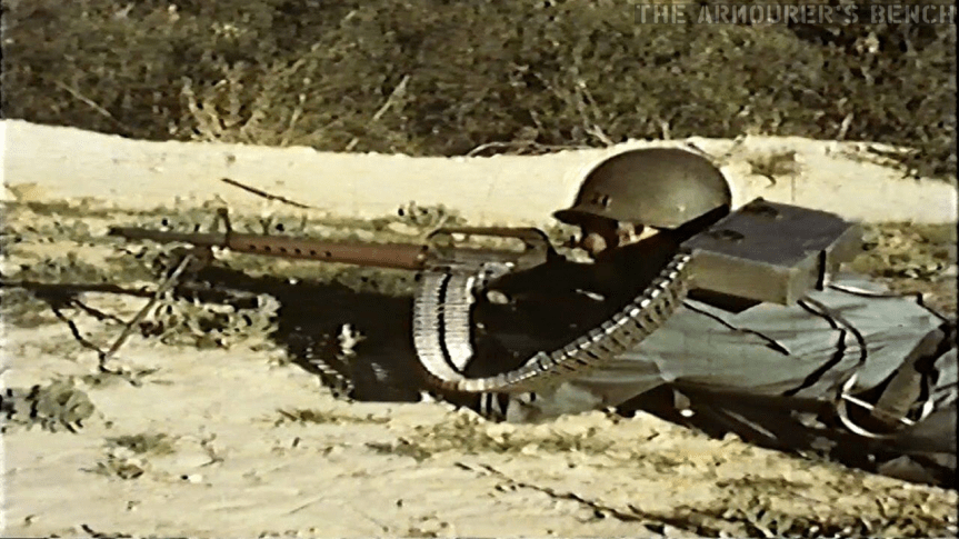
A rifleman demonstrates the AR-10 in its belt-fed configuration, changing position several times before switching to feeding from magazines. Note also the ‘backpack’ belt box and controlled chute/feedwayStoner firing the belt-fed AR-10Stoner with a happy grin on his face before opening up with the AR-10,Note the bolt link port in the lower receiver
Don’t forget to check out the full episode and the accompanying blog here!
If you enjoyed the video and this article please consider supporting our work here.


 Left and right side views of the Colt ACR (Matthew Moss)
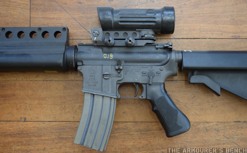
 Left and right side views of the Steyr ACR, note the small AUG-style (Matthew Moss)
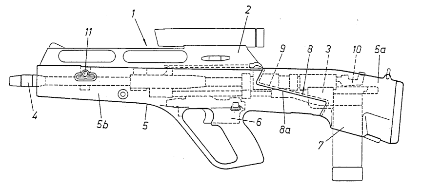


.Movie_Snapshot")
.Movie_Snapshot")
.Movie_Snapshot")
.Movie_Snapshot")
.Movie_Snapshot")