By early 1945 Nazi Germany’s situation was desperate, with no real hope of victory left desperate holding actions became the order of the day. In order to try and stem the advance of the Red Army in the East and the Allies in the West (and south), the German government raised a new militia, the Volkssturm (or in English: ‘people’s storm’). This optimistically named force made up of all men aged between 13 and 70, they were expected to defend their local areas, much like the British Home Guard formed in 1940.
In order to arm the Volkssturm and the remnants of the rest of Germany’s armed forces, stores of older weapons, such as Gewehr 98s and 88s and MG08s were re-issued and a broad variety of captured foreign weapons.
Even so there was still not enough weapons to equip the newly improvised ‘volunteer’ force. As such, in Autumn 1944, German industry was directed to create prototypes of simpler, cheaper weapons that might be mass produced quickly with minimal tooling. This project was dubbed the Volksgewehr-Programm, which evolved from the earlier Primitiv-Waffen-Programm which began in 1943 and saw the development of the EMP44. . These primitive weapons had to be made quickly with the materials at hand. The Volksgewehr-Programm spawned a number of prototypes with varying degrees of sophistication, the so-called VolksGewehr or ‘people’s guns’.
The best known these ‘people’s guns’ is perhaps the Gustloff Volkssturmgewehr – often referred to as the VG 1-5. Such was the chaos and rapid development of the weapon we’re examining today it was known by a plethora of names in various wartime documents, including: Selbstladegewehr [self-loading rifle], Selbstladekarabiner [self-loading carbine] and Volks-Selbstladekarabiner 45 [self-loading carbine 45]. As W. Darrin Weaver points out in his book ‘Desperate Measures‘ these carbines were never officially referred to as the VG 1-5. Weaver’s suggests instead that the proper name would the ‘Volkssturmgewehr‘ while Wolfgang Peter-Michel suggested in his 2017 book ‘Volksgewehre: Die Langwaffen des Deutschen Volkssturms‘ that ‘Volksmaschinenpistole’ was the term officially used.
The Gustloff Volkssturmgewehr was undeniably the most complicated of the Volksgewehr-Programm guns. A semi-automatic, gas delayed blowback operated carbine chambered in Germany’s new intermediate 7.92x33mm Kurz cartridge. Developed by Karl Barnitzke, Gustloff Werke’s chief designer, initial versions of the weapon were select-fire and designated the MP 507. Gustloff submitted a semi-automatic variant of the carbine to the Volksgewehr-Programm trials but was rejected in November 1944, ostensibly due to cost, comparative complexity and ammunition consumption.
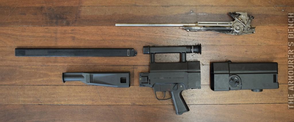
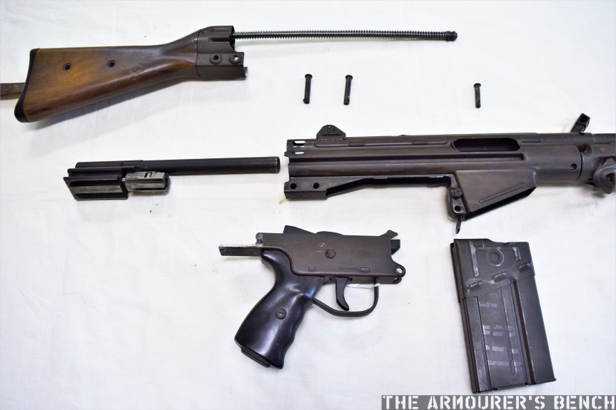
Field stripping the Gustloff Volkssturmgewehr:
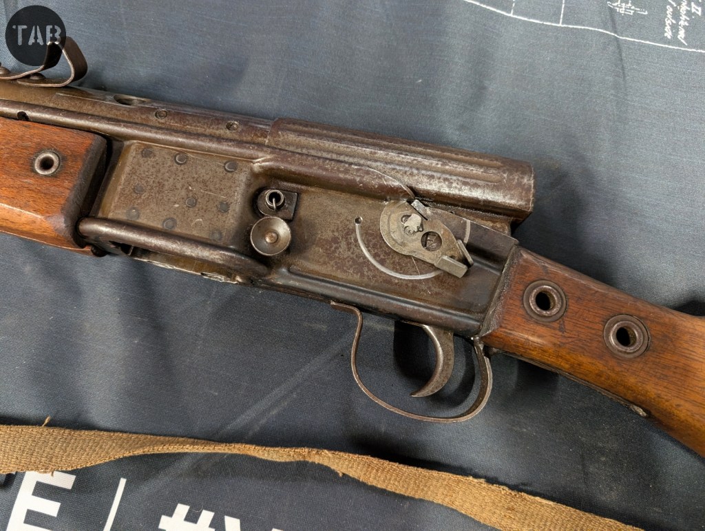
First check the weapon is in a safe condition. Then unscrew the knurled nose cap by lifting the retaining flat spring. Then slide out the weapon’s mainspring. Remove the single retaining pin [which does not fit into any of the slots in the stock, despite looking like it will]. Remove the safety catch, this is retained by a raised flat that sits under one of the stamped receiver’s folds. Lift trigger assembly up, out of the rear of the receiver, then slide the bolt and barrel shroud assembly forward and off the barrel.
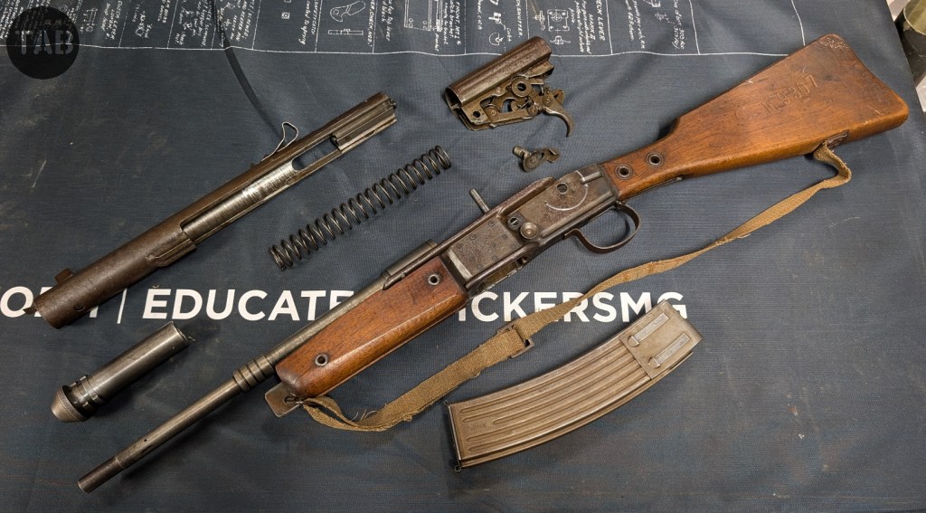
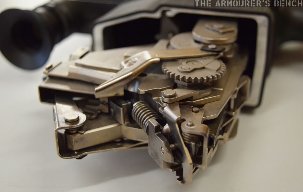
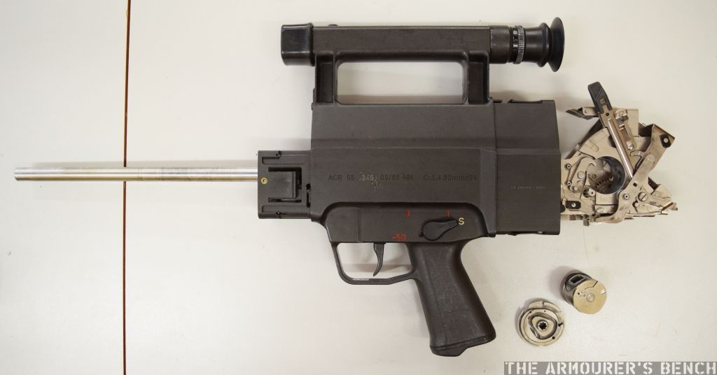
Looking over the disassembled weapon we can see the two coarse interupted threads which retain the nose cap. We can see one of the four gas ports and gas expansion chamber rings. The trigger and firing mechanism are one complete assembly. the breach block is pinned into the barrel shroud (which also acts as the body of the gas expansion chamber). Note the rough welds on the lower guide piece. Not the extremely rudimentary charging handle and front and rear sights.
How It Works:
The Volkssturmgewehr‘s design uses a gas-delayed blowback action. On firing, once the projectile leaves the muzzle, the propellant gases expand and push the spent case and the unlocked breech rearwards, the case is ejected and the barrel shroud/gas cylinder/bolt assembly recoils. As the weapon fires and the projectile passes through the barrel the weapon vents gas from the barrel through four small holes, the gas expands into the cylinder/chamber, which is formed around the barrel by the shroud, this is intended to slow the rearward movement of the bolt assembly. The mass of the barrel shroud/gas chamber/bolt assembly also aids in slowing the opening of the breech.
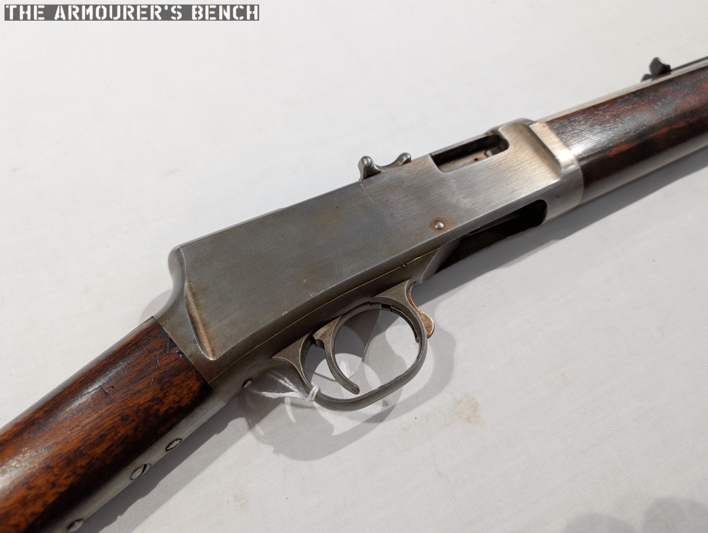
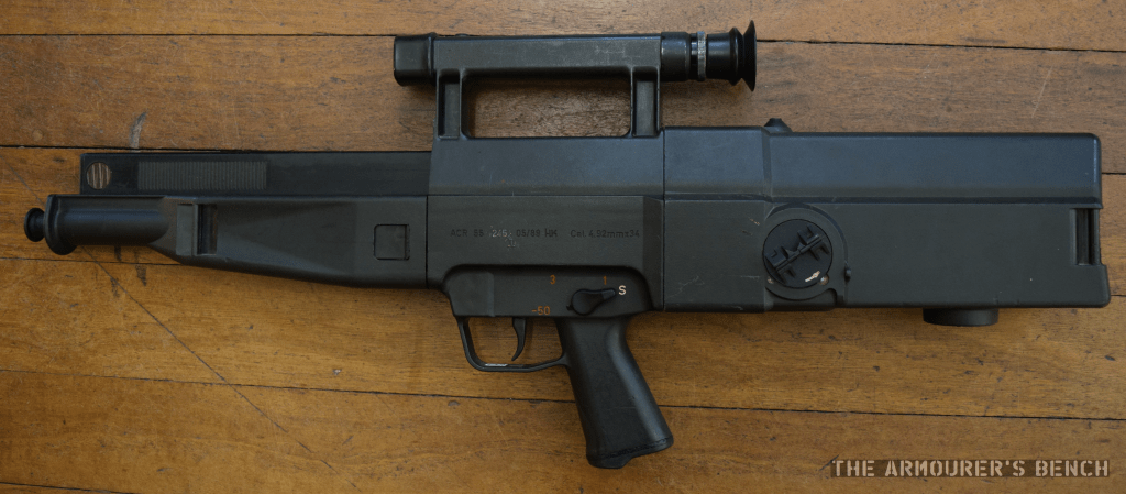
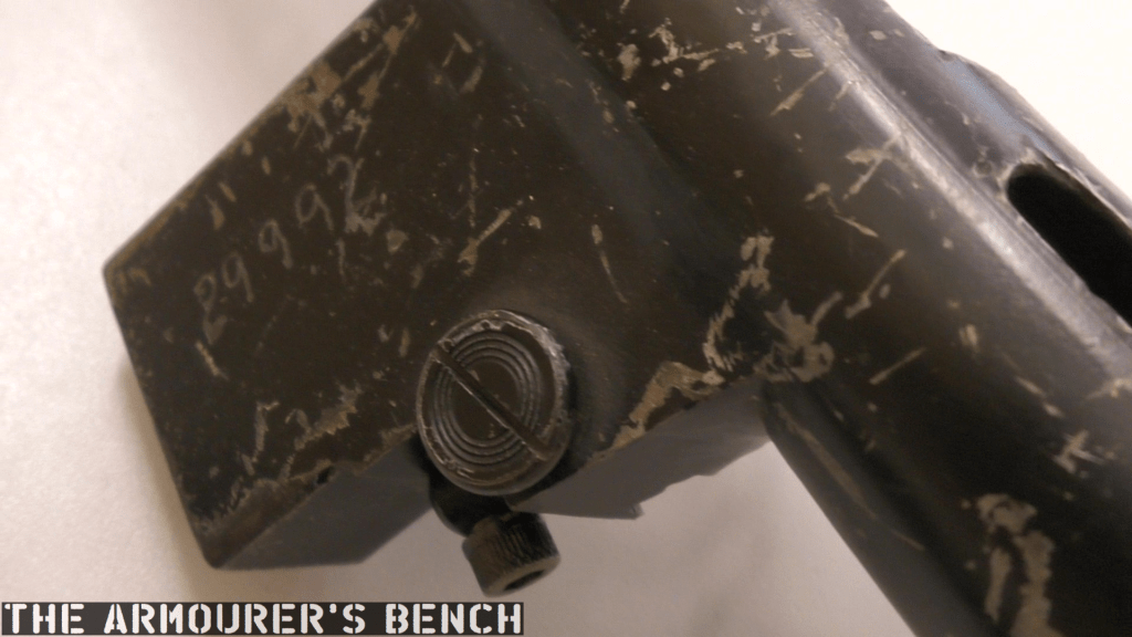
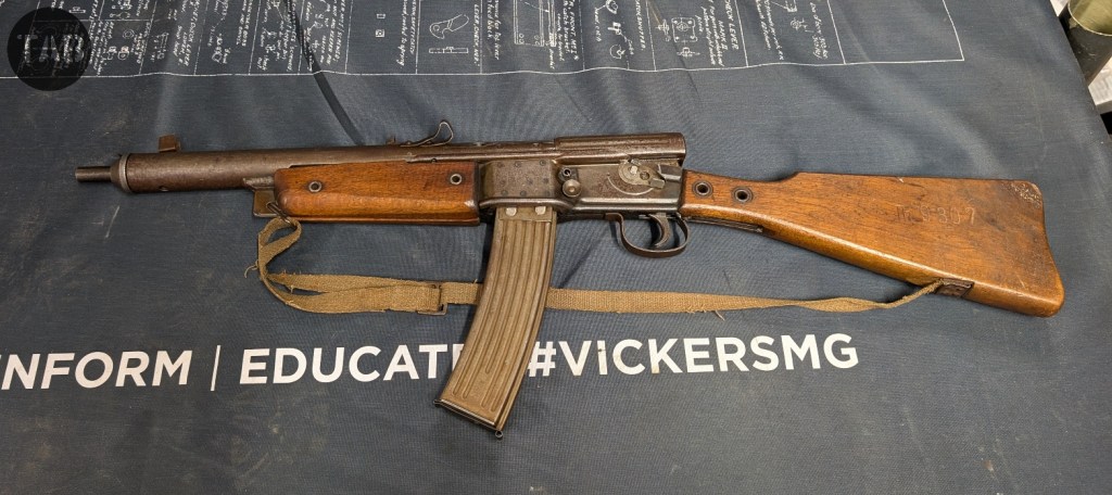
As the situation continued to deteriorate, Gauleiters (or regional leaders) were given carte blanche to direct local weapon production and procurement and the Gustloff Volkssturmgewehr was resurrected and put into production Thuringia’s Gauleiter Fritz Sauckel. As such the weapons do not have the typical Waffenamt acceptance markings. The first guns were completed in late 1944, with the production line ramping in January 1945. This particular example, with the serial Th. 9307 stamped into the stock, was assembled near the end of production.
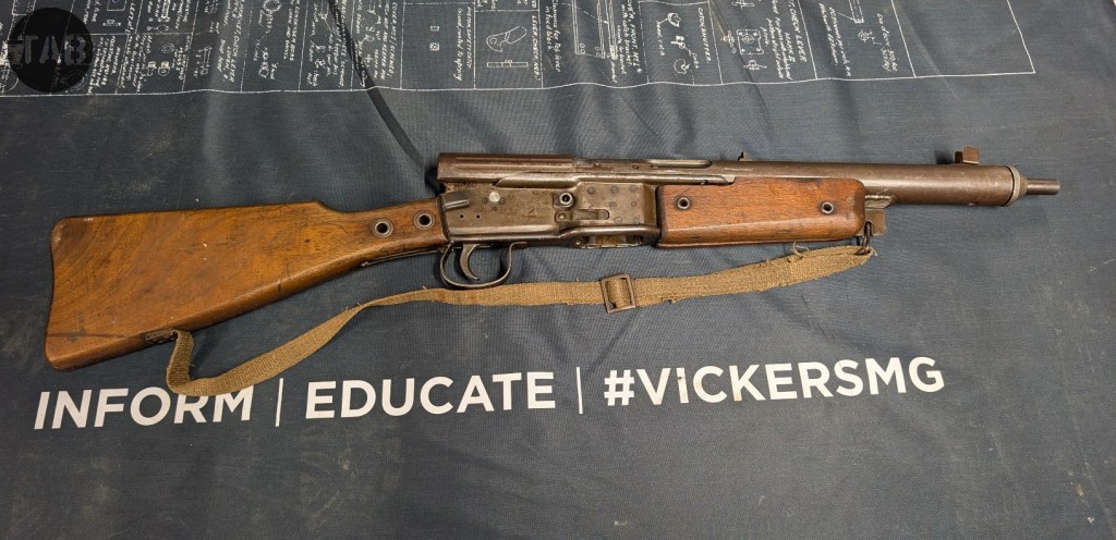
Barnitzke claimed that the weapons took only 3 hours to manufacture and that approximately 10,000 were built. The Volkssturmgewehr has fewer than 40 metal components and is built around a two piece riveted stamped receiver. It has a roughly machined barrel, a stamped receiver cover and simple wooden furniture. The characteristic sling often seen with the were permanently attached to the weapons furniture and are believed to be derived from a gas mask canister straps with extra reinforcement.
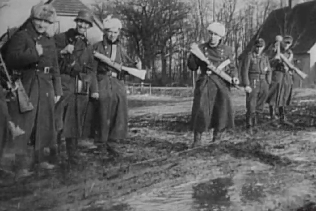
Unlike the other Volkssturm weapons there is contemporary imagery in the form of photos and newsreel footage which show that Volkssturmgewehr reached the front and was used. It is believed that the weapons predominantly saw use with Volksturm units on the Oder Front, to the east of Berlin.
As the war ended the US Army captured a number of examples of the weapon and one was sent to the US Army’s Aberdeen Proving Ground for evaluations in July 1945. The report, which is likely the first document to refer to the weapon as the VG 1-5, found the Volkssturmgewehr ‘crudely made’ concluding that “accuracy was poor, general functioning was fair with the exception of recurrent feed failures… in general, the weapon appeared capable of fulfilling the mission for which it was designed” [Report No. 06-64-TM-OC, July 1945]
Special thanks to the Vickers Machine Gun Collection for allowing me to film this item from their incredible collection, I can’t encourage you enough to check out their videos, website and amazing collection.
Bibliography:
Desperate Measures : The last-Ditch Weapons of the Nazi Volkssturm, W.D. Weaver (2005)
Deutsche Sturmgewehre bis 1945, P. Senich (1998)
Volksgewehre: Die Langwaffen des Deutschen Volkssturms, W. Peter-Michel (2017)
German Submachine guns & Assault Rifles of World War II, Aberdeen Proving Grounds Series (1968)
Support Us: If you enjoyed this video and article please consider supporting our work here. We have some great perks available for Patreon Supporters – including early access to custom stickers and early access to videos! Thank you for your support!