Hands On with the New Colt Canada C25

In March the Canadian Armed Forces selected a new rifle to replace their venerable C7 and C8 rifles. The Canadian Modular Assault Rifle (CMAR) program has seen Canada make an initial order for 30,000 General Service (GS) variants of the new rifle. In selecting the CMAR the Canadian Armed Forces have wrestled with the fundamental question facing many major armies around the world as they come to replace their current generation of small arms – how do you defeat enemies with level IV body armor?

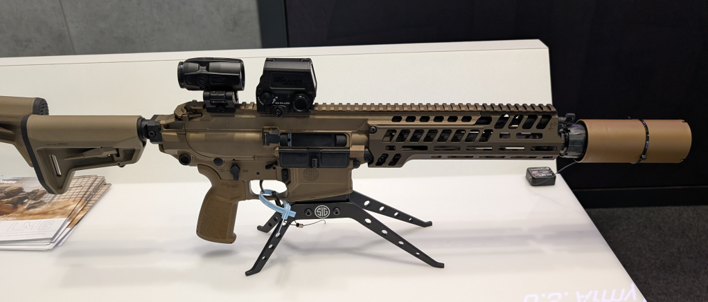
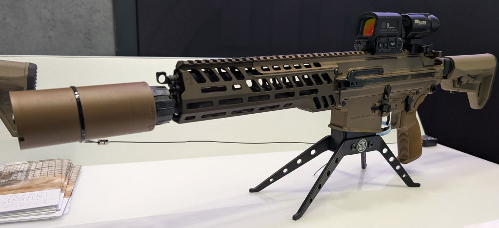
New Colt Canada C25 at the range in Copenhagen (Matthew Moss)

The US Army has opted for power and penetration with the Next Generation Squad Weapons program and the new 6.8x51mm round but not every military sees a larger, more powerful round as the answer. While the US Army has gone all-in on the 6.8mm family of ammunition for its close combat units, other nations – for various reasons – will be more cautious, not wanting to move away from the proven 5.56x45mm and 7.62x51mm standardised ammunition natures. After assessing a number of approaches the Canadian Armed Forces and Defence Research and Development Canada (DRDC) have chosen to stick with 5.56x45mm for their soldiers’ individual weapons. The C25 Canadian Modular Assault Rifle developed by Colt Canada in conjunction with the Canadian Armed Forces aims to improve the average Canadian soldiers’ capability to defeat enemies with modern body armor by giving them a modern, modular rifle which improves their practical accuracy.
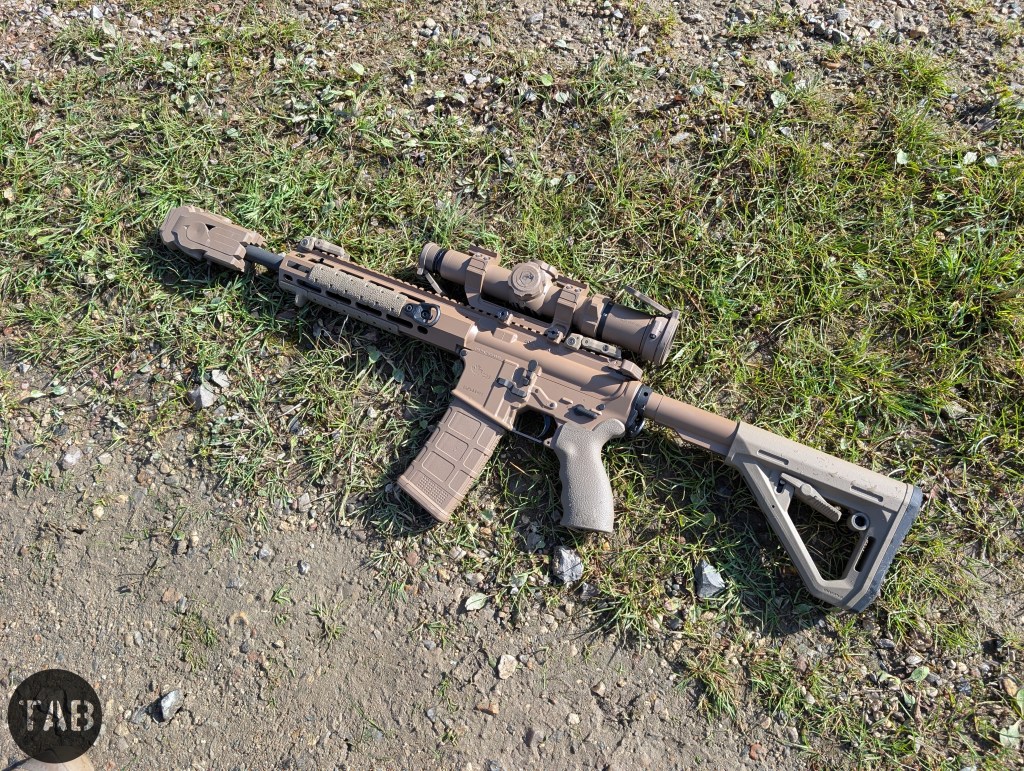
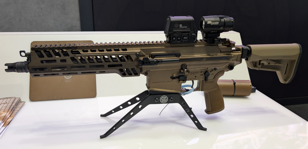
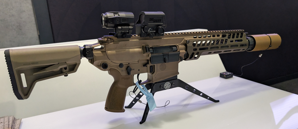
Left-side profile of the C25 (Matthew Moss)

Canada’s New Doctrine

With the new C25 rifle Canada aims to enable close combatants to strike unprotected or more vulnerable areas of their opponents’ bodies. Conventionally, troops are taught to aim for centre mass, a significant area that contains many vital organs. With the proliferation of modern body armour, which protects this area and reduces the effectiveness of 5.56mm ammunition, Canada believes targeting less well protected areas such as: the head, neck, lower abdomen, groin and legs is the modern soldier’s best option. To reliably hit these areas, which are harder to hit than centre mass, soldiers will need to be more precise with their shot placement – Colt Canada say the C25’s configuration has been developed with this in mind. However, for this new doctrine to be truly effective Canadian troops will probably need more time at the range.
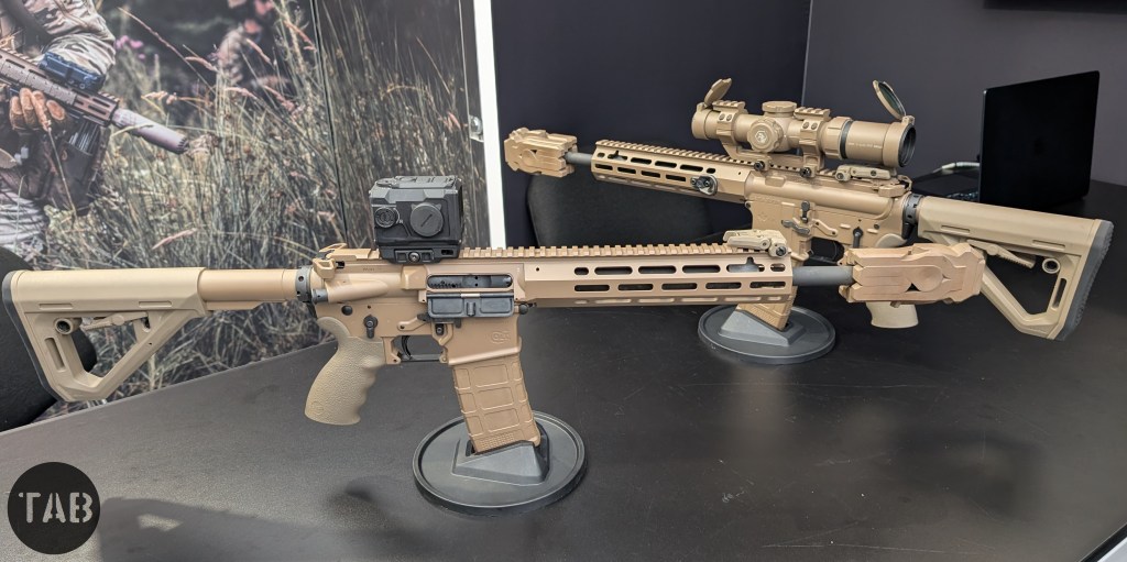
C25 with Colt Optics’ CQS-1 red dot and 1–6x Low Power Variable Optic (Matthew Moss)

How Does the C25 Improve Soldier Accuracy?

The C25 is an evolution of the Colt Canada C8A4 (known as the Modular Rail Rifle) so at its core the C25 uses the classic direct impingement system, or expansion gas bleed-off as Colt Canada describe it. The rifle’s length ranges between 32in (813mm) and 35.2in (895mm), depending on stock position, and weighs in at 7.61lbs (3.45 kg) unloaded and without optics and accessories, but with an MFMD mounted.

Increasing hit probability and the impact of rounds on target was the key consideration for Colt Canada when working with the Canadian Armed Forces. The C25 achieves this in a few ways: improvements to the rifle’s ergonomics (new MLOK handguard, a monolithic upper receiver and fully ambidextrous controls), a new two-stage trigger, a new 1-6X low power variable optic (LPVO) and a new muzzle device – the Millbrook Strategic Sciences MFMD or Multi-Function Muzzle Device. These features combine to improve the soldiers’ practical combat accuracy.

How do these features help improve practical accuracy?

The monolithic upper receiver provides improved rigidity and stability for the mounting of optics and enablers. The two-stage trigger provides more control under stress and greater precision, the new LPVO allows the user to aim more precisely at various ranges and the MFMD helps reduce perceived recoil with a smoother impulse as well as reducing flash and blast at the muzzle.
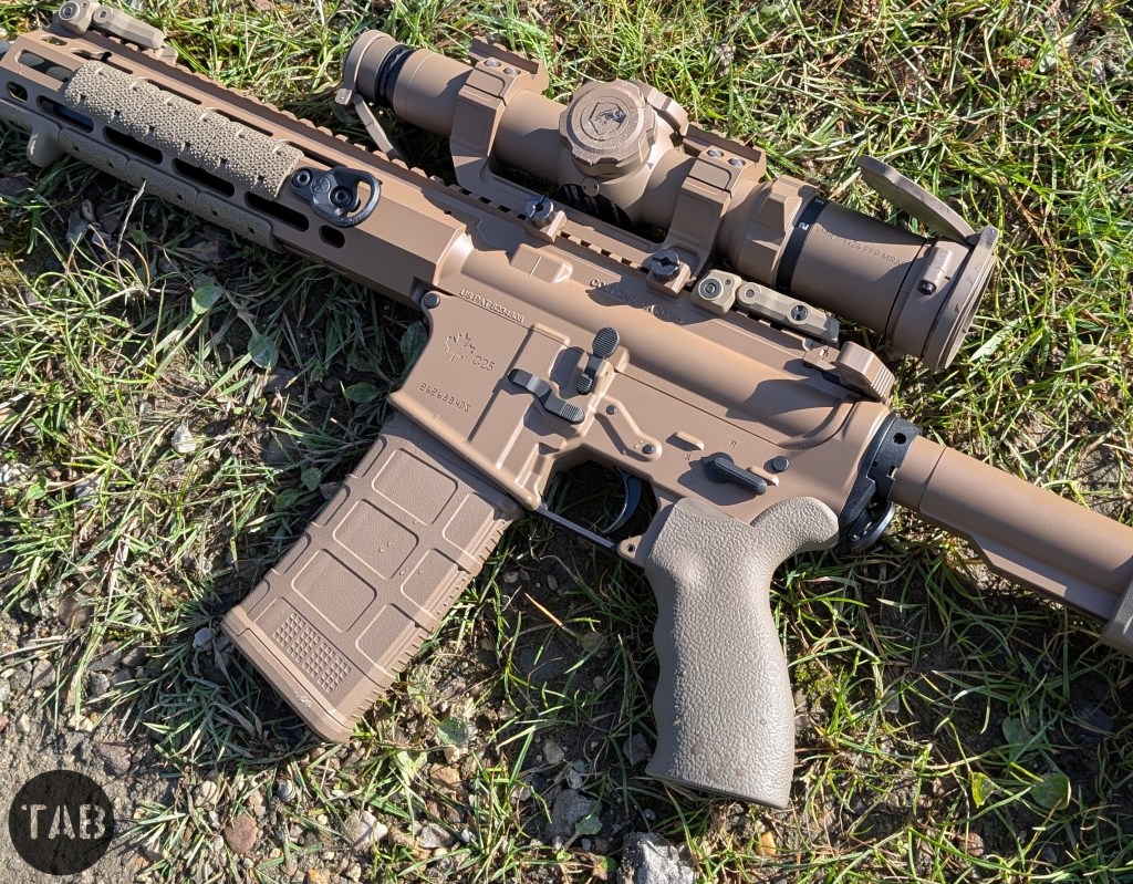
C25 with 1–6x LPVO at the range (Matthew Moss)

At the Range with the C25

In Copenhagen, I had the opportunity to get behind the C25 for the first time. Putting around 100 rounds of Sellier & Bellot SS109 through a C25 with Colt Optics’ 1-6x Low Power Variable Optic.

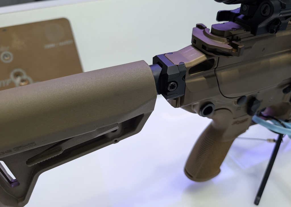
In terms of points of contact with the weapon, the 5-slot MLOK forend, mounting to the monolithic upper receiver, minimises flex and offers plenty of room for mounting enablers like lights and lasers. The C25 has the very ergonomic ERGO 2 pistol grip and Magpul DT carbine buttstock as standard and a full suite of ambidextrous controls.
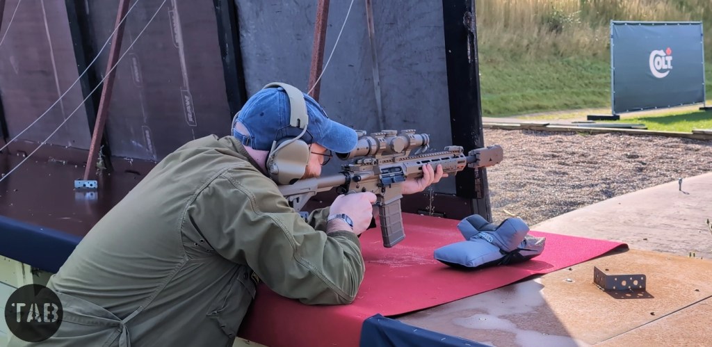
C25 has a 2-stage trigger (Matthew Moss)

The C25 also benefits from a new two-stage trigger which Colt Canada says is intended to ensure a more sensitive, clearly perceptible and predictable trigger pull with each shot. The trigger had smooth first stage take-up, with the second stage breaking predictably, followed by a short reset. The rifles have a 13.7in (348 mm), 1:7 twist, cold hammer-forged chrome-moly vanadium steel barrel with improved geometry to reduce disturbance during the travel of the projectile. The C25 is optimised for Canada’s current SS109 (C77 Ball) but Colt Canada are exploring other 5.56x45mm loadings.

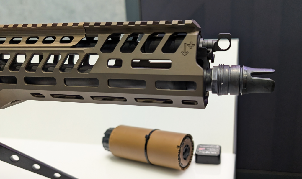
Colt Canada noted that C25 has been optimised to be effective out to 300m, though with the Colt Optics’ 1-6x LPVO I can see a skilled rifleman easily reaching out further. The barrel is tipped with a directly threaded MFMD, which will be standard across the whole C25 fleet – making Canada the first country to equip its all of its service rifles with a suppressor as standard. There has been a lot of hype around the MFMD so I was excited to give one a try.

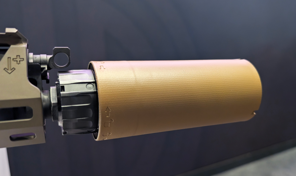
The MFMD’s flow-through design is driven by fluid dynamics which leads to its very unconventional profile. Colt Canada noted that they had tested the MFMD, which is 3D printed from inconel, extensively putting 10,000 rounds through it. Canada reportedly trialled 14 suppressors from various manufacturers before selecting the MFMD.
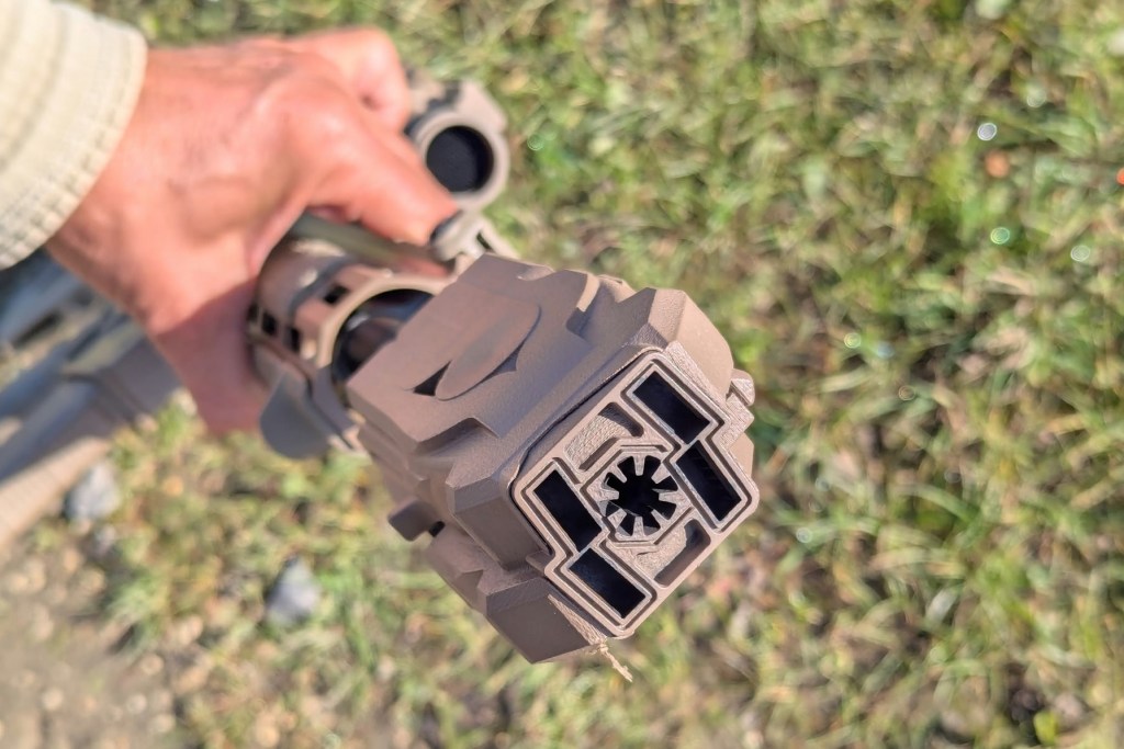
A muzzle-view of the MFMD (Amael Kotlarski)

As a left-handed shooter I found the MFMD’s flow-through design minimised gas pushed out the rear of the upper receiver and into my face and I was impressed by the MFMD’s sound signature mitigation. The base module of the MFMD is designed to work as an all-in-one flash hider, muzzle brake and suppressor. It can be augmented with an additional module, the SD, which offers further suppression but the Canadian Armed Forces have opted for just the base MFMD. Despite this the base muzzle device still suppresses the C25 to around 140dB, this was certainly noticeable on the firing line.

The new carbine comes in the increasingly ubiquitous flat dark earth finish, marking the end of the unique green furniture (pistol grip, stock and hand guards) of the C7 and C8 family of Canadian weapons. I’m a fan of the classic Canadian furniture colours, optimised for the plains and woodland, so I’m sad to see it replaced by FDE. Sadly, the new muzzle device also means no bayonet mounting.
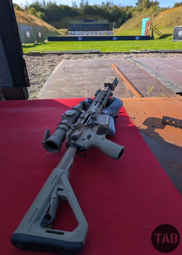
The C25 has a Magpul DT carbine buttstock, Colt Optics LPVO and an MFMD (Matthew Moss)

All in all, the C25 left the impression of a capable weapon: robust, accurate and ergonomic. While we didn’t shoot groups on paper engaging plates and a crossing target at 100m supported and unsupported was pretty easy. The new MFMD has a practical effect, and the rifle as a package seems well placed to fulfil Canada’s pragmatic new doctrine.

As the UK’s Project Grayburn begins to ramp up rifles like the C25 are going to be key competitors in the upcoming UK rifle programme.


Special thanks to my friend and colleague Amael Kotlarski for filming some of the range footage used in this article’s video.


Support Us: If you enjoyed this video and article, please consider supporting our work here. We have some great perks available for Patreon Supporters – including early access to custom stickers and early access to videos! Thank you for your support!
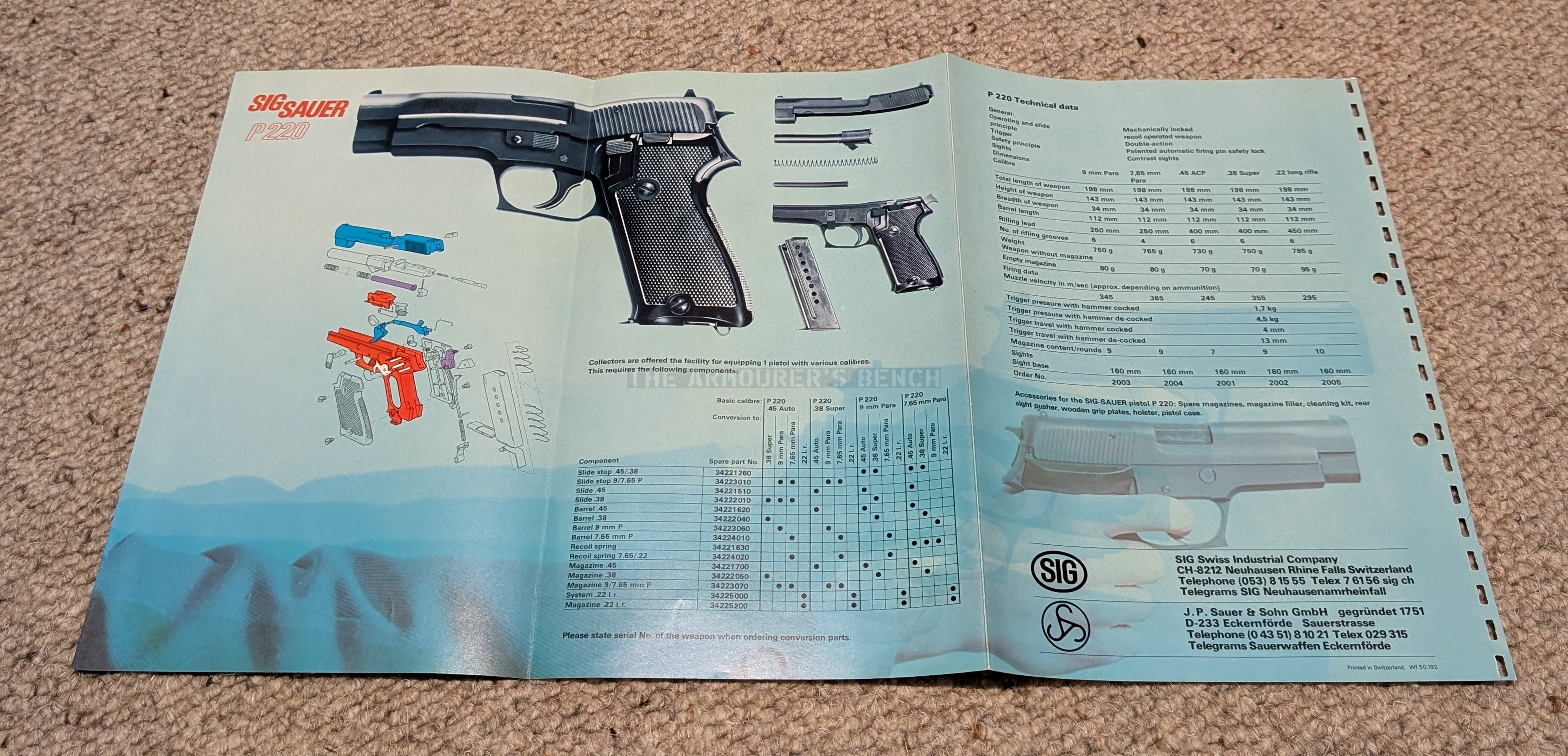
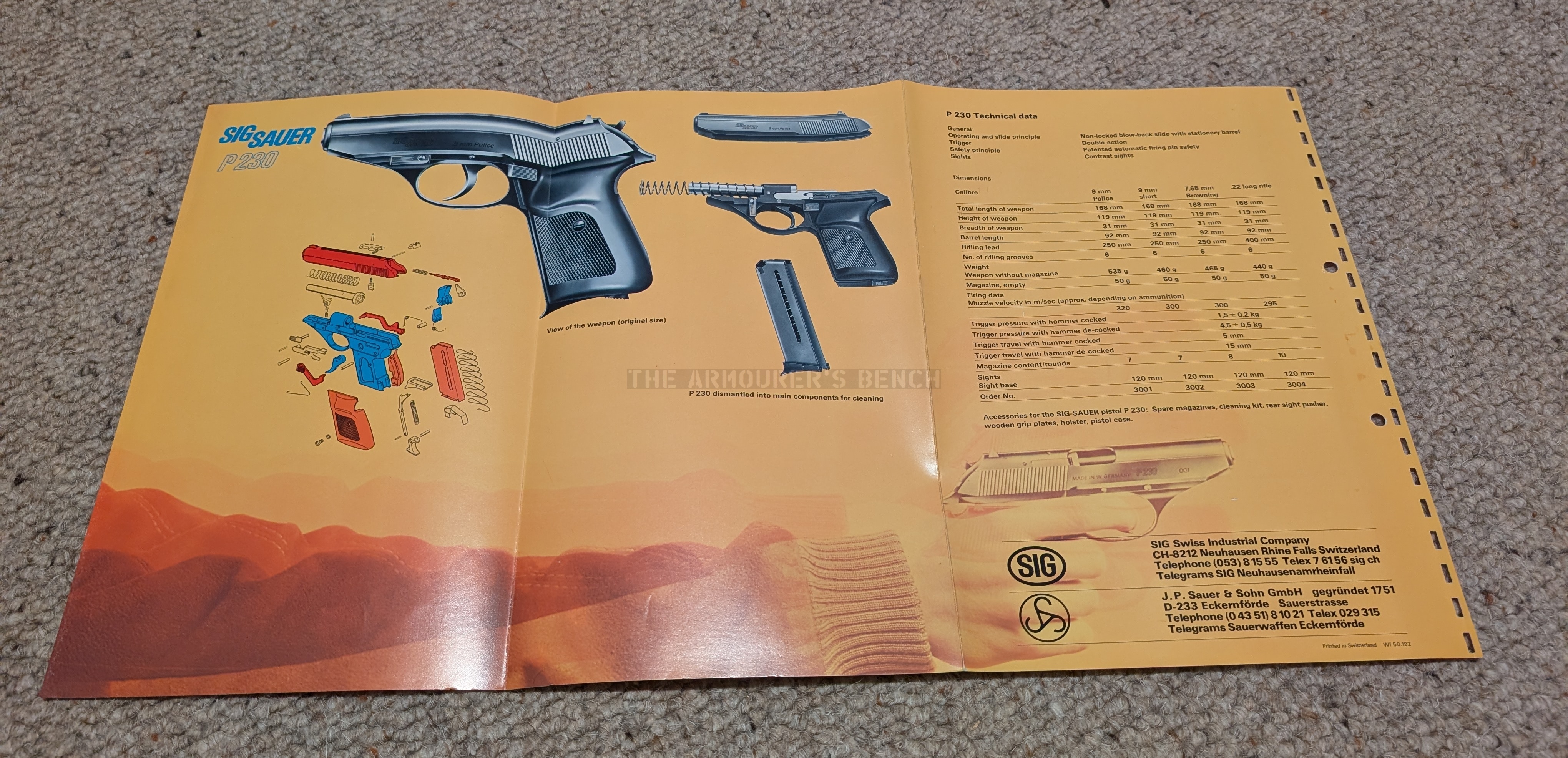
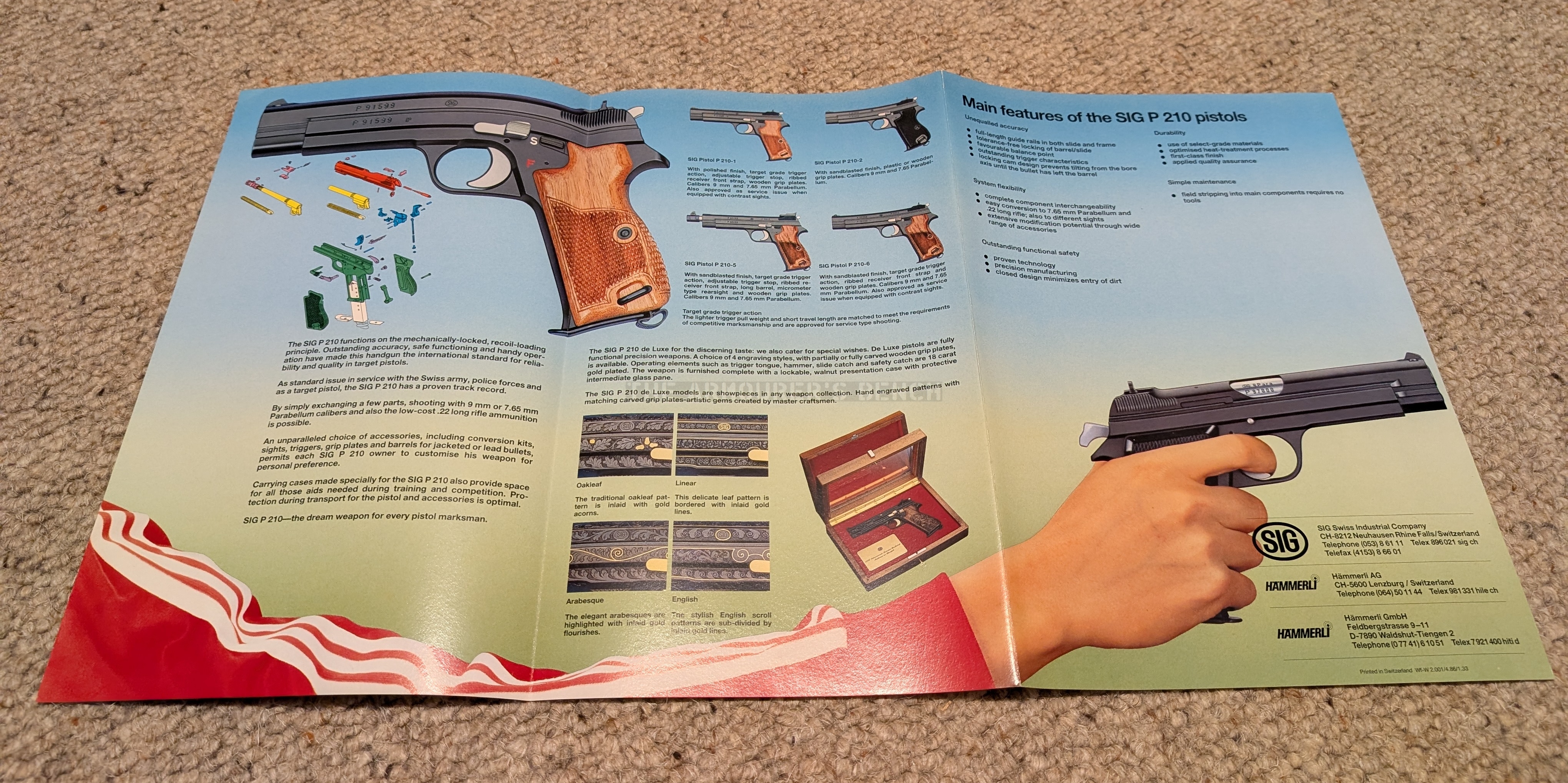
Vintage SIG Sauer Brochures

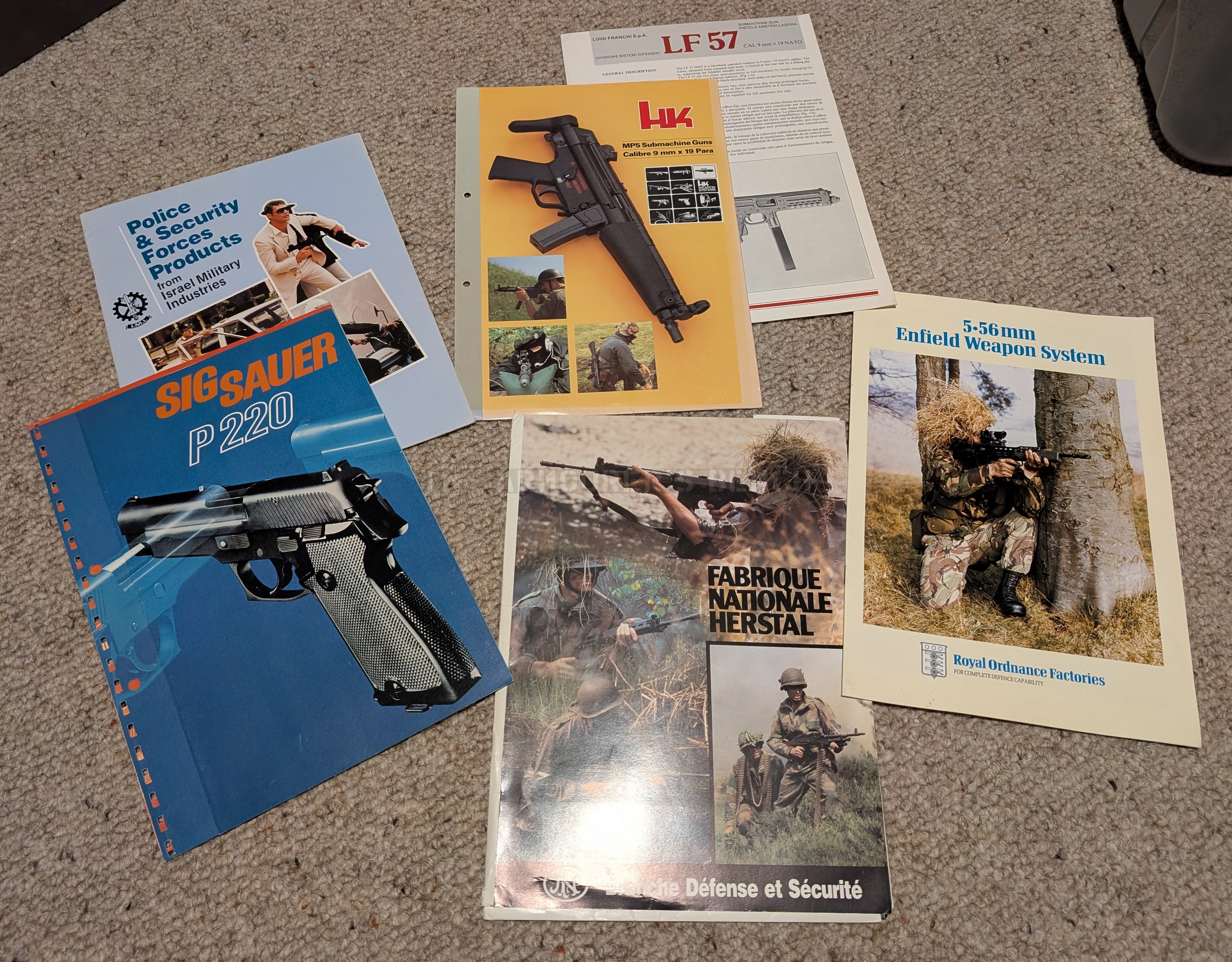
POV – You’re just back from an exciting day walking around the 1989 Arms Expo. You begin unpacking all of the brochures about the latest cutting edge firearms that you picked up! You start with some SIG brochures a nice man from Bern enthusiastically gave you….

More from the TAB reference collection here.


Support Us: If you enjoyed this video and article please consider supporting our work here. We have some great perks available for Patreon Supporters – including early access to custom stickers and early access to videos! Thank you for your support!
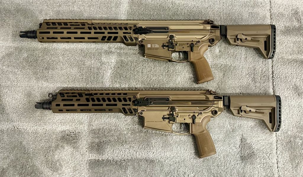
Hands On With SIG Sauer’s XM8 Carbine

Note: This article was published before the US Army announce the classification of the M7 PIE as the XM8.

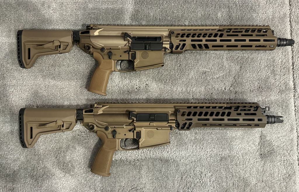
Last week at the DSEI defense exhibition in London, we had the opportunity to handle SIG Sauer’s product improved M7 rifle [now known as the XM8 carbine]. Over the past year, SIG Sauer has taken user feedback from the US armed forces and refined the M7; the result is a handier weapon which feels more like a fighting rifle.

M7 Product Improved, with 10.5in barrel, at DSEI 2025 (Matthew Moss)

One of the key criticisms of the M7 is its weight, with the M7 weighing in at around 9.8 pounds (4.46 kg) with its SLX suppressor. By comparison, the improved M7 weighs in at around 7.5lbs (3.5kg) unloaded, with a suppressor but without an optic. This makes the refined M7 [XM8] a full kilogram (2.2lbs) lighter. 

M7 Product Improved [XM8] at DSEI 2025, with suppressor removed (Matthew Moss)

M7 Product Improved [XM8] at DSEI 2025, with suppressor mounted (Matthew Moss)

SIG Sauer achieved this weight reduction in a number of ways; the barrel has been shortened from 13 to 10.5 inches, and some of the internal components, such as the bolt, have been lightened. SIG explained that the muzzle velocity of the rifle has only been slightly decreased by the barrel length change, with the improved M7 [XM8] achieving around 2,800-2,900 FPS (870 m/s) compared to the 3,000 FPS with the original 13-inch barrel. SIG say this still more than meets the Army’s ballistic and armor penetration requirements. 

M7 Product Improved [XM8] with new shorter SLX suppressor at DSEI 2025 (Matthew Moss)

The barrel itself has a lighter profile, and the handguard has been shortened and reprofiled to match the new barrel length. SIG have also removed the folding stock latch, with the fixed stock saving several grams. Arguably, for some applications, this is weight that could be justified to maintain the ability to fold the weapon’s stock for a more compact profile – better suited for vehicle operations.

M7 Product Improved [XM8] with fixed stock at DSEI 2025 (Matthew Moss)

In addition to a shorter barrel, SIG Sauer has also shortened the SLX suppressor which is paired with the M7, by approximately an inch; this helps improve the rifle’s balance. SIG have also paired the new shorter suppressor with a new lightweight thermal shield, which significantly reduces the heat signature of the suppressor. SIG are also offering a mesh shroud (similar to that seen issued with SURG kits) and an anti-mirage shroud. With the thermal shield, the suppressor’s heat glow under night vision and thermal optics only becomes visible at around 100 rounds, rather than 40 rounds without the shield.

M7 Product Improved muzzle close-up at DSEI 2025 (Matthew Moss)

SIG’s work on the M7 was undoubtedly driven by US military feedback and a desire for refinements, but it is worth noting that it is unclear whether the rifle seen at DSEI will be the configuration the military moves towards in the future. Another variant of the improved rifle, with the shorter barrel and new handguard but a new upper receiver profile, was seen recently at the Maneuver Warfighter Conference 2025 in a released (and subsequently redacted) photo shared by the US Army. The rifle is also seen to be equipped with a Millbrook Strategic Services MFMD suppressor.

M7 Product Improved [XM8] at DSEI 2025 (Matthew Moss)

The US Army now has around 25,000-30,000 M7 rifles in inventory; it is unlikely that rifles already in service will be retrofitted to the new M7 Product Improved [XM8] spec. The iterative refinement of the M7 isn’t a surprise; testing, feedback and improvement are key to the Next Generation Squad Weapons program’s spiral development strategy. As such the M7 and M250 only recently completed desert environmental testing with troops in August. Time will tell if the configuration seen at DSEI (or something similar) is adopted by the US Army to supplement the M7s currently in service. In the meantime questions regarding the M7 PI [XM8]‘s accuracy, reliability, parts wear and signatures are yet to be definitively answered but it is interesting to see the potential direction of refinement the rifle is moving in.

Update – 24/9/25:

A social media video shared by the US Army highlighting a visit by the Secretary of the Army to the 101st Airborne included a brief shot of a board that offered some details on the “M7 PIE” and the “M7 ‘Carbine'”. (H/T to @TangirayL) PIE standing for ‘Product Improvement Effort’.

The board lists the major changes made to the two rifles and gives some weight and length specs on the variants. This would indicate that rather than just one improved variant there are two and the one shown at DSEI is the M7 ‘Carbine’ (or PIE RAPTOR).

Update 14/10/25:

At AUSA 2025 SIG Sauer displayed both the product improved M7 [which SIG refer to as the M7 Enhanced Rifle] and the product improved M7 carbine. Solider Systems Daily shared good side by side photos illustrating the two new versions of the M7. Noteably the design of the handguard between the M7 PIE Carbine seen at DSEI and AUSA differs in their side MLOK configurations.

SSD also reports that: “regarding barrel life. The program requirement was for 5,000 rounds which is the same specification as the M4. However, SIG has noted barrel life for the M7 in excess of 10,000 rounds.”

Update 17/6/26:

XM8 carbine (US Army)

The US Army is reportedly set to stop procurement of the M7 in favour of the XM8. The already delivered M7s (with estimates varying from 40,000 to approximately 60,000) will eventually be replaced by the M8. The future use of the M7s is unclear. Previously the US Army had aimed to acquire 111,428 M7 rifles. It now appears the XM8 will make up around half of this procurement. In April 2026, the US Army announced it has received the first batch of XM8 carbines.


Support Us: If you enjoyed this video and article please consider supporting our work here. We have some great perks available for Patreon Supporters – including early access to custom stickers and early access to videos! Thank you for your support!
16 Vickers Machine Guns in Action – Commemorating the Legacy of the Machine Gun Corps

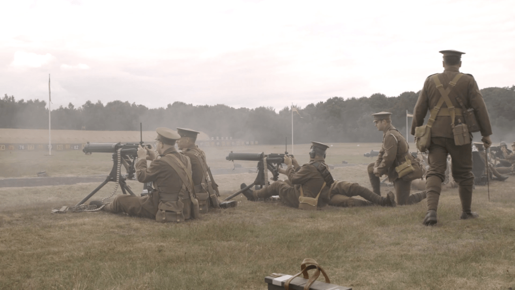
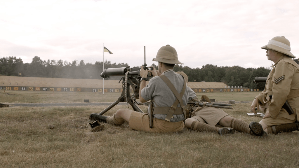
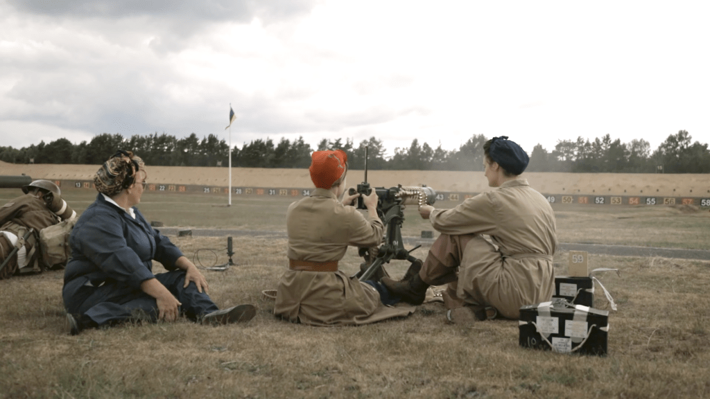
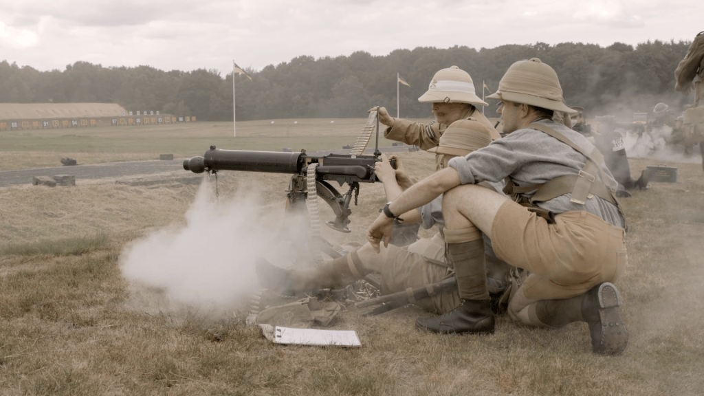
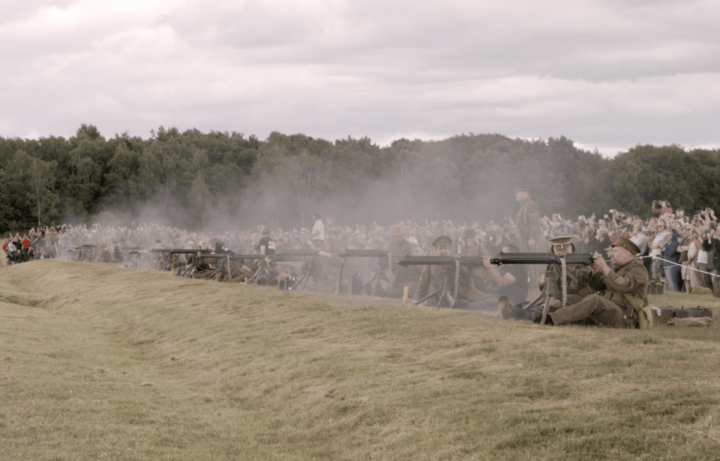
A couple of weeks ago I had the honour of taking part in a shoot at Bisley to commemorate the disbandment of the British Army’s Machine Gun Corps. The Corps was formed in 1915 and disbanded in July 1922. They left an important legacy of skills and doctrine for machine gun use which remains with the British Army today. 

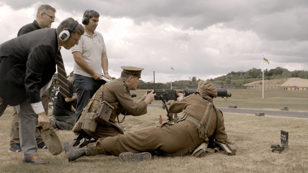
Myself an TJ manning a Nepalese contract Vickers Gun during the shoot. We portrayed members of the Guard Machine Gun Regiment (all photos courtesy of Adam Blackmore-Heal)

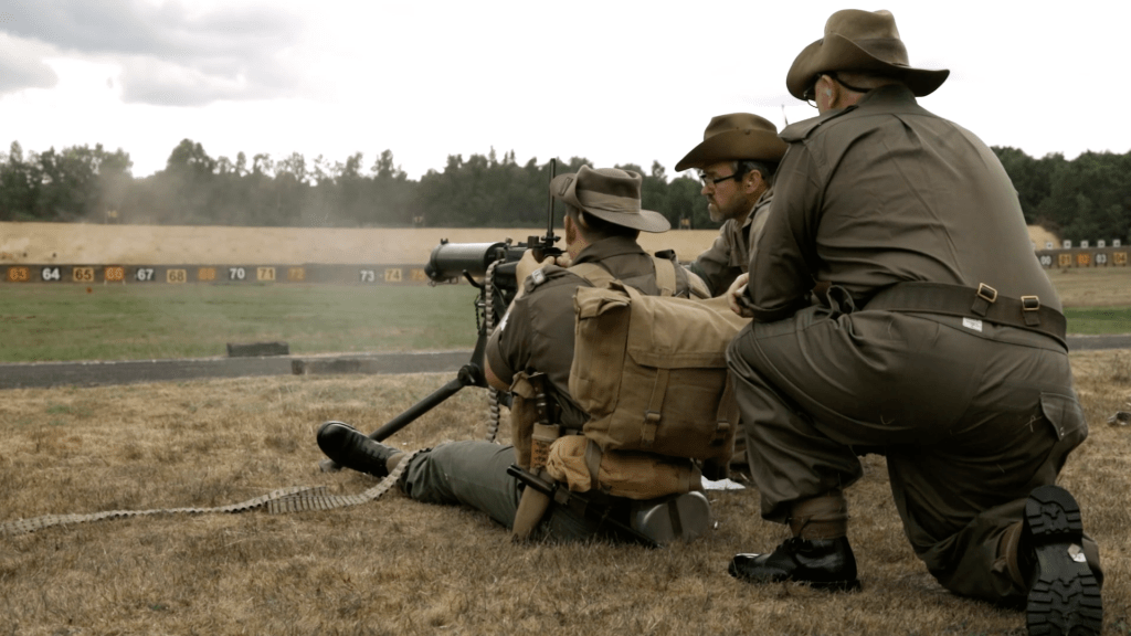
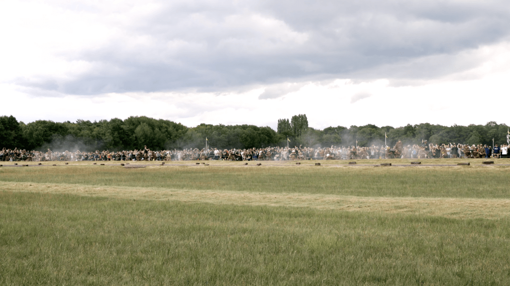
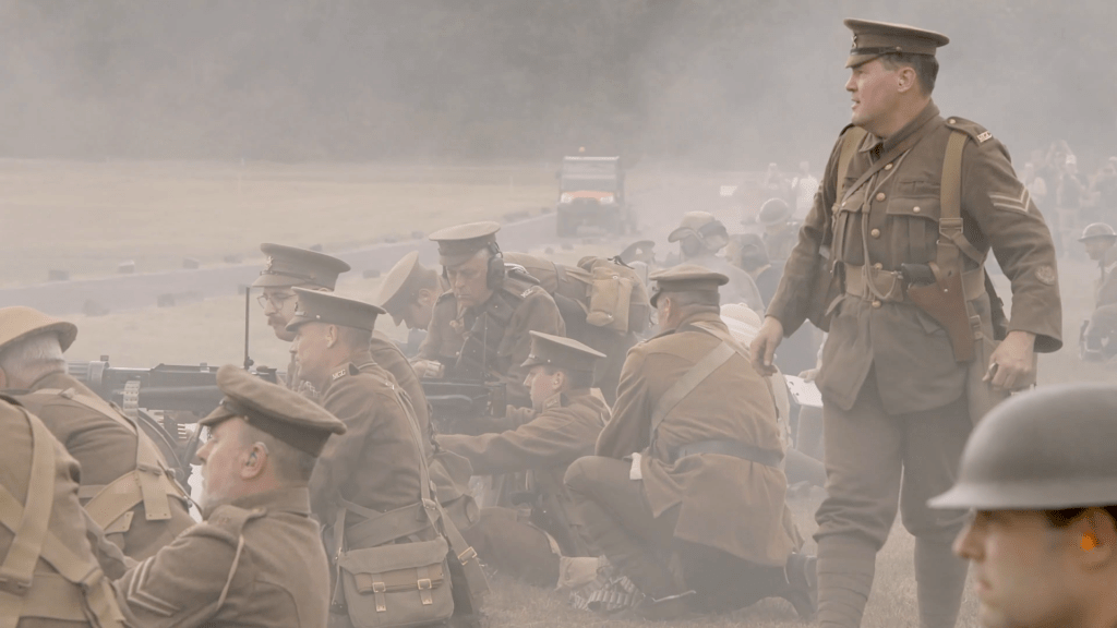
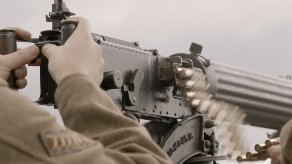
The shoot was organised by my friend Rich Fisher of the Vickers Machine Gun Collection & Research Association. The shoot gathered 16 Vickers Machine Guns, the equivalent of a First World War Machine Gun Corps company.  Each gun represented a different period of the British Army’s use of the Vickers Gun from 1912 all the way through to 1968, when it finally went out of service. 

Here’s some photos from the shoot (courtesy of Adam Blackmore-Heal):

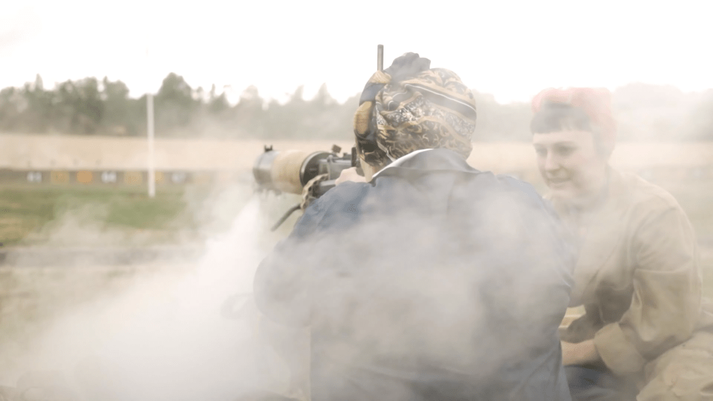
Throughout the day I captured some behind the scenes footage and Rich Willis was kind enough to run my camera for me during the shoot when I had my hands full. This was the first time this many guns had been fired together in 20 years and all in all around 16,000 rounds were fired and over 700 people turned out to watch the event.

Not only did the day illustrate the impressive volume of fire that the guns were capable of but it also put their lethality into perspective. The shoot illustrated the devastation the weapons could bring and the important legacy of the men who manned them.

 I highly recommend visiting the Vickers Machine Gun Collection & Research Association’s YouTube channel to watch the stream of the full 45 minute shoot, a brilliant 360-degree view video which puts you right on the firing point and a really special 20 minute mini documentary about the shoot. 


If you enjoyed this video and article please consider supporting our work here. We have some great perks available for Patreon Supporters – including custom stickers and early access to videos! Thank you for your support!
Home Guard Improvised Incendiary Weapon

On the 14th May 1940, the British Government announced the formation of the Local Defence Volunteers. By the summer of 1940 nearly 1.5 million men had volunteered to serve. The force was later renamed the Home Guard in July 1940 but remained under-equipped throughout the summer of 1940. Many of the newly raised militia units had just ‘LDV’ arm bands, some civilian firearms and improvised weapons, as uniforms and service weapons were in short supply.

I recently came across a really interesting piece of footage showing a Hampshire Home Guard unit training with an ‘incendiary weapon’. With few heavy weapons available during 1940, some Home Guard units improvised. This remarkable original colour footage appears to show a reasonably effective incendiary weapon of some sort. But beyond what we can see we know very little about the weapon.

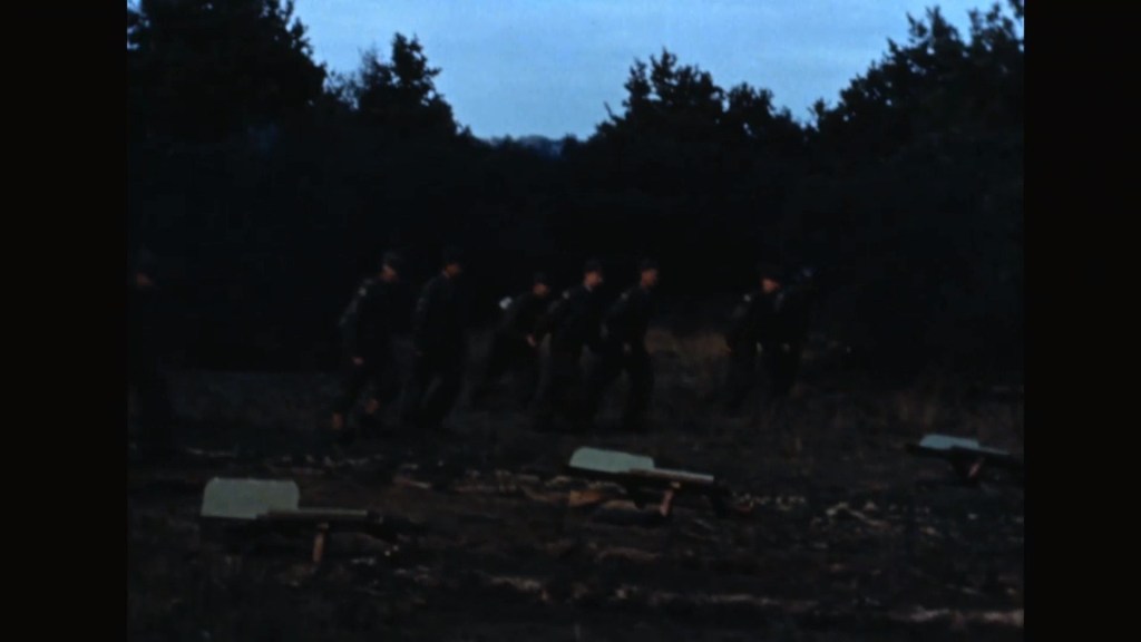
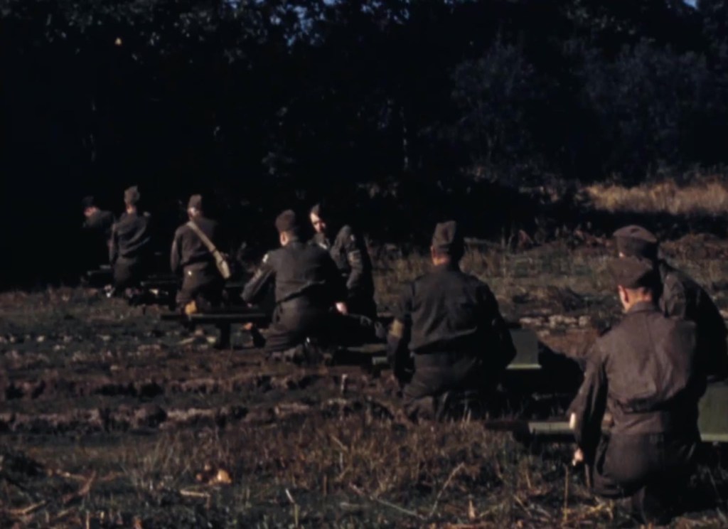
The footage shows a battery of five launchers, each seemingly with a 3 man crew. One man aiming, another loading and another firing. The footage is undated but from their arm bands we can see that the men are Home Guard so definitely post July 1940. The men also appear to be quite well equipped with caps, denim trousers and blouses and belts. No webbing is seen but we can potentially date the footage to between late 1940 and mid-1941.

Crews dash to their launchers. Note the rifle stock-shaped pieces to the side of the weapons which appear to have been used to aim the launcher

The incendiary weapon itself is extremely intriguing! I haven’t seen a similar weapon before and I couldn’t find any direct reference to it in the available original documents, newspapers or photos. The footage comes from the Wessex Film and Sound Archive, it is described as showing Home Guard men from Swanmore, a rural village in Hampshire, demonstrating the weapons. Before the incendiary weapon is demonstrated we see a company sized force of Home Guard parading, without rifles or other equipment, and then a single Home Guard member demonstrates loading an SMLE. From the footage we can get an idea of how the weapon would have worked.

Three-man crews sit by their weapons note the troughs projecting from the front of the launchers

The men run to the launchers, which appear to be made of wooden boards. Beneath them are rifle stock shaped pieces which the man at the rear seems to shoulder – probably to aim the weapon. The other two crew members kneel either side of the launcher. The footage then cuts away to another angle from the other side and shows one of the kneeling men hitting the rear of the projectile with a hammer. Then with a flash and puff of smoke the projectile launches forward. The man who aimed the weapon appears to have moved away, out of shot. Frustratingly the footage is a bit underexposed and quite dark so we can see too much more detail but we can see that the chap with the hammer is definitely hitting the rear of what looks like a length cylinder. The cylinder shoots to the rear while a projectile fires forward and the launcher’s crew look downrange.

A somewhat low resolution close-up of the launcher. Note the crew member lying behind it aiming it along the wooden piece on the right. The projectile and launch cylinder sit in a trough while behind appears to be a shield to protect the crew member aiming

We then get footage showing what seem to be a series of impacts, likely from the projectile’s fired by the launchers. Then we get another clip of the men running to man the launchers and some more shots of the incendiary weapons exploding. From the available footage its pretty difficult to theorise how the launchers work. They appear to be using an almost proto-recoilless rifle-like principle with the launch cylinder shooting backwards and the projectile leaving the cylinder and firing towards the target. The crew member with a hammer may be hitting a percussion cap to detonate some black powder which projects the incendiary bomb. This system may have been developed to remove the need for a fixed, pressure bearing barrel. Making the weapon much simpler to manufacture.

The effect down range – the target well alight

The footage doesn’t give us too much indication of the range of the weapon but it’s distant enough that the men firing the weapon don’t appear to recoil when the projectile hits the target. The incendiary effect downrange is actually quite impressive and a battery of five of the launchers would have been an impressive sight and perhaps quite useful as a road ambush weapon which was something the Home Guard focused heavily on at the time.
It wasn’t until later in 1941 that sub-artillery like the Smith Gun, Northover Projector and the Blacker Bombard began to enter service with the Home Guard. Until then some of the units took it upon themselves to create their own weapons, improvising contraptions like the one featured in this video.

Update 28/07/21:

The weapon somewhat fits the description of the ‘Jones-Wise Projector’ shared by David Lister in his book Forgotten Tanks and Guns. Thanks to BettongMI who brought this to my attention in the comment section of the video. The weapon was apparently developed by a pair of Home Guard officers and while turned down for regular service was used by some elements of the Home Guard in southern England, at least until official sub-artillery began to enter service.


If you enjoyed this video and article please consider supporting our work here. We have some great perks available for Patreon Supporters. You can also support us via one-time donations here. Thank you for your support!


Bibliography

Home Guard and home-movies in Swanmore, Wessex Film and Sound Archive via the BFI, (source)

Britain’s Final Defence: Arming the Home Guard, 1940-1944, D. Clarke (2016)

Forgotten Tanks and Guns of the 1920s, 1930s and 1940s, D. Lister (2018)

Mousqueton Arcelin Modèle 1856

By the mid-19th century many major militaries were beginning the hunt for a reliable and robust breechloading system. France was no exception with a number of systems trialled during the 1850s, following the Prussian adoption of the Dreyse rifle. Today we’re lucky enough to be examining one of France’s early breechloaders , with some interesting features – the Arcelin.

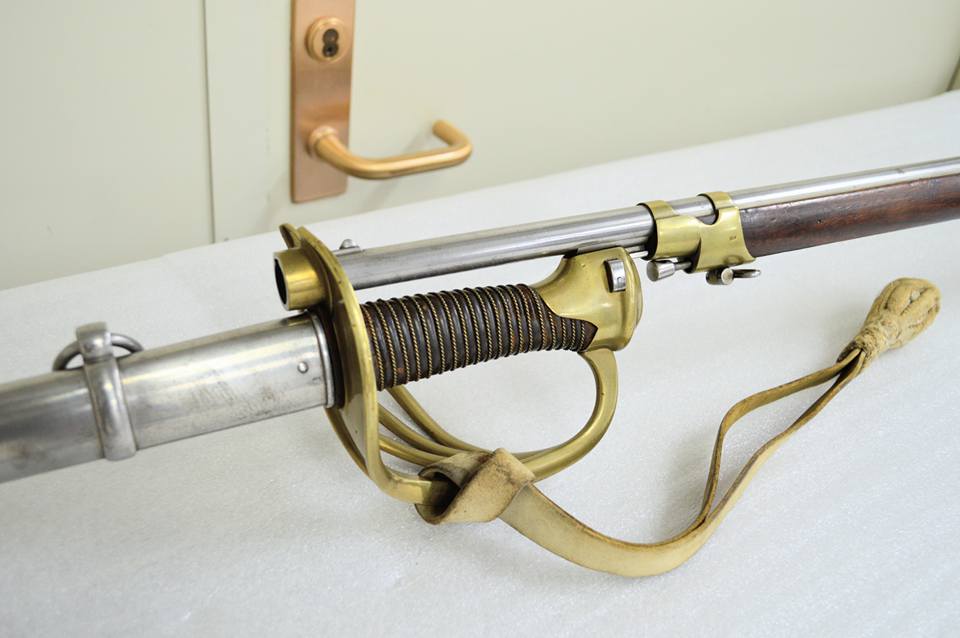
Arcelin carbine and bayonet (Danny Michael/CFM)

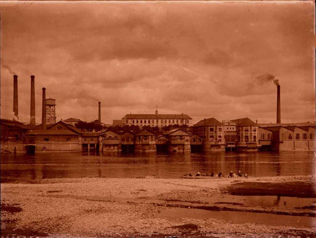
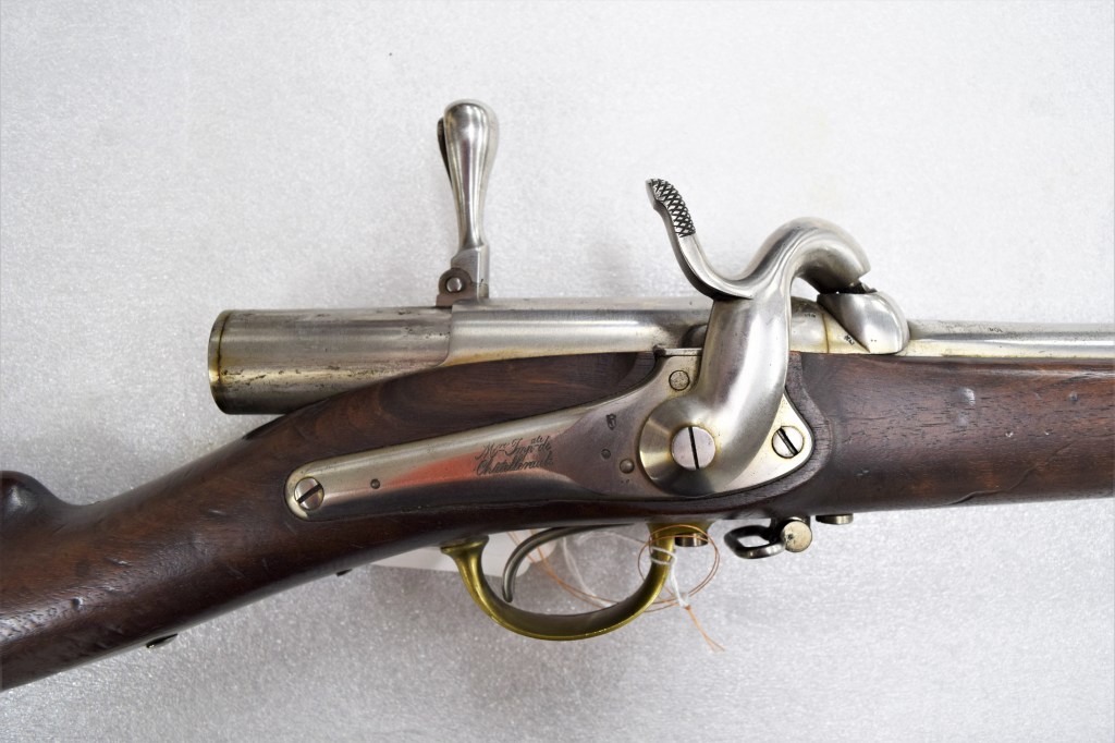
Perhaps properly described as le Mousqueton Arcelin 1856, the carbine has the distinction of being the first French breechloader to have a distinct bolt handle. Designed by Charles Arcelin, a graduate of the École spéciale militaire de Saint-Cyr and veteran of the Napoleonic Wars. In the 1820s Arcelin began his ordnance career working in arms factories in Mutzig, Saxony and Starsbourg. In 1839 he became deputy director of the Tulle arsenal and developed a system for the conversion of flintlock muskets to the percussion system in 1842. He subsequently became Director of the Châtellerault arsenal between December 1841 to September 1842 and again from December 1849 to August 1852. It was during this period that Arcelin developed his breechloader.

Manufacture d’Armes de Châtellerault (Châtellerault museum)

Following his work on developing a percussion conversion Arcelin set about developing a breechloading system, in June 1853 a prototype cavalry carbine was tested at Vincennes. The prototype fired 130 rounds before its action fouled and seized up – despite this observers were impressed, including Emperor Napoleon III.  

A letter from the Cabinet of the Emperor, dated August 4, 1856 states:

“The Emperor wants General Arcelin to be responsible for having the Manufacture de Châtellerault make 300 carabiners with a movable breech of the model which has been tested at Vincennes and which gave satisfactory results and in addition 100 reserve cavalry sabers, 100 line cavalry sabers and 100 light cavalry sabers which will be attached at the end of the carabiners. The sabers as well as the carabiners of a new model which was established on the personal indications of the Emperor. These weapons are intended to be tested in three regiments of the Imperial Guard.”

At the beginning of October, the Emperor ordered that production be reduced to 100 rifles. On the 7th October, it was proposed that Châtellerault would provide 108 carbines and sabers. A manufacturing report dating from 5th April 1857, signed by Arcelin, specified that 111 carbines and sabers had been produced. Despite this sources suggest that by June 1857, carbines was reduced again by the French war ministry, to 96 – a total of 32 per regiment. The carbine we are examining is marked with ‘108’ in a number of places, this would support the total of 108 and would also make it the last of the trials prototypes manufactured.

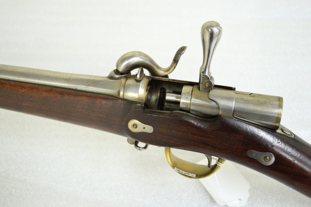
Bolt handle extended with the action partially open (Danny Michael/CFM)

While some sources refer to the sabres as sabre-lances, this was not their designation or purpose nor were the weapons ever issued to Napoleon’s Squadron des Cent-Gardes as some sources suggest. Instead they were issued to three regiments of cavalry:

The reserve cavalry’s 1st Carabinier Regiment (Cavalerie de Réserve, 1er Régiment de Carabiniers), the line cavalry’s Empress’ Dragoons (Cavalerie de ligne, Dragons de l’Impératrice) and the 1st Hussar Regiment of the light cavalry, (Cavalerie légère, 1er Regiment de Hussards).

Once the contract for 108 trials carbines had been confirmed Arcelin set about refining and producing the guns at Châtellerault. He recruited a promising young gunsmith, Antoine Chassepot, who had been working at the arsenal since 1851, to work on the project. What Chassepot’s input on the project was is largely unknown although his work with Arcelin clearly influenced his own later designs.

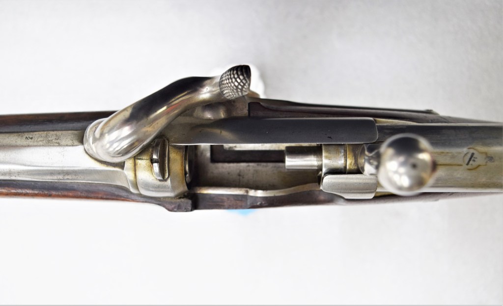
The Arcelin carbine used a paper cartridge with a 21g (or 324  grain), 12mm projectile propelled by 3g (or 46gr) of black powder. It was still ignited by a percussion cap and had a back action lock. The breech locked by a pair of opposing threaded screws and by a lug in the base of the action. The carbine weighs 3.2kg (just over 7lbs) and was 1.18m (46.4in) in length, with a 76.5cm (30in) barrel.

A close up of the breech with action open (Matthew Moss)

To operate the carbine first the action is opened, rotating the bolt handle up 90-degrees. A cartridge would then be slide into the breech and the action pushed forward and closed. The percussion lock would then be brought to half-cock, a cap placed on the nipple and then the lock would be brought to full cock and the weapon fired. As the carbine fired a paper cartridge there was no need for extraction of a spent case.

The trial of the carbine was carried out alongside another new breechloader, a pinfire, falling block action developed by Antoine Treuille de Beaulieu, chambered in a 9mm round. General Treuille de Beaulieu is perhaps best known for his rifling system for artillery.

The carbines and sabres were issued and ready to begin trials at the beginning of April 1857. By the Autumn of 1857, following testing by the various units the Arcelin was rejected. The Artillery Commission found that the lack of obturation at the breech lead not only to gas escaping the action and being unpleasant and somewhat dangerous for the user but also the fouling of the interrupted thread which locked the action led to jamming and in a number of cases the folding bolt handles were broken when troopers attempted to force the actions open.

The Arcelin carbine with a similar but later pattern of sabre-bayonet (Danny Michael/CFM)

Now for the rather impressive bayonet. We have examined carbines with significant bayonets, like the Durs Egg-made Crespi breechloader. The French had a penchant for sabre bayonets dating back to 1840s and would continue to use them into the 1870s. The sabre seen with this carbine is not the exact pattern which would have been paired with the Arcelin. The 1856 pattern Arcelin sabre which would have mounted on the carbines have a hilt style which is slightly different and the lug under the barrel doesn’t quite interface with the catch on the sabre.

The sabre itself is based on the Mle 1854 sabre, a double fullered, 1m long, straight sword manufactured, like the carbines, at Châtellerault. The sword with this carbine is marked at ‘Dragon Mle 1854’ suggesting it was issued to a dragoon regiment, who only began receiving the Mle 1854 in the mid-1860s, the blade’s markings support this as it is also marked June 1865.

From the final report on the trials of the Arcelin we gain some insight into how the sabre-bayonet was to be used. In their final report, in October 1857, the Hussars noted that when used as a bayonet the sabre could only practically be used on foot describing use on horseback as impossible. They felt that firing the carbine could only accurately be done at short range as the fixed sabre made the carbine ungainly, heavy and unbalanced.

Right side view of the Arcelin’s back action percussion lock, with its action open (Matthew Moss)

The units did, however, appreciate the defence the sabre-bayonet offered to a dismounted trooper. A passage from the translated report reads:

“the use of the saber as a bayonet gives man a means of defense which he did not have with the old weapons. This straight saber is light, perfectly in hand and excellent for pointing (…) The firing of the new weapon, saber at the end of the barrel, was carried out with the hussars and did not give place to any important observation. As expected, the shot becomes less fair because the weapon is too heavy and less well maintained by the rider (…) The saber used as a bayonet makes it a powerful weapon.”

It appears that 60 of the sabre-bayonets were later adapted to be mounted on the Saint Etienne-built 1858 Chassepot breechloading carbines which were subsequently trialled. These carbines still used percussion caps but had a fixed bolt handle, a rubber obturating round near the bolt head and the actions was rear-locking. This system would eventually evolve into the Fusil Modèle 1866 – the Chassepot.

Gas obturation was a key issue for many of the early breechloaders and would be for some time. General Arcelin’s carbine can be seen as an important footnote in the development of the Chassepot rifle which would follow it. The general died in 1868, aged 73.


If you enjoyed these videos and this article please consider supporting our work here. We have some great perks available for Patreon Supporters. You can also support us via one-time donations here. Thank you for your support!

Bibliography:

‘Le Sabre du Mousqueton Arcelin’, Gazette des Armes, #156, Aug. 1986, P. Renoux
‘Le Mousqueton Arcelin 1856-1858’, Gazette des Armes, #77, Dec. 1979, P. Lorain
‘Le Sabres-lances Arcelin Mle 1856 Trois Modeles Particuliers Pt.1’, Gazette des Armes, #397, Apr. 2008, B. Aubry & C. Bera
‘Le Sabres-lances Arcelin Mle 1856 Trois Modeles Particuliers Pt.2’, Gazette des Armes, #398, May. 2008, B. Aubry & C. Bera
‘Le Premier Chassepot – Le System de 1858’, Gazette des Armes, #78, Jan. 1980, P. Lorain
L’Arme a Feu Portative Francaise M. Cottaz (1971)

Gulf War: Operation Granby Iraqi Weapons Recognition Guide

In this video we’ll be launching a brand new series where we’ll look at period small arms and light weapons manuals and other ephemera like infantry tactics handbooks and recognition guides.

This month marks the 30th anniversary of what the British Army called Operation Granby, better known as Desert Storm or the Gulf War.  So I thought taking a look at a Recognition Guide to Iraqi Ground Forces issued during Granby would be a good place to start!

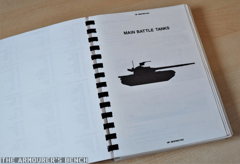
Chapter page for Main Battle Tanks (Matthew Moss)

Britain deployed more than 53,000 personnel during the operation, which began in August 1990, just after the invasion of Kuwait, with the arrival of 2 squadrons of Tornados in theatre. The first ground forces, elements from 7 Armoured Brigade began arriving in October. With no ready reaction force a division strength force was cobbled together from units deployed in Germany and the UK. Huge logistical constraints were overcome to provide a full armoured division, consisting of two brigades, for the liberation of Kuwait.

The guide’s entry for the AMX 155 F3 (Matthew Moss)

During the ground phase of the operation (Operation Desert Sabre), which began on 24th February 1991, British armoured and mechanised forces, part of VII Corps, provided the left-hook of the allied assault. The division’s two armoured brigades leapfrogging one another quickly taking successive objectives and sweeping west through occupied Kuwait, towards the Gulf Sea, neutralising Iraqi positions with relative ease. During less than 100 hours of ground combat British forces travelled 180 miles and destroyed approximately 300 Iraqi vehicles while allied forces as a whole captured an estimated 80,000 Iraqi troops. A total of 47 British troops were killed during Granby. A ceasefire was declared on 28 February with Iraqi forces collapsed and Kuwait liberated.

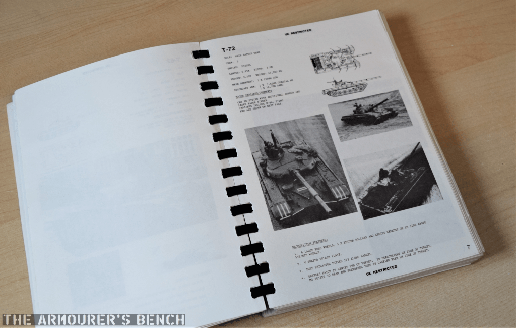
The guide’s entry for the T72 tank (Matthew Moss)

The guide was compiled by the Recognition Materials Cell at the Joint Air Reconnaissance Intelligence Centre (or JARIC). Formed in 1953, from the Central Interpretation Unit and based at RAF Brampton from 1957 to 2013, JARIC was the UK’s strategic imagery intelligence provider – providing analysis of aerial and later satellite photography or enemy assets.

With war with Iraq looking imminent and substantial British forces deployed from the UK and Germany, JARIC were tasked with putting together a recognition guide covering Iraqi and Kuwaiti ground assets captured by Iraq during the invasion of Kuwait.

The infamous SCUD (Matthew Moss)

This included everything from main battle tanks, reconnaissance vehicles and armoured personnel carriers to self-propelled artillery, mortars, artillery and multi-barrelled rocket launchers. It also included anti-tank missiles, surface to air missile systems and anti-aircraft assets as well as engineering equipment. All of which might be encountered during upcoming operations to liberate Kuwait. Let’s take a look.

The guide sadly doesn’t have a scale of issue list so it’s difficult to know how many were printed or  which units received them. But the first page does give us some indication of the material’s sources – noting they are from unclassified and restricted sources – giving the book a restricted classification overall.


If you enjoyed these videos and this article please consider supporting our work here. We have some great perks available for Patreon Supporters. You can also support us via one-time donations here. Thank you for your support!

Bibliography

The Gulf War 1991, A. Finlan (2003)

Hot War, Cold War, C. McInnes, (1996)

‘Joint Air Reconnaissance Intelligence Centre (JARIC)’, National Collection of Aerial Photograph, (source)

‘Unit History: Joint Air Reconnaisance Intelligence Centre’, Forces War Records, (source)

Cold War British Vehicles – Anglesey Transport Museum

Late last summer we visited the Anglesey Transport Museum in North Wales. They had a great collection of classic and vintage cars and bikes and most interestingly they had a little collection of British military vehicles.

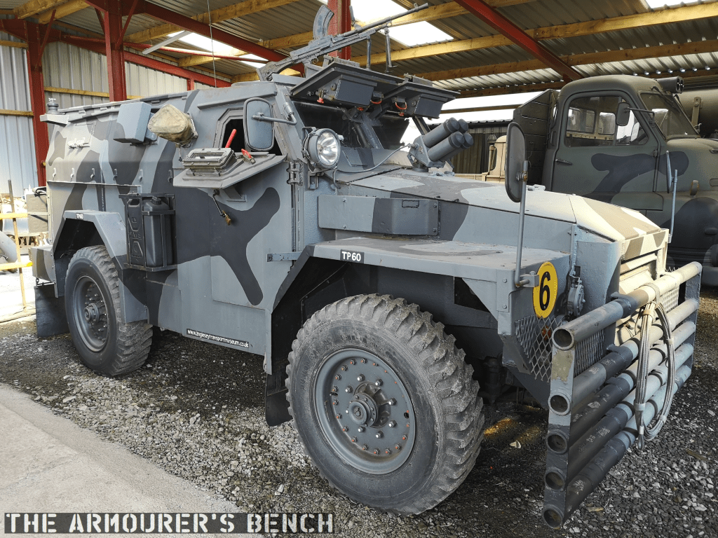
They had a number of trucks and special purpose vehicles from the Royal Engineers, REME and RLC and even a Green Goddess Fire Engine. They also had a couple of pretty cool Cold War British Army armoured personnel carriers.

Alvis Saracen

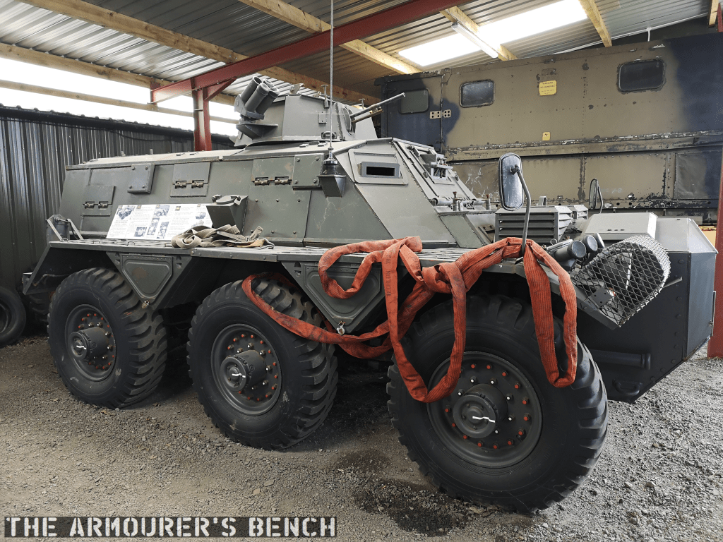
Alvis Saracen (Matthew Moss)

The Saracen was a six-wheeled armoured personnel carrier (APC) built by Alvis. It entered service in 1952 and was used extensively in Malaya and Northern Ireland. The Saracen could carry an 8 man section along with its 2 man crew. It had a 160HP Rolls Royce engine and depending on when during its service life its turret could be mounted with a .30 calibre M1919A4 or an L37 vehicle-mounted general purpose machine gun.

Humber Pig

Humber Pig (Matthew Moss)

Another APC which was in service alongside the Saracen, the ‘Truck, Armoured, 1 Ton, 4×4’, better known as the Humber Pig. Based on a truck chassis, it had a 120HP 6 cylinder engine and room for 6 men on the benches in the back. It could be mounted with an L4 Bren gun. It saw extensive use in Northern Ireland during operation Banner and was in service from 1956 through to the early 90s.

Daimler Ferret Mk1 Scout Car

Daimler Ferret (Matthew Moss)

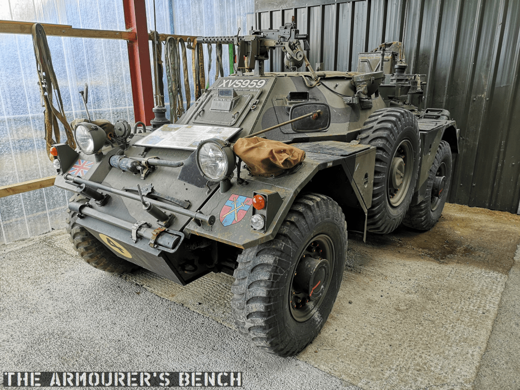
Next to the Pig in the collection was a Mk1 Daimler Ferret scout car. Fitted out with an M1919A4 and six forward-firing grenade launchers – for smoke grenades. The later Mk2 had a turret but the Mk1 made use of its low profile. This one has its canvas cover over the fighting compartment. The 4×4 Ferret was powered by a 130HP Rolls Royce B60 straight six. Perfect little run-around to do the shopping in.

On the top of the hull is the pintle mounted Browning M1919A4 machine gun. This would have been operated by the Ferret’s commander. We can see the mount allows it to be aimed and fired from somewhat inside the hull. The Ferret entered service in the early 1950s and remained in use into the late 1980s/early 1990s. Just short of 4,500 Ferrets were manufactured.

Bofors QF 40mm Mk1

QF 40mm Mk1 (Matthew Moss)

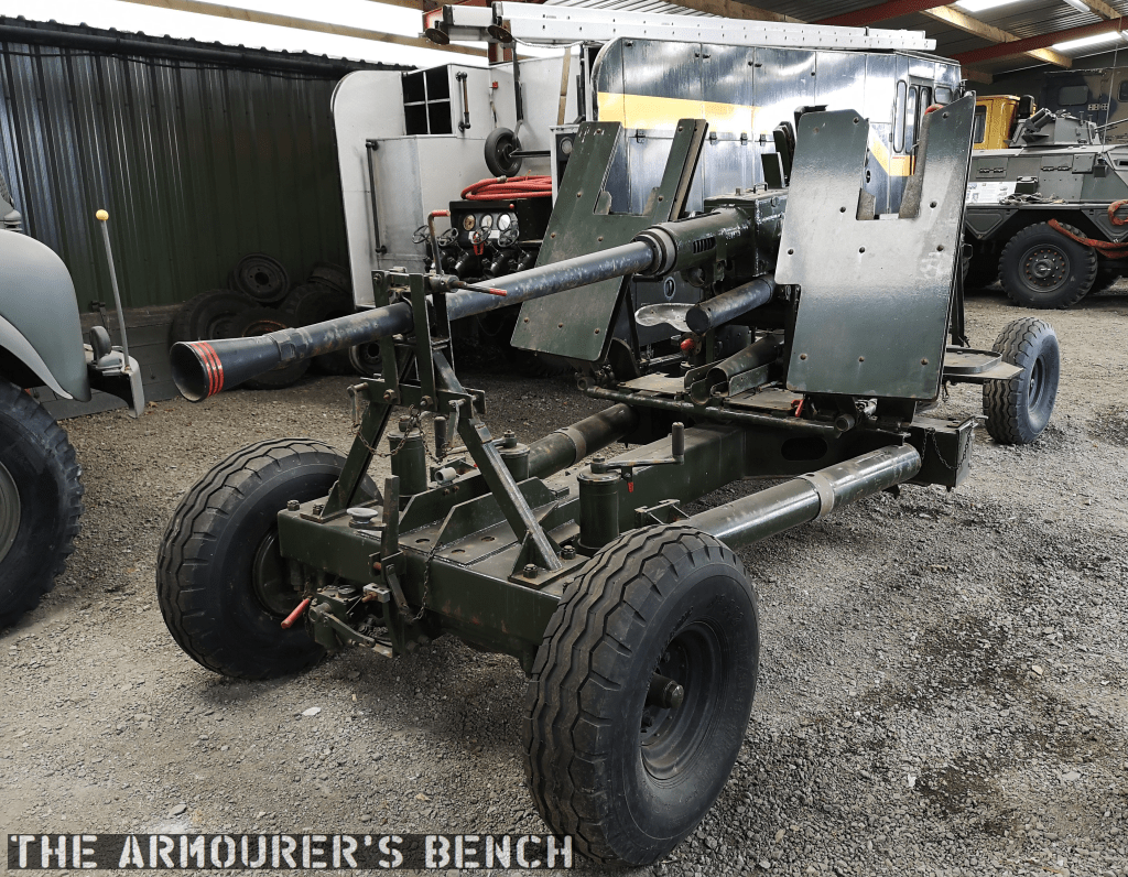
At the centre of the military vehicle collection was a QF 40mm Mk1, better known as a Bofors. Both land and naval versions of the Bofors were used during the Second World War and after. Capable of firing 120 40mm shells per minute, it was normally manned by a four man crew. It filled the British army’s light Anti-Aircraft gun role and remained in service well into the 1980s.

We can see the gun’s huge recoil spring and to the rear of the gun is a case deflector which connected with a trough which channels the spent cases down below the gun. The gun still has most of its controls and traverse and elevation crank handles in place. On top of the gun are the huge guides for the four-round clips of 40mm shells.

Find out more about the museum here.


If you enjoyed these videos and this article please consider supporting our work here. We have some great perks available for Patreon Supporters. You can also support us via one-time donations here. Thank you for your support!


John Browning’s 1895 Slide-Action Prototype

By 1895 Winchester had been considering a slide-action rifle for some time, in 1882 William Mason had begun work on one (US Patent #278987) to counter Colt’s slide-action Lightning only to drop it. Finally in 1890, Winchester introduced a slide-action .22 calibre rifle developed by John Browning. The Model 1890 became extremely popular.

Between 1887 and 1895 Browning patented four slide-action rifle designs. The first of these, US patent #367336, was granted in July 1887, this was followed in 1888 by US patent #385238. In September 1890, the Browning brothers were granted US patent #436965, which along with the previous 1888 patent protected what became the Model 1890. Three years later Winchester introduced the Model 1893 pump action shotgun, that would eventually evolve into the famous Winchester Model 1897.

Right-side close up of the rifle with its action open (Matthew Moss)

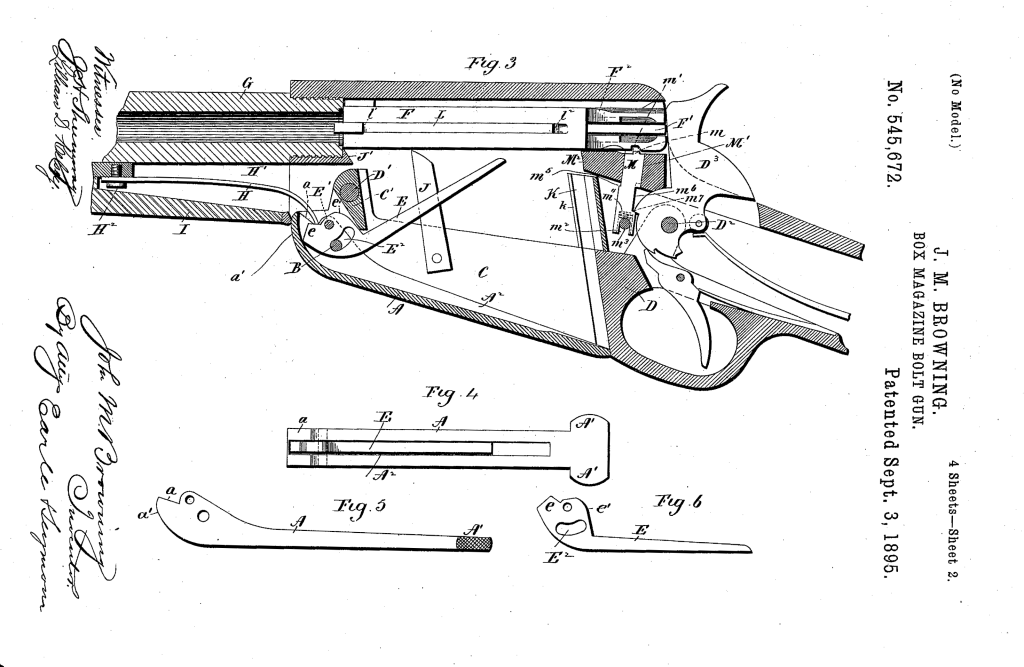
Finally, April 1895, Browning filed a patent for a design for a .30 calibre rifle which was granted in September 1895 (US patent #545672) This patent covers the rifle we’re examining here. The rifle itself is a slide or pump action in long barrelled configuration which Winchester described as a ‘Musket’.

The September 1895 slide-action design was purchased by Winchester but like so many other Browning designs, it never entered production and Winchester purchased the design purely to secure it and prevent other rival manufacturers picking it up. Winchester instead went with a lever-action design, patented in November 1895 (US #549345), which became the famous Winchester Model 1895.

A left-side view of the rifle’s receiver with Browning’s patent overlaid (Matthew Moss)

The September 1895 slide or pump-action rifle design had a laterally camming locking breechblock. As we can see, externally Browning’s toolroom prototype looks somewhat similar to the contemporary Winchester Model 1895, with a single-stack integrated box magazine but with a pump sleeve rather than a lever. 

An action-bar connects the slide/pump to the front of the breechblock/bolt carrieron the right-hand side of the rifle. The slide handle itself is made of a U-shaped piece of metal which wraps around the rifle’s forend. The slide has been roughly cross hatched to improve grip. There is a channel cut into the furniture for the action arm’s attachment point to travel. The slide is attached to the arm by a pair of screws.

A close up of the rifle’s slide/pump handle (Matthew Moss)

However, Browning developed this prototype to allow loading of the magazine from below rather than through the top of the receiver. He added a hinged floor plate, with a spring loaded follower, that allowed loose rounds to be dropped into the magazine and then closed.

As we open the magazine, hinging the cover plate down, we see the carrier flip down against the plate to allow loading. The rifle was designed to be loaded from below with the bolt forward.

Browning’s September 1895 patent (US Patent Office)

In the patent description Browning explained that his aim was to improve breech-loading box-magazine firearms by designing:  

“…a simple, compact, strong, highly effective, and safe gun, containing comparatively few parts and constructed with particular reference to provision for charging the box-magazine with cartridges from the bottom of the frame of the arm while the breech-bolt is in its closed position, so that the arm may be charged without operating its action mechanism or disturbing the cartridge in the gun-barrel, if one is there.”

Browning’s September 1895 patent (US Patent Office)

From the original patent drawings we can see the flat spring which acted on the carrier running below the barrel, ahead of the magazine. Inside the magazine are a pair of what Browning refers to as ‘spring fingers’ these act on the cartridges inside the magazine and keep them properly aligned, seen here in Fig.7 of the patent. In Fig.8 we can see what Browning calls a ‘box-like guideway’ which guide the rims of the cartridges, “preventing the cartridges from being displaced while being fed upwards.”

The rifle’s breechblock locked into a recess in the left side of the receiver, tilting at an angle with the rear of the breechblock canting to the left. When the pump handle was pulled rearwards the breechblock cammed laterally to unlock the action, extracted and ejected any spent casing and when the slide/pump was returned forward a new cartridge was picked up from the magazine, chambered the breechblock locked again ready to fire. The rifle’s hammer was cocked by the rearward movement of the breechblock.

A left-side view of the rifle with its action open, note the complex machining on the rear of the breech bolt (Matthew Moss)

Externally, the slide-action’s receiver looks similar to that of the production Model 1895 but internally they are very different. The action is certainly less open than the Model 1895’s but the lateral locking mechanism is less robust. Additionally, with no lever, as in the Model 1895, the slide-action rifle lacks the safety mechanism which prevents the action from opening accidentally.

A view inside the open magazine with the floorplate hinged open (Matthew Moss)

The model is in the white and while externally the machining and tool work is very neat, inside the action we can see where the cuts in the receiver wall have been more crudely made. In terms of design, the slide-action prototype was certainly simpler and had fewer working parts than the Model 1895 lever-action.

Winchester purchased the .30 calibre slide-action design but never produced it, it is believed that only Browning’s prototype was built to prove the concept. The prototype was part of Winchester’s collection and may now be found at the Cody Firearms Museum.

Check out our earlier videos on Browning’s lever-action box magazine-fed prototype and his en bloc clip-fed prototype.


If you enjoyed the video and this article please consider supporting our work here. We have some great perks available for Patreon Supporters. You can also support us via one-time donations here.


Bibliography:

‘Box Magazine Bolt Gun’ J.M. Browning, US Patent #545672, 3 Sept. 1895 (source)

‘Box Magazine Firearm’, J.M. Browning, US Patent #549345, 5 Nov. 1895 (source)

John M Browning: American Gunmaker, J. Browning & C. Gentry (1964)

Winchester Repeating Arms Company, H. Houze, (2004)

Screw-Breech Percussion Rifle Prototype

In this video and article we’ll examine a somewhat mysterious screw breech percussion rifle – if you, like me ever wondered what a Ferguson with a percussion lock might look like then you’ll find this one fascinating. If you haven’t seen our earlier video on Patrick Ferguson’s 18th century breechloading rifle, check that out!

Right profile of the rifle (Matthew Moss)

This rifle likely dates to the mid-1860s and from some research is believed to be based on a design patented by Lewis Wells Broadwell, an American inventor. Broadwell was granted his first patent in 1861, protecting a sliding breech design for artillery. During the 1860s & 70s Broadwell was employed as the European Sales Agent for the Gatling Gun Company. He held a number of firearms and ordnance related patents, granted between 1861 and 1876. With several relating to artillery carriages, ammunition and magazine systems. His screw breech (US #33876) and a gas check (US #167981) designs for artillery were used by Krupp in some of their guns including the popular 68mm breechloading Mountain Gun.

The rifle with its trigger guard rotated forward and its breech open (Matthew Moss)

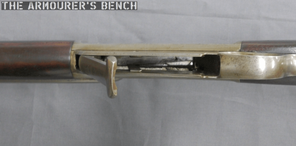
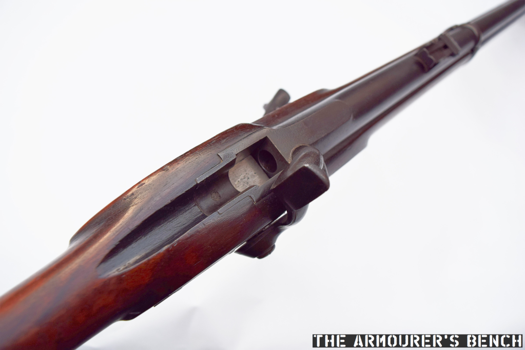
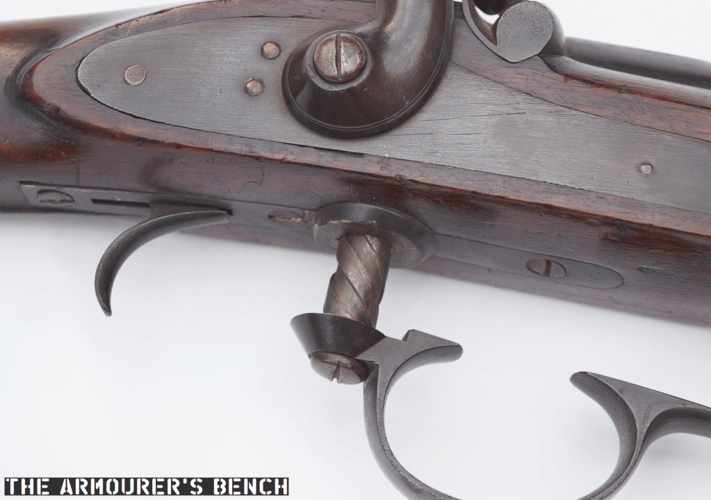
Like the earlier Ferguson rifle, which drew heavily on earlier screw breech designs, this rifle has a rotating trigger guard which acts as a lever to unscrew the breech. Rotating the trigger guard drops a rectangular breechblock and opens the action. Unlike the Ferguson the threaded piece does not act as the breech plug itself, instead the separate breech block takes the brunt of the cartridge ignition.

The rifle with its breech open (Matthew Moss)

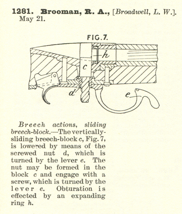
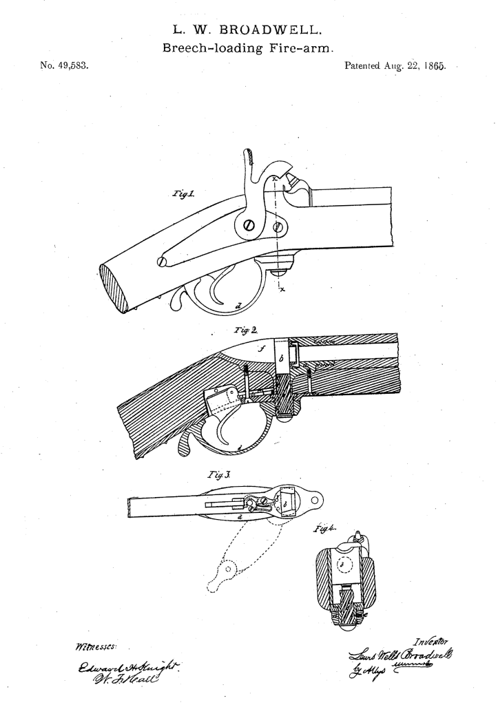
Broadwell filed the patent believed to correspond to this rifle first in Britain, in May 1863, and subsequently in the US in August 1865 (US #49583). The patent protected the breech action and depicts what Broadwell described as a ‘screwed nut’ below a rectangular vertically sliding breech block. This idea of a sliding breech-block builds on his earlier patent for a sliding cannon breech.

Broadwell’s UK patent, dated 1863 (UK Patent courtesy of Research Press)

In Britain, Broadwell used Richard Brooman, of Robertson, Brooman and Company, as a patent agent. At the time Brooman’s company offered a service by which he acted as the inventor’s deputy and was listed as the patent holder, while the inventor was listed as the ‘communicator’. The service cost the not insignificant sum of £45 (at the time a labourer could earn just 3 shillings 9 pence per week – or 15% of £1 – that’s just under a year’s average wages). This initial sum covered the patent for three years. It is likely Broadwell employed an agent because at the time he was living in St Petersburg in Russia, undertaking negotiations with the Russian Government to establish Gatling Gun production. Brooman was also the editor of The Mechanics’ Magazine, a Victorian science and industry journal.

Broadwell’s slightly different 1865 US patent which is also similar to the rifle we are examining (US Patent Office)

The breech plug has a screw thread with a very wide pitch with flat crests. Broadwell’s US patent describes the breech plug as having a ‘three to six threaded screw’. The breech blog falls enough to allow loading after turning the lever around 200-degrees – ensuring a rapid action. Interestingly the British patent shows the lever not attached to the base of the screw plug but instead shows it at the mid-point of the screw. This may be an error in the drawing. It seems that if the rifle we are examining is a Broadwell prototype it was decided to simplify the action by attaching the lever at the base of the plug.

A close up of the rifle’s trigger guard and screw (Matthew Moss)

This rifle itself, has no markings whatsoever, not even range markings on the rear sight. Typically rifles of this period would at least have a marker’s or patent holder’s mark on the barrel or lock plate. This suggests that the rifle is either unfinished or more likely a prototype which did not require extensive markings.

The rifle’s unmarked rear sight (Matthew Moss)

The breechblock is not blued and is possibly case hardened. Much like the Ferguson, and other earlier screw-breech rifles the trigger guard also acts as the breech lever. Which with a rotation of approximately 200 degrees, descends enough to open the breech and allow access to the chamber. The threaded screw is around 0.5 in (1.2cm) thick and acts on a rectangular breechblock which sits above it. This basic layout matches Broadwell’s 1863 UK patent.

The rifle with its breech partially closes, there is no method of extraction indicating it used a combustible cartridge (Matthew Moss)

The rectangular shape of the breechblock ensures a strong action as it butts up against a pair of narrow shoulders (about 1mm in width) at the rear of the receiver. The rifle has a two band stock and a cleaning/ramrod which indicates a military-style rifle but interestingly, there is no obvious provision for fixing a bayonet.

The rifle is believed to be chambered in a cartridge using a .451 Westley Richards projectile. There is no method for extraction so we can safely assume the rifle used a combustible cartridge, ignited by a percussion cap rather than a self-contained metallic cartridge. Interestingly, the UK patent also suggests the use of a “tubular magazine… formed in the hammer, containing self-acting feeding apparatus for supplying ignition wafers or patches to the nipple.” This is not mentioned in the later US patent and the rifle we’re examining has a conventional capped percussion lock.

A close up of the Note rectangular breech with the action closed (Matthew Moss)

The US patent describes a ‘mechanism to prevent the gun from being fired when the breech is open’, this is formed by a lever which disengages with the trigger when the breech lever is rotated. There is a small leather flange in the base of the stock where the screw ascends and descends, this prevents the ingress of dirt and also acts to keep the screw clean.

Left profile of the rifle (Matthew Moss)

Compared to Patrick Ferguson’s action Broadwell’s design simplifies the breech plug using a simpler to manufacture rectangular breechblock and a thinner screw plug. The use of a self-contained cartridge would have sped up loading but the need to cap the rifle’s nipple was still a limiting factor. The screw breech concept became increasingly obsolete with the introduction of self-contained metallic cartridges with integral primers as well as the introduction of faster actions including bolt actions, falling block actions and toggle-locked lever actions.

Lewis Broadwell was born in Cincinnati, Ohio, on 18th July 1820. He is perhaps best known for his drum magazine design for the Gatling Gun. The Broadwell Drum consisted of a series of single stack, gravity assisted magazine columns arrayed around a central pivot point. These columns held between 15 and 20 rounds depending on calibre and typically there were 16 columns of ammunition. Broadwell patented the drum’s design in December 1870. It was used extensively during the 1870s by a number of militaries around the world, including by the British Army. Broadwell was granted his last patent in 1876 and died, aged 86, in May 1906.

Special thanks to the Hayes collection for letting us take a look at this very interesting rifle. Thanks to David over at the Research Press for help finding the patent and to John Walter for his help finding information on Broadwell himself.


If you enjoyed the video and this article please consider supporting our work here. We have some great perks available for Patreon Supporters. You can also support us via one-time donations here.