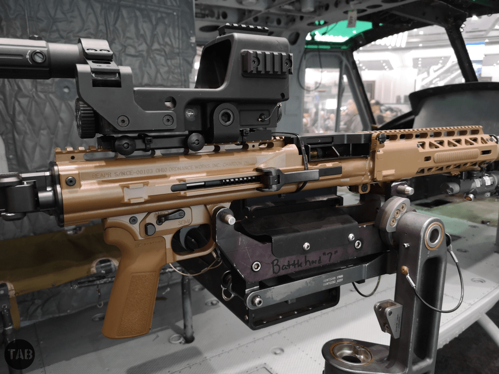
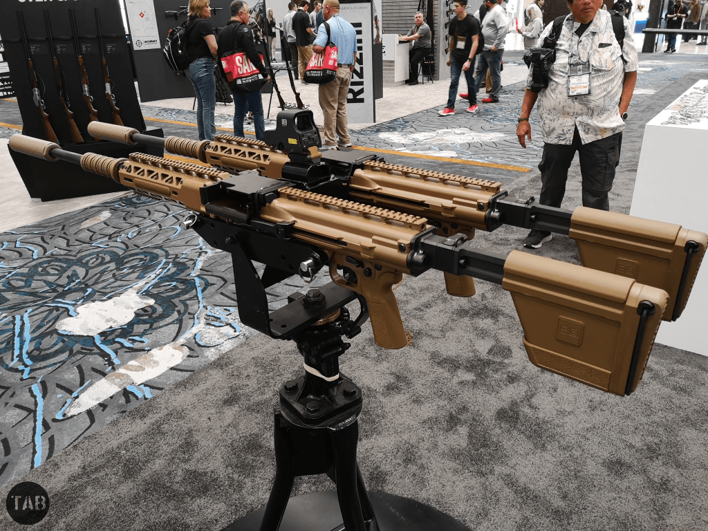
At SHOT Show in 2022, Ohio Ordnance Works teased their new .338 light weight medium machine gun, keeping the gun’s key features hidden under strategically placed scrim. This year the REAPR was unveiled for all to see. The REAPR or Recoil Enhanced Automatic Rifle is chambered in .338 Norma Magnum and can also be calibre converted to 7.62x51mm.
The gun was developed by Ohio Ordnance Works (OOW) in response to solicitations from the US SOCOM and US Marine Corps for a Lightweight Medium Machine Gun in .338NM. The niche requirement for a .338 gun dates back to at least 2012 with the first Sources Sought Solicitation being launched in May 2017. The solicitation requested:
“The LWMMG should fire the belted .338NM round of ammunition with a polymer case. The LWMMG should weigh less than 24 pounds unloaded with a barrel length of 24in. The LWMMG should have a rate of fire of between 500-600 rounds per minute. Weapon shall be compatible with current rail mounted aiming systems with the ability to incorporate more advanced fire control technology. The system should include both a suppressed barrel and an unsuppressed barrel that can be rapidly changed. The LWMMG should include a tripod that is lightweight and provides the stability and accuracy required to engage targets at extreme ranges. The LWMMG should be able to mount in current machine gun mounts designed for the M240B/C. The weapon should have sufficient accuracy to engage area targets and vehicles at 2,000m.“
General Dynamics led the field developing their .338 machine gun but this design was later divested to True Velocity and since then SIG Sauer have also developed their MG338/SL MAG. The 2017 solicitation is now inactive, however, in 2021 SOCOM (via PEO SOF Warrior, PM Lethality) began seeking an ‘LMG-M’. LMG-M project seeks a gun that can engage targets out to 2,500m and has a similar weight and form factor to an M240B. A contract had been hoped to be awarded by the end of 2022, however, this slipped back to 2025 and now likely 2026.
The aim of .338 machine guns is to fill the gap between the 7.62mm GPMG and the .50 HMG while providing a dismounted, lighter weight platform that can give the performance of a .50 calibre machine gun.
OOW began work on their gun in 2020 with numerous patents granted on its features. The REAPR is a select-fire weapon with ambidextrous controls on either side of the pistol grip assembly as well as a traditional cross-bolt safety. The pistol grip itself can be swapped out for any AR-15/M16 compatible grip. Robert W. Landies, OOW’s president and one of the designers of the gun, told me that with REAPR they addressed a lot of the pet peeves they had with legacy machine guns designs and that they “took a lot of features and amalgamated the best of them” when designing the weapon. Intriguingly, the gun uses a roller delayed operating system, similar to that of the MG45, this means the opening of the action is slowed by rollers but does not fully lock. Post-Second World War Two this system had some influence on a range of designs including the SIG MG 710-3 and a host of Heckler & Koch weapons. The gun uses a pair of springs on dual guide rods and has a 600 rpm rate of fire. The weapon can be field stripped without tools. To remove the action a pin at the rear is removed which allows the butt stock and rear of the receiver to be removed with the springs, guide rods and bolt sliding out of the receiver.
It has a side folding stock, designed in house with B5, with a shoulder rest and an adjustable cheek riser. B5 also provided the REAPR’s P23 Grip and MLOK rail covers. According to OOW the REAPR weighs in a 26.8lbs and has an overall length of 51.7in (131cm) when the stock is collapsed, 54.5in (138cm) when deployed and 44in (112cm) when folded (it can fold either to the left or right). For use when mounted on vehicles or aircraft the stock can be removed and a spade grip kit can be fitted. There is also a rail mounted removeable carrying handle.
A key feature is the gun’s barrel quick change system, this can be done with one hand by the operator. The change can also be done with the bolt either in the forward or rear position. The patented system uses 2 opposing groups of 5 interrupted threads, this allows the barrel to be released with just a 90-degree turn. To remove the barrel the operator grasps the barrel cover, pushes the barrel rearward, towards the receiver, and then turns the barrel 90-degrees to disengage it. The REAPR can be mounted with a suppressor, it has been seen paired with cans from a number of different manufacturers.
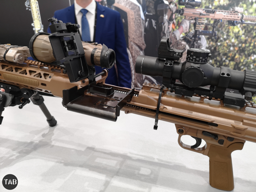
Another feature is that the entire system can be broken down into 3 pieces within 10-20 seconds. It can be packed away with the barrel at 24.5in (61cm) being the longest component. The REAPR has a one-piece steel receiver and an aluminium hand guard with MLOK slots, which can be removed via a pair of catches. The gun also has MIL-standard mounting points for either tripod or pintle mounting. Another key, patented, feature is the gun’s feed tray which can slide out to the side of the gun for loading and clearing, this allows the operator to use optics with a larger continuous footprint. SIG Sauer addressed this issue by having a cover which hinges to the side. The REAPR’s direction of feed can be flipped either left or right and ejection is through the bottom of the receiver. OOW note that the gun has a mounting interface for an ammunition pouch on the left side of the receiver but are considering adding one to the right side but are waiting on feedback from users.
OOW say that the REAPR is currently available for ordering in test quantities but full volume production is set to begin in April 2024. The REAPR seems to be a very competent, well thought out design with a lot of promise. It will be interesting to see how the LMG-M programme progresses.
Support Us: If you enjoyed this video and article please consider supporting our work here. We have some great perks available for Patreon Supporters – including early access to custom stickers and early access to videos! Thank you for your support!
Bibliography:
‘Firearm top cover with multiple degrees of freedom of motion’, US Patent #11268774B1, (source)
‘Quick-change barrel for a firearm’, US Patent #11598600B2, (source)
By 1895 Winchester had been considering a slide-action rifle for some time, in 1882 William Mason had begun work on one (US Patent #278987) to counter Colt’s slide-action Lightning only to drop it. Finally in 1890, Winchester introduced a slide-action .22 calibre rifle developed by John Browning. The Model 1890 became extremely popular.
Between 1887 and 1895 Browning patented four slide-action rifle designs. The first of these, US patent #367336, was granted in July 1887, this was followed in 1888 by US patent #385238. In September 1890, the Browning brothers were granted US patent #436965, which along with the previous 1888 patent protected what became the Model 1890. Three years later Winchester introduced the Model 1893 pump action shotgun, that would eventually evolve into the famous Winchester Model 1897.
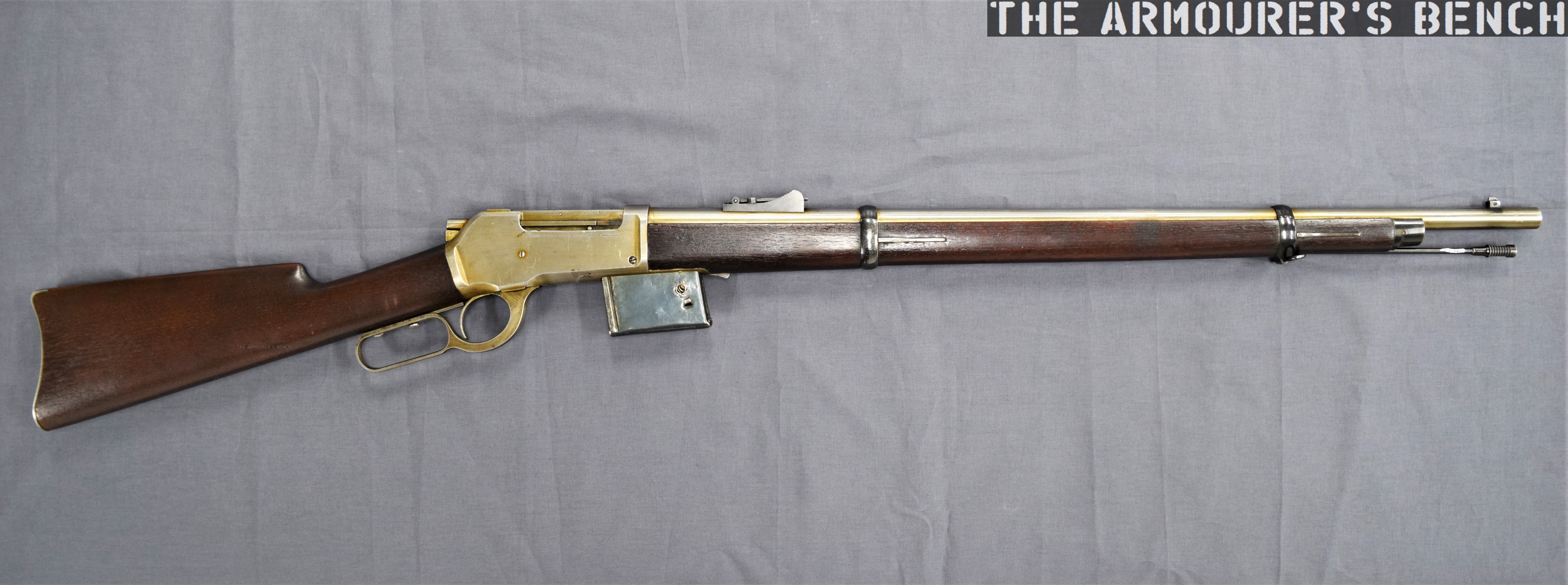
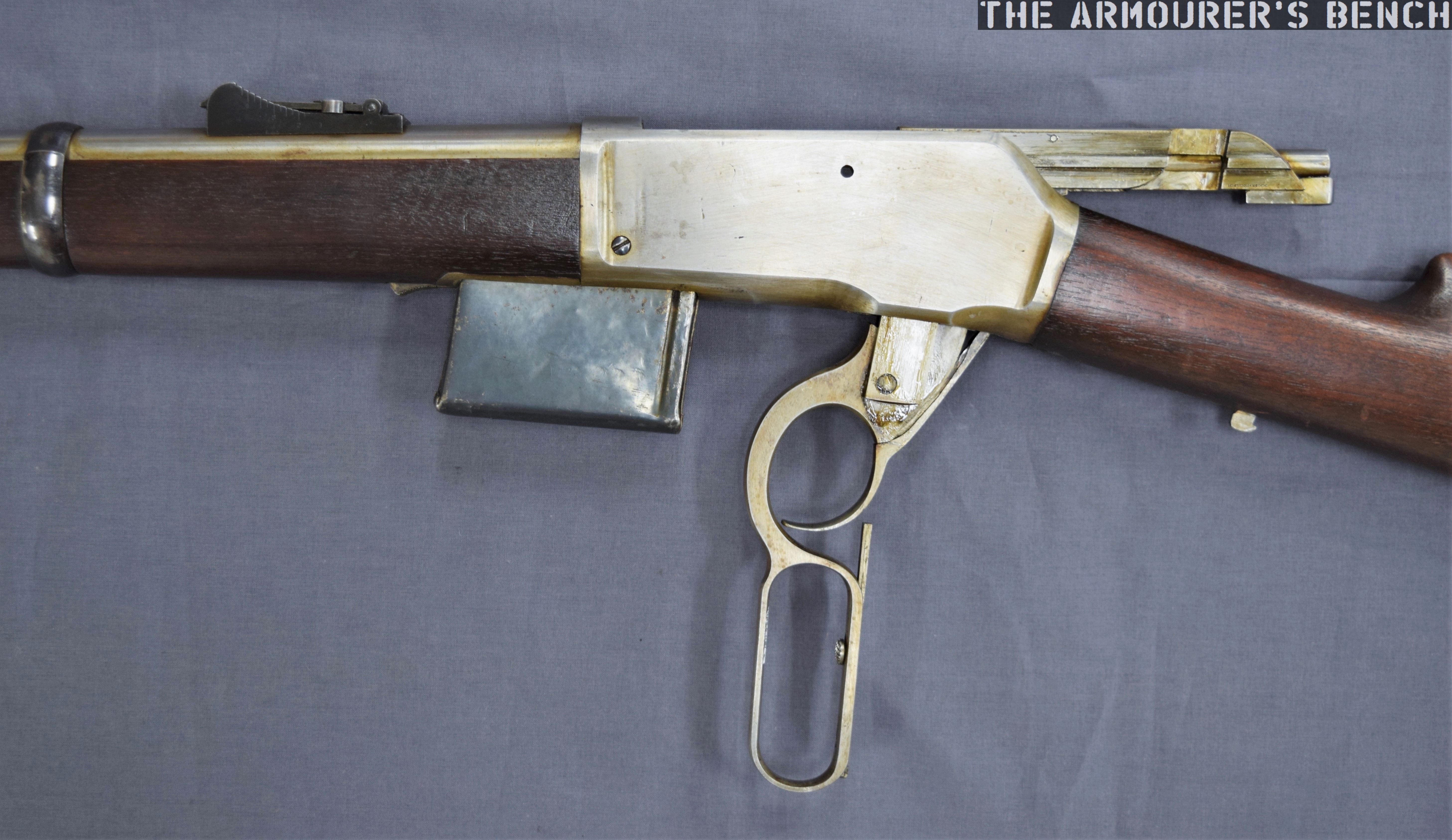
Right-side close up of the rifle with its action open (Matthew Moss)
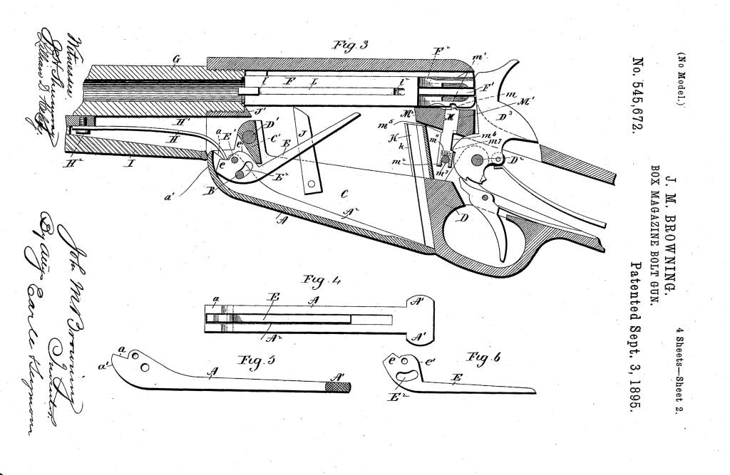
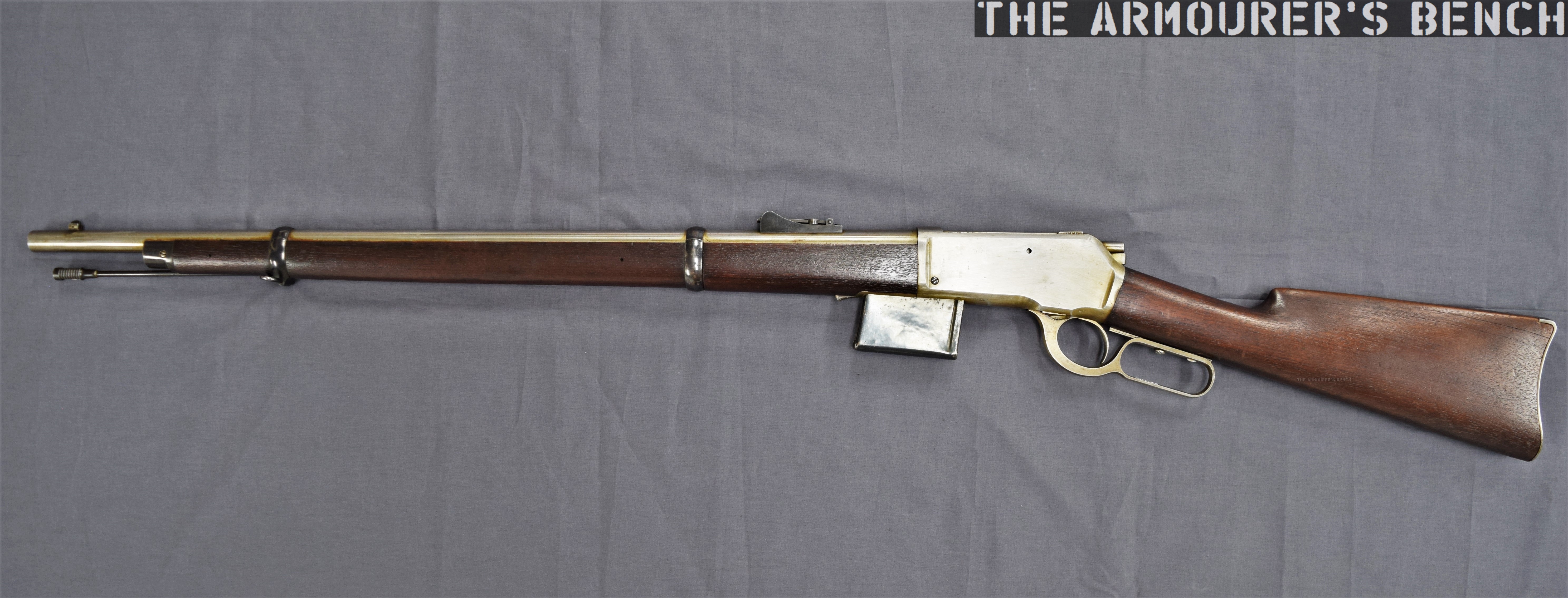
Finally, April 1895, Browning filed a patent for a design for a .30 calibre rifle which was granted in September 1895 (US patent #545672) This patent covers the rifle we’re examining here. The rifle itself is a slide or pump action in long barrelled configuration which Winchester described as a ‘Musket’.
The September 1895 slide-action design was purchased by Winchester but like so many other Browning designs, it never entered production and Winchester purchased the design purely to secure it and prevent other rival manufacturers picking it up. Winchester instead went with a lever-action design, patented in November 1895 (US #549345), which became the famous Winchester Model 1895.
A left-side view of the rifle’s receiver with Browning’s patent overlaid (Matthew Moss)
The September 1895 slide or pump-action rifle design had a laterally camming locking breechblock. As we can see, externally Browning’s toolroom prototype looks somewhat similar to the contemporary Winchester Model 1895, with a single-stack integrated box magazine but with a pump sleeve rather than a lever.
An action-bar connects the slide/pump to the front of the breechblock/bolt carrieron the right-hand side of the rifle. The slide handle itself is made of a U-shaped piece of metal which wraps around the rifle’s forend. The slide has been roughly cross hatched to improve grip. There is a channel cut into the furniture for the action arm’s attachment point to travel. The slide is attached to the arm by a pair of screws.
A close up of the rifle’s slide/pump handle (Matthew Moss)
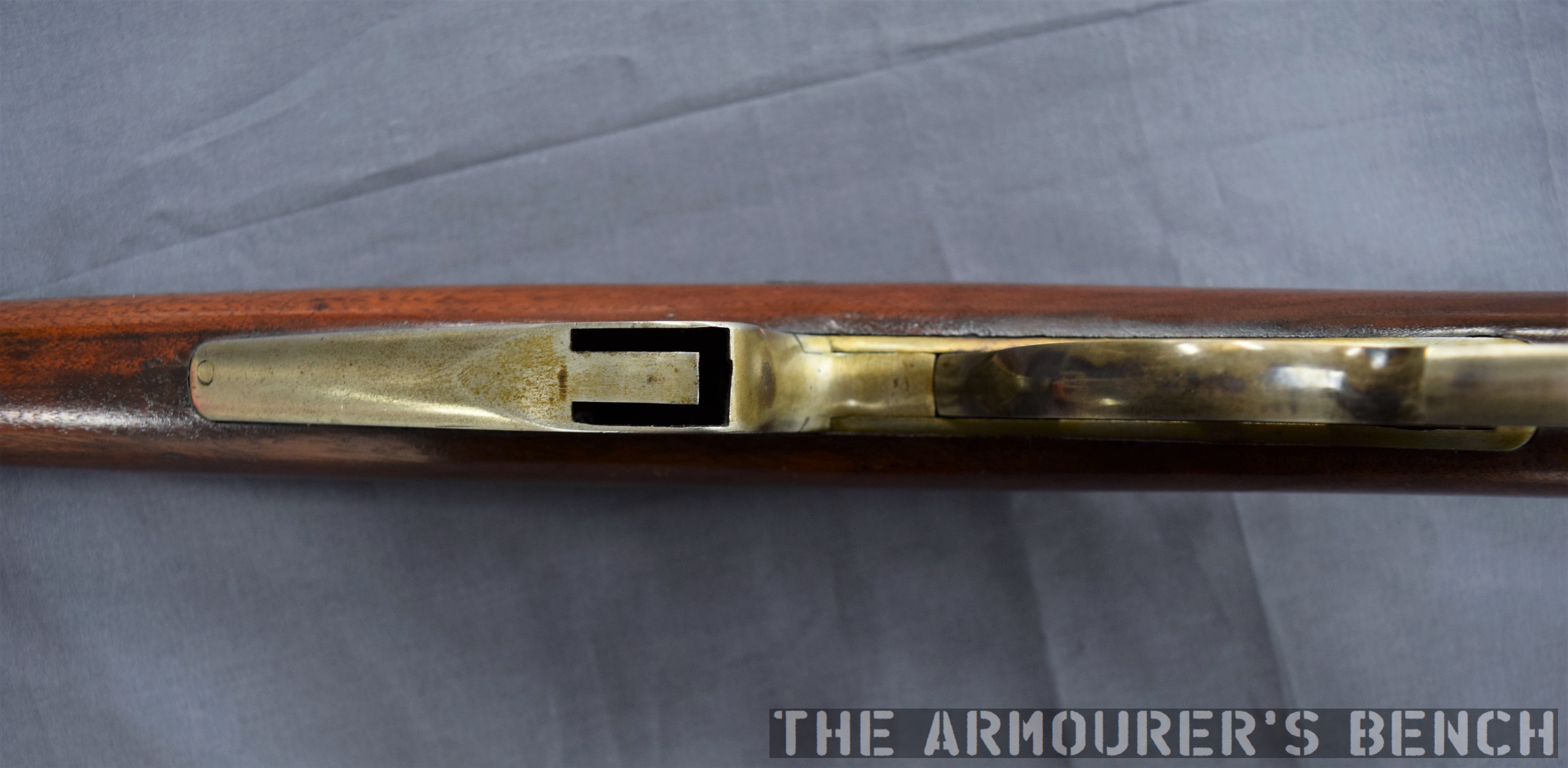
However, Browning developed this prototype to allow loading of the magazine from below rather than through the top of the receiver. He added a hinged floor plate, with a spring loaded follower, that allowed loose rounds to be dropped into the magazine and then closed.
As we open the magazine, hinging the cover plate down, we see the carrier flip down against the plate to allow loading. The rifle was designed to be loaded from below with the bolt forward.
Browning’s September 1895 patent (US Patent Office)
In the patent description Browning explained that his aim was to improve breech-loading box-magazine firearms by designing:
“…a simple, compact, strong, highly effective, and safe gun, containing comparatively few parts and constructed with particular reference to provision for charging the box-magazine with cartridges from the bottom of the frame of the arm while the breech-bolt is in its closed position, so that the arm may be charged without operating its action mechanism or disturbing the cartridge in the gun-barrel, if one is there.”
Browning’s September 1895 patent (US Patent Office)
From the original patent drawings we can see the flat spring which acted on the carrier running below the barrel, ahead of the magazine. Inside the magazine are a pair of what Browning refers to as ‘spring fingers’ these act on the cartridges inside the magazine and keep them properly aligned, seen here in Fig.7 of the patent. In Fig.8 we can see what Browning calls a ‘box-like guideway’ which guide the rims of the cartridges, “preventing the cartridges from being displaced while being fed upwards.”
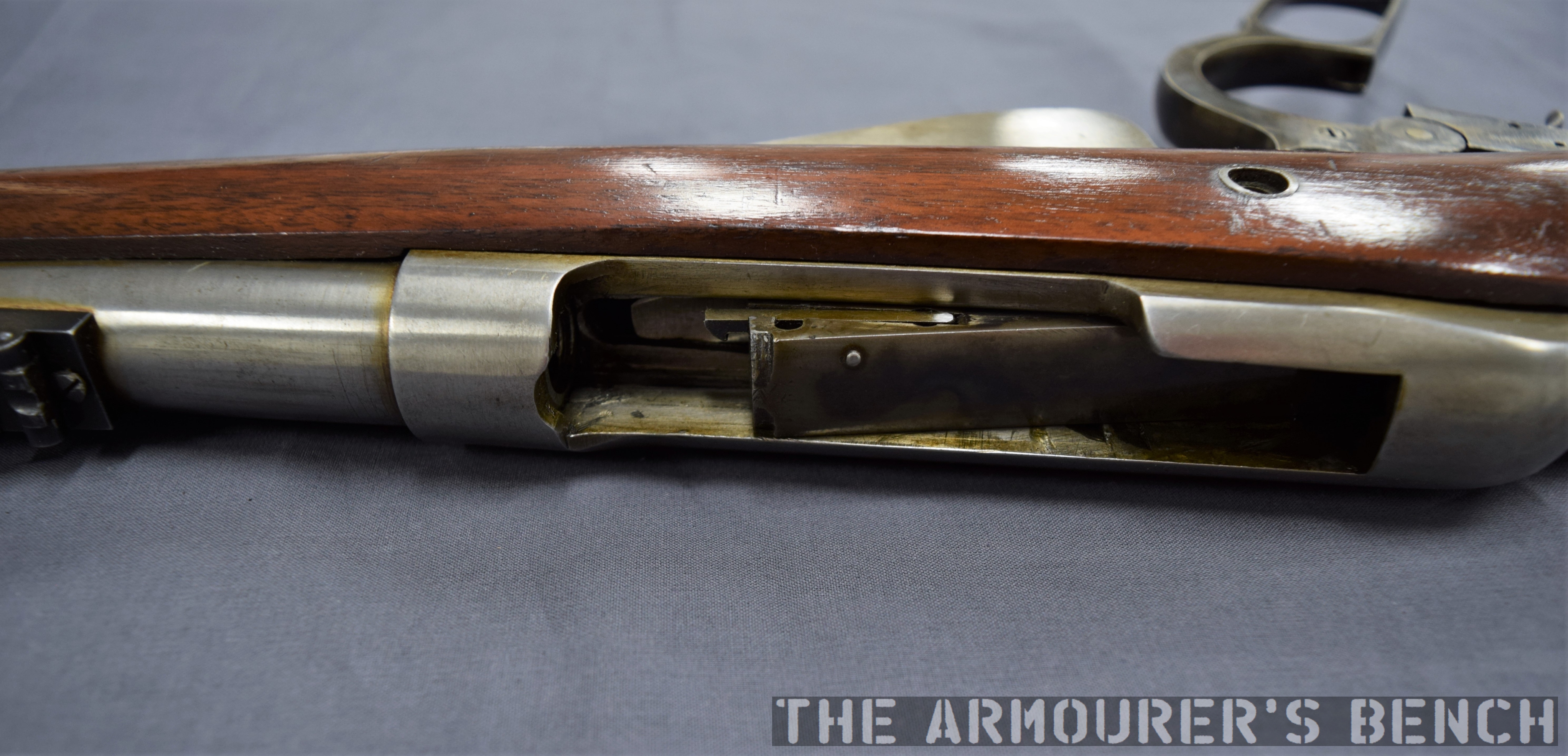
The rifle’s breechblock locked into a recess in the left side of the receiver, tilting at an angle with the rear of the breechblock canting to the left. When the pump handle was pulled rearwards the breechblock cammed laterally to unlock the action, extracted and ejected any spent casing and when the slide/pump was returned forward a new cartridge was picked up from the magazine, chambered the breechblock locked again ready to fire. The rifle’s hammer was cocked by the rearward movement of the breechblock.
A left-side view of the rifle with its action open, note the complex machining on the rear of the breech bolt (Matthew Moss)
Externally, the slide-action’s receiver looks similar to that of the production Model 1895 but internally they are very different. The action is certainly less open than the Model 1895’s but the lateral locking mechanism is less robust. Additionally, with no lever, as in the Model 1895, the slide-action rifle lacks the safety mechanism which prevents the action from opening accidentally.
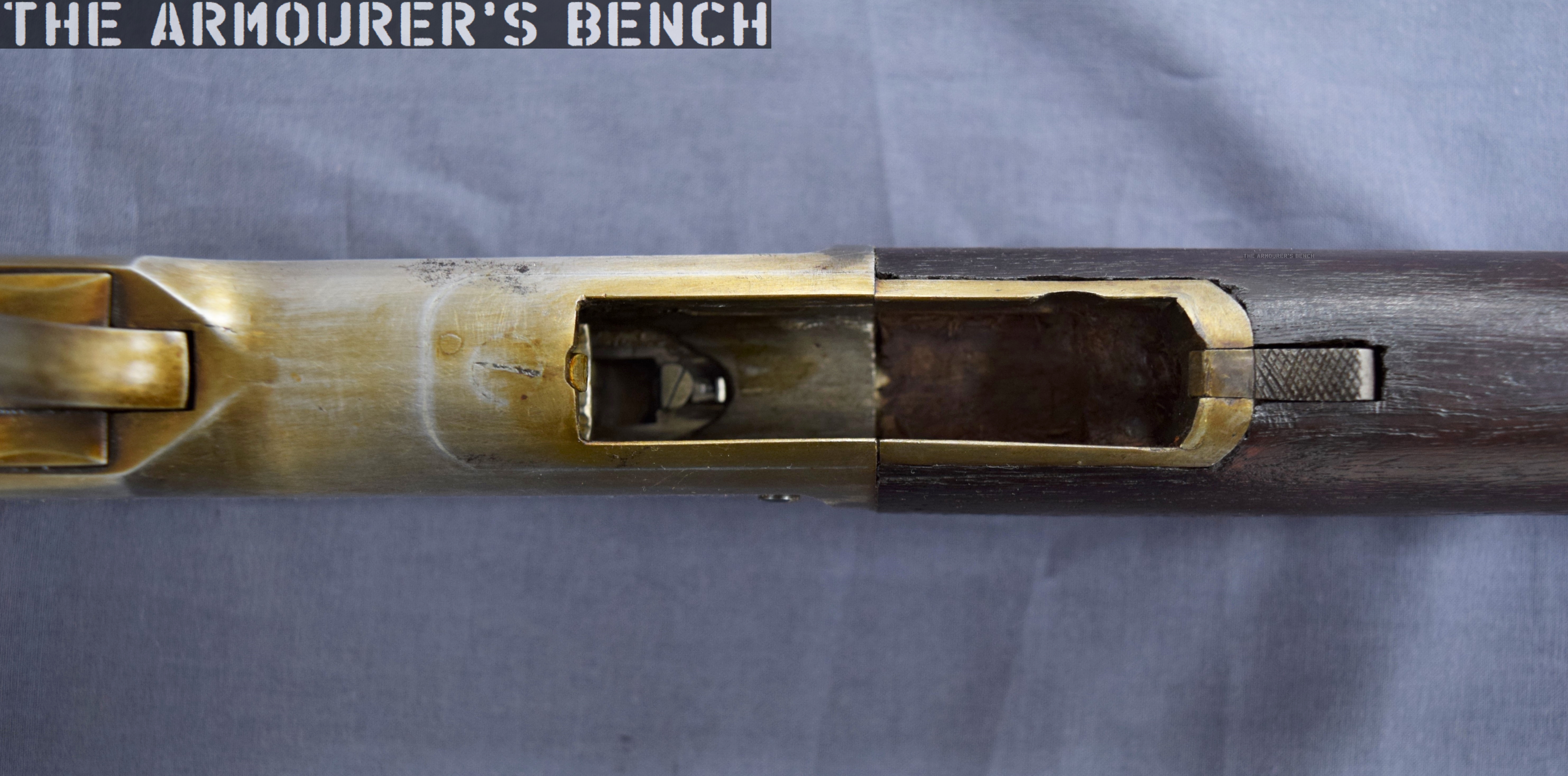
A view inside the open magazine with the floorplate hinged open (Matthew Moss)
The model is in the white and while externally the machining and tool work is very neat, inside the action we can see where the cuts in the receiver wall have been more crudely made. In terms of design, the slide-action prototype was certainly simpler and had fewer working parts than the Model 1895 lever-action.
Winchester purchased the .30 calibre slide-action design but never produced it, it is believed that only Browning’s prototype was built to prove the concept. The prototype was part of Winchester’s collection and may now be found at the Cody Firearms Museum.
In this video and article we’ll examine a somewhat mysterious screw breech percussion rifle – if you, like me ever wondered what a Ferguson with a percussion lock might look like then you’ll find this one fascinating. If you haven’t seen our earlier video on Patrick Ferguson’s 18th century breechloading rifle, check that out!
Right profile of the rifle (Matthew Moss)
This rifle likely dates to the mid-1860s and from some research is believed to be based on a design patented by Lewis Wells Broadwell, an American inventor. Broadwell was granted his first patent in 1861, protecting a sliding breech design for artillery. During the 1860s & 70s Broadwell was employed as the European Sales Agent for the Gatling Gun Company. He held a number of firearms and ordnance related patents, granted between 1861 and 1876. With several relating to artillery carriages, ammunition and magazine systems. His screw breech (US #33876) and a gas check (US #167981) designs for artillery were used by Krupp in some of their guns including the popular 68mm breechloading Mountain Gun.
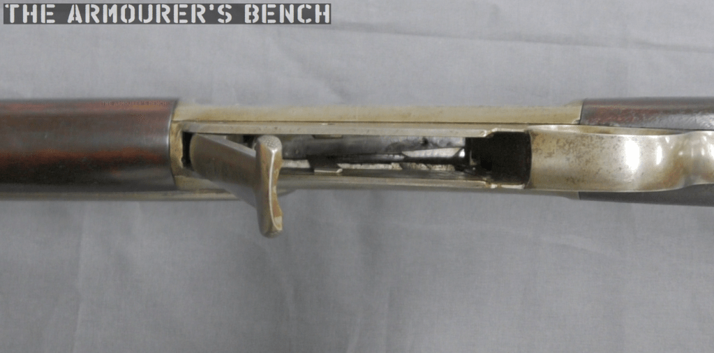
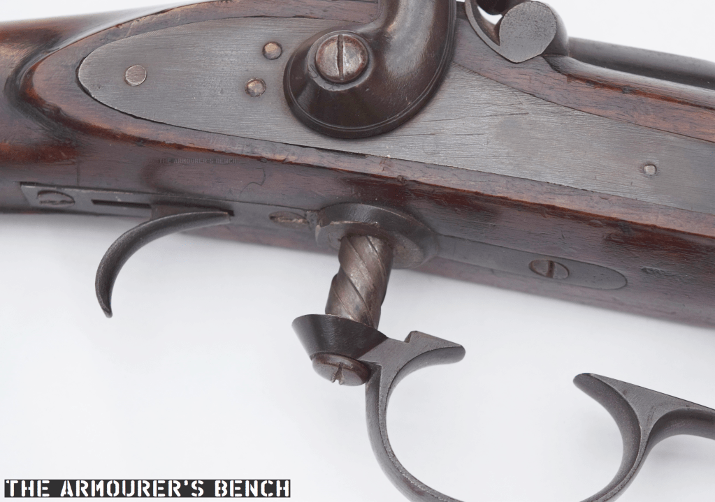
The rifle with its trigger guard rotated forward and its breech open (Matthew Moss)
Like the earlier Ferguson rifle, which drew heavily on earlier screw breech designs, this rifle has a rotating trigger guard which acts as a lever to unscrew the breech. Rotating the trigger guard drops a rectangular breechblock and opens the action. Unlike the Ferguson the threaded piece does not act as the breech plug itself, instead the separate breech block takes the brunt of the cartridge ignition.
The rifle with its breech open (Matthew Moss)
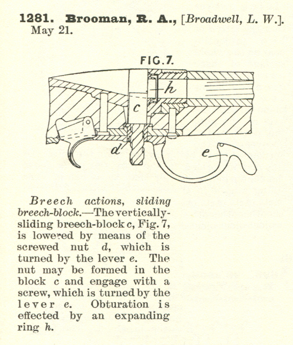
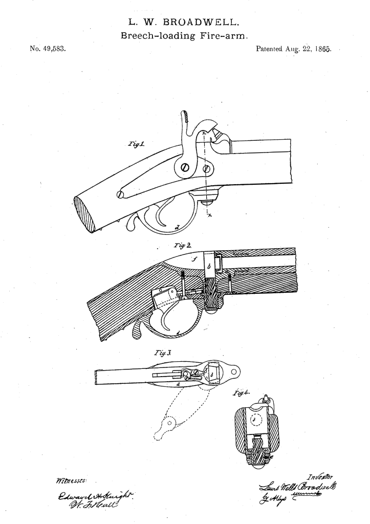
Broadwell filed the patent believed to correspond to this rifle first in Britain, in May 1863, and subsequently in the US in August 1865 (US #49583). The patent protected the breech action and depicts what Broadwell described as a ‘screwed nut’ below a rectangular vertically sliding breech block. This idea of a sliding breech-block builds on his earlier patent for a sliding cannon breech.
Broadwell’s UK patent, dated 1863 (UK Patent courtesy of Research Press)
In Britain, Broadwell used Richard Brooman, of Robertson, Brooman and Company, as a patent agent. At the time Brooman’s company offered a service by which he acted as the inventor’s deputy and was listed as the patent holder, while the inventor was listed as the ‘communicator’. The service cost the not insignificant sum of £45 (at the time a labourer could earn just 3 shillings 9 pence per week – or 15% of £1 – that’s just under a year’s average wages). This initial sum covered the patent for three years. It is likely Broadwell employed an agent because at the time he was living in St Petersburg in Russia, undertaking negotiations with the Russian Government to establish Gatling Gun production. Brooman was also the editor of The Mechanics’ Magazine, a Victorian science and industry journal.
Broadwell’s slightly different 1865 US patent which is also similar to the rifle we are examining (US Patent Office)
The breech plug has a screw thread with a very wide pitch with flat crests. Broadwell’s US patent describes the breech plug as having a ‘three to six threaded screw’. The breech blog falls enough to allow loading after turning the lever around 200-degrees – ensuring a rapid action. Interestingly the British patent shows the lever not attached to the base of the screw plug but instead shows it at the mid-point of the screw. This may be an error in the drawing. It seems that if the rifle we are examining is a Broadwell prototype it was decided to simplify the action by attaching the lever at the base of the plug.
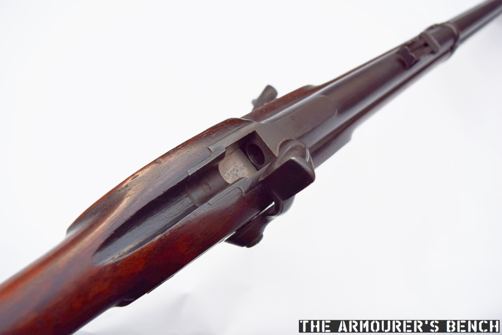
A close up of the rifle’s trigger guard and screw (Matthew Moss)
This rifle itself, has no markings whatsoever, not even range markings on the rear sight. Typically rifles of this period would at least have a marker’s or patent holder’s mark on the barrel or lock plate. This suggests that the rifle is either unfinished or more likely a prototype which did not require extensive markings.
The rifle’s unmarked rear sight (Matthew Moss)
The breechblock is not blued and is possibly case hardened. Much like the Ferguson, and other earlier screw-breech rifles the trigger guard also acts as the breech lever. Which with a rotation of approximately 200 degrees, descends enough to open the breech and allow access to the chamber. The threaded screw is around 0.5 in (1.2cm) thick and acts on a rectangular breechblock which sits above it. This basic layout matches Broadwell’s 1863 UK patent.
The rifle with its breech partially closes, there is no method of extraction indicating it used a combustible cartridge (Matthew Moss)
The rectangular shape of the breechblock ensures a strong action as it butts up against a pair of narrow shoulders (about 1mm in width) at the rear of the receiver. The rifle has a two band stock and a cleaning/ramrod which indicates a military-style rifle but interestingly, there is no obvious provision for fixing a bayonet.
The rifle is believed to be chambered in a cartridge using a .451 Westley Richards projectile. There is no method for extraction so we can safely assume the rifle used a combustible cartridge, ignited by a percussion cap rather than a self-contained metallic cartridge. Interestingly, the UK patent also suggests the use of a “tubular magazine… formed in the hammer, containing self-acting feeding apparatus for supplying ignition wafers or patches to the nipple.” This is not mentioned in the later US patent and the rifle we’re examining has a conventional capped percussion lock.
A close up of the Note rectangular breech with the action closed (Matthew Moss)
The US patent describes a ‘mechanism to prevent the gun from being fired when the breech is open’, this is formed by a lever which disengages with the trigger when the breech lever is rotated. There is a small leather flange in the base of the stock where the screw ascends and descends, this prevents the ingress of dirt and also acts to keep the screw clean.
Left profile of the rifle (Matthew Moss)
Compared to Patrick Ferguson’s action Broadwell’s design simplifies the breech plug using a simpler to manufacture rectangular breechblock and a thinner screw plug. The use of a self-contained cartridge would have sped up loading but the need to cap the rifle’s nipple was still a limiting factor. The screw breech concept became increasingly obsolete with the introduction of self-contained metallic cartridges with integral primers as well as the introduction of faster actions including bolt actions, falling block actions and toggle-locked lever actions.
Lewis Broadwell was born in Cincinnati, Ohio, on 18th July 1820. He is perhaps best known for his drum magazine design for the Gatling Gun. The Broadwell Drum consisted of a series of single stack, gravity assisted magazine columns arrayed around a central pivot point. These columns held between 15 and 20 rounds depending on calibre and typically there were 16 columns of ammunition. Broadwell patented the drum’s design in December 1870. It was used extensively during the 1870s by a number of militaries around the world, including by the British Army. Broadwell was granted his last patent in 1876 and died, aged 86, in May 1906.
Special thanks to the Hayes collection for letting us take a look at this very interesting rifle. Thanks to David over at the Research Press for help finding the patent and to John Walter for his help finding information on Broadwell himself.
The Cody Firearms Museum, at the Buffalo Bill Centre of the West, holds a number of interesting select-fire M1 Garand rifles, adapted by Winchester during the 1940s. In this article we’re going to examine one of the prototypes, the rifle is believed to date to the late 1940s, and appears to be chambered in one of the earlier iterations of the T65 .30 Light Rifle round, which would eventually be adopted as 7.62x51mm.
Very little information is available about the rifle and little has been written about it previously. It is believed to have been developed by Winchester engineer Harry H. Sefried II with former Cody Firearms Museum curator Herbert Houze crediting Sefried with the rifle, which he described as adaptation of the M1 into a ‘squad automatic rifle’. After some archival research and combing Winchester’s patents from the period we can now attempt to shed light on a little more of the rifle’s history.
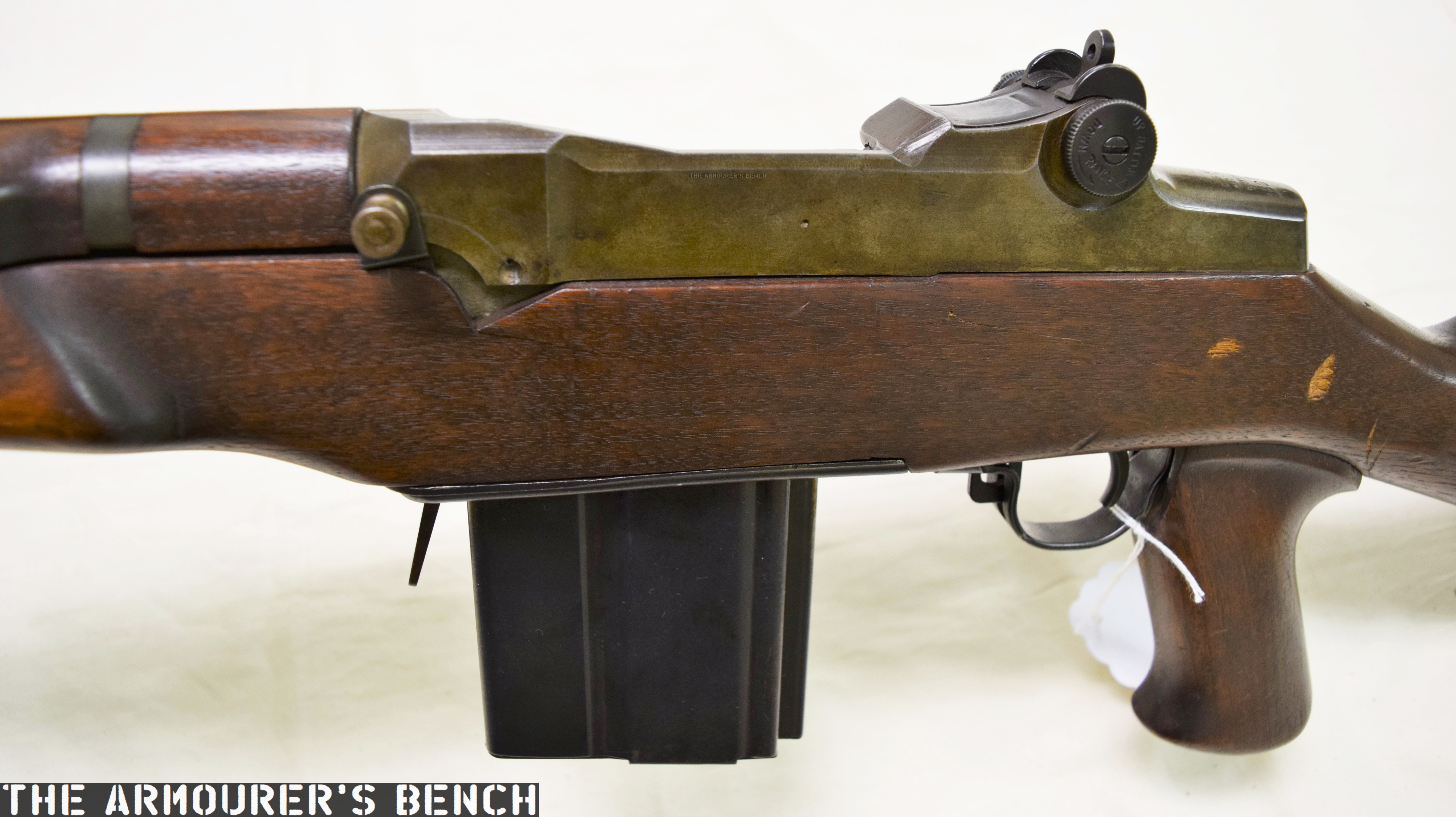
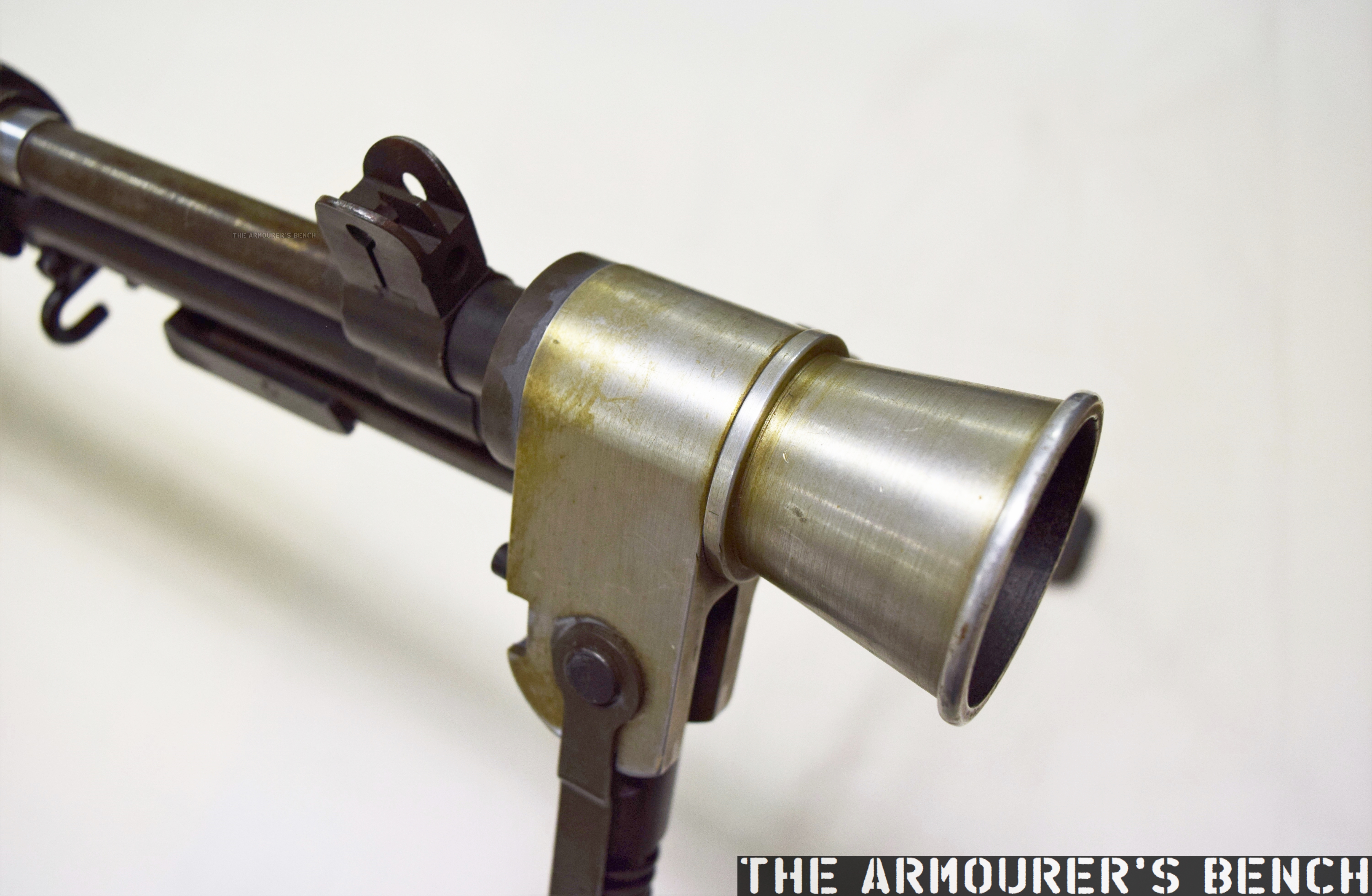
Externally, the rifle has a number of instantly recognisable distinctions from the standard M1 Garand. It has a reshaped stock with an added pistol grip, a proprietary box magazine and a combined bipod and conical flash hider. If we look closer we’ll notice that the stock has a swell just ahead of the breech, flaring out in an almost triangular bulge. These changes to the stock also distinguish this rifle from Winchester’s other select-fire M1 adaptations, which retain the standard Garand stock profile.
From the patents available combined with an examination of the rifle we can learn a lot. We cannot rely on patents to tell the whole story of the rifle, however, as many of the elements that make up the weapon appear to have gone unpatented. The substantial external and internal changes made to the rifle suggest that this was not an attempt to adapt the M1 with a minimal number of component parts changes but rather an effort to generally improve the rifle, making it conducive to fully automatic fire.
Detail photo showing the rifle’s pistol grip, altered stock and magazine (Matthew Moss)
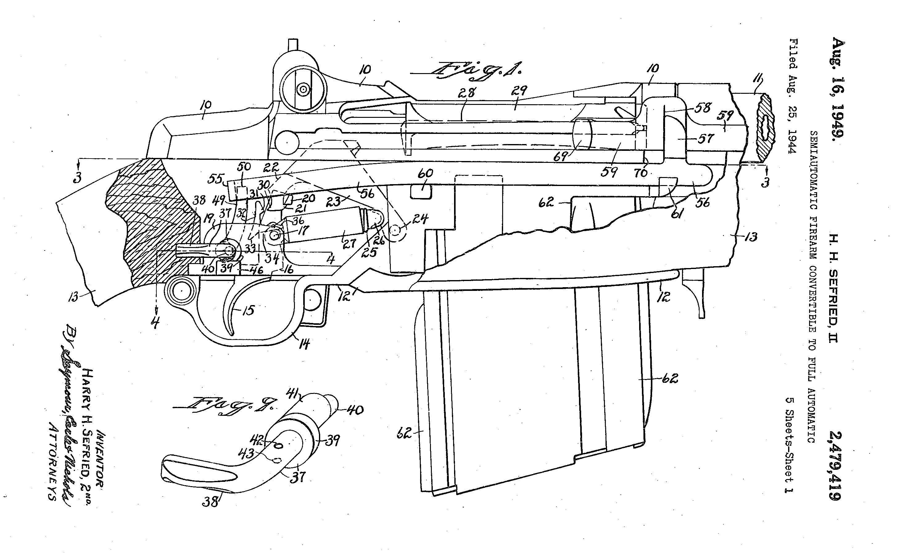
In summer 1944, Winchester’s CEO Edwin Pugsley directed Sefried to begin work on a select-fire conversion for the M1, to rival those being developed at Springfield Armory and Remington. Winchester’s select-fire Garand went though a number of iterations which resulted in two patents from Sefried. The first, filed in August 1944 (US #2479419), incorporated an elongated sear actuating lever and a selector on the lower, right side of the receiver. Winchester’s first attempts at a select-fire M1 conversion resulted in rifles with extremely high, uncontrollable rates of fire of over 900 rounds per minute. Sefried filed a second patent later in January 1948 (US #2464418) which used a catch to hook the sear. The rifle we are examining appears to have yet another select-fire system, one for which I have so far been unable to find a corresponding patent for. Winchester’s work on the select-fire adaptation came to a halt with the end of the war. It appears, however, that Winchester again began to work on adapting the M1 in the late 1940s, with Sefried again working on the project, filing his second select-fire mechanism patent in 1948 (US #2464418).
Sefried’s 1949 patent for another select-fire M1 conversion (US Patent Office)
The rifle’s receiver was originally a standard Winchester-made .30-06 M1 with a serial number of 1,627,456. This means its wartime production gun, dating from May 1945. It would appear that rather than the rifle being lifted from the rack finished, it seems that it was earmarked for prototype development because the receiver forging lacks the cuts/forgings needed for the en bloc clip release lever. This makes sense if it was known that the receiver was destined for use in a prototype which fed from a box magazine. However, the timeline of the rifle gets more complex when we consider that it was a late-war production rifle. There are a number of possibilities. The rifle may have been simply set aside for internal prototype work in May 1945 and not used until a T65 chambered rifle was developed later. Alternatively, it is possible that the rifle was converted during the initial attempts to create a select-fire M1 but was later rechambered from .30-06 to the new developmental T65 round.
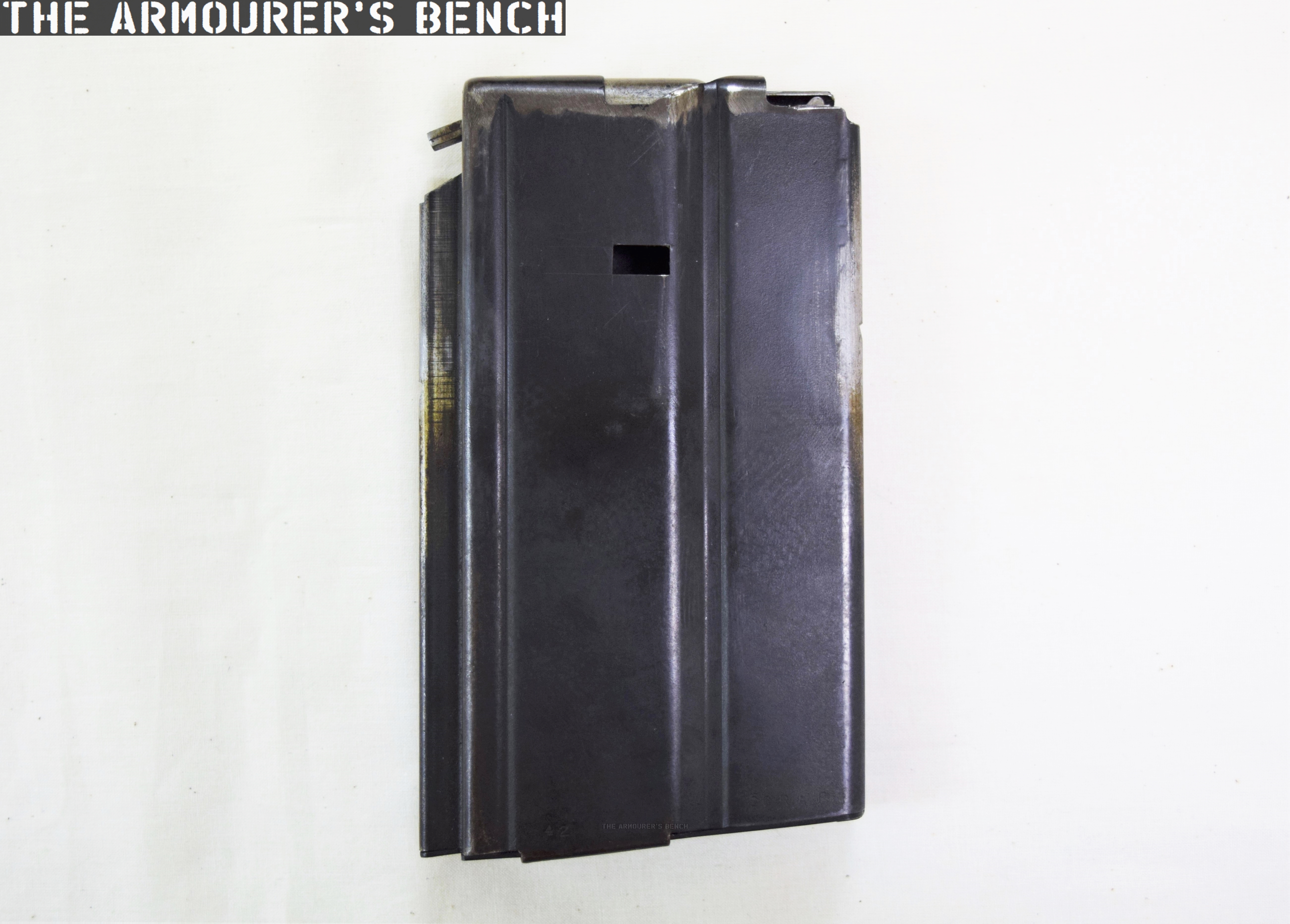
This prototype’s trigger guard assembly, which also comprises the magazine well floorplate, is a self-contained assembly and does not interact with the weapon’s trigger mechanism or action. While Sefried had a patent for his own magazine system (US #2386722) this rifle uses a slightly different magazine release and floorplate, which is similar to one seen in Stefan Janson’s 1956 patent for a stripper clip-loading box magazine for the M1 (US #2894350). The magazine used in this prototype, however, is not the same as Janson’s. It has fixed feed-lips and a projection at its rear which appears to house an anti-tilt tab for the follower.
The rifle’s magazine (Matthew Moss)
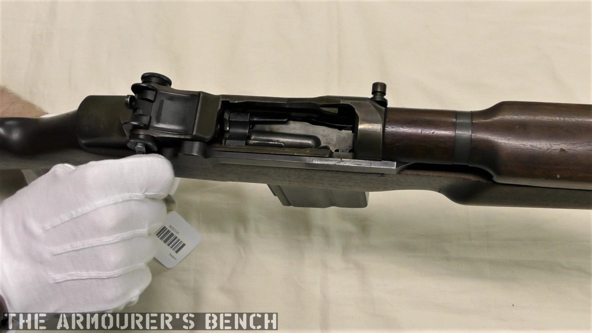
The rifle does not to appear to use the full-automatic system seen in either of Sefried’s patents. Similarly, the safety selector is located on the left side of the receiver, forward, in line with the breech. It has two positions with an arc of about 90 degrees. This position does not match Sefried’s patents for select-fire conversion, however, it does match the position patented by David Marshall Williams but not Williams’ selector’s orientation of travel. I have been unable to find a patent which matches this rifle’s selector or method fully-automatic conversion.
Left-side view of the rifle’s receiver showing the fire-selector (Matthew Moss)
The pistol grip is an interesting addition as neither of the other Winchester select-fire prototypes nor the original select-fire Springfield prototypes incorporated one. Visually it is very similar to that seen on the later Italian Beretta BM 59 Mark II. In an effort to lighten the rifle the prototype also has an aluminium buttplate. One of ingenious internal changes is the milling of the bottom of the barrel flat, this not only has the effect of lightening the rifle but also allows a new, straight operating rod to travel rearwards under the barrel. How this impacted on the barrel’s harmonics is unclear. The rifle certainly feels lighter and handier (when unloaded) than you would expect, weight is estimated to be around 7 or 8 lbs.
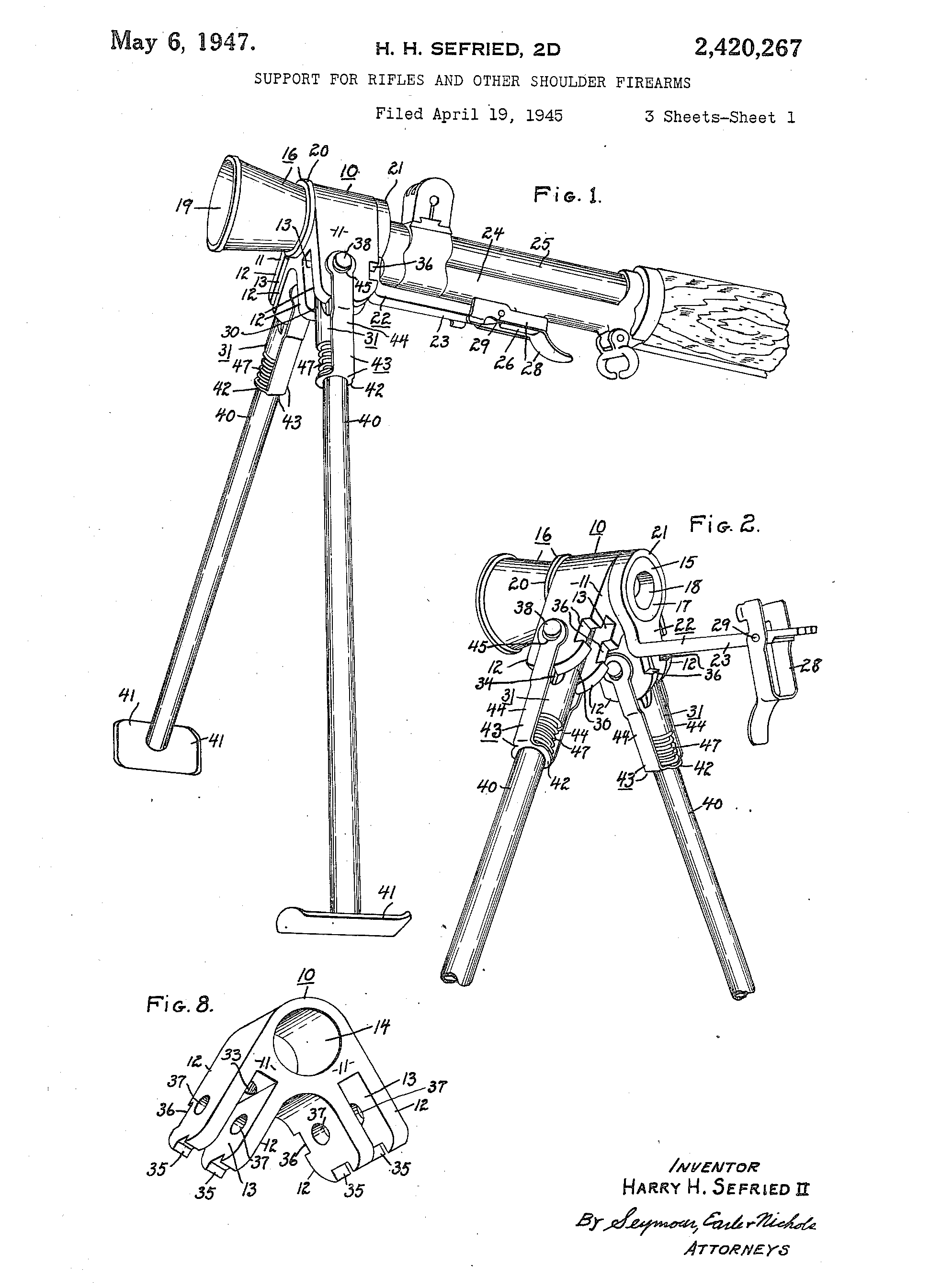
The bipod, patented by Sefried in April 1945, (US #2420267) comprises a pair of tube steel legs, which have a set height, and a conical aluminium flash hider. The legs are spring-loaded and the entire assembly attaches via a latch which seats over the rifle’s bayonet lug. The bipod is the only element of this rifle that can be attributed to Sefried directly. And by the bipod’s very nature of attachment may simply have been attached later.
Sefried’s 1947 patent for the bipod-flash hider (US Patent Office)
The best documentary source available for the prototype is the entry in the Winchester Factory Museum’s collection inventory offers some tantalising clues but no definitive answers:
#1504 U.S. Model M-1 rifle (Garand)
Cal. 30-06; experimental semi or full auto.
3rd type 20 shot box mag.
Special butt plate for shoulder rest
Bipod and aluminum flash hider attached
From H. Sefried 10-26-45
The suggestion that the rifle is chambered in .30-06 is seemingly an error given the internal changes made to the rifle. ‘3rd type’ suggests an iterative development of the rifle’s magazine while “special butt plate for shoulder rest” may allude to the aluminium butt plate but the prototype’s plate has nothing resembling a ‘shoulder rest’, instead it is a simple chequered aluminium plate about 5mm thick. While ‘From H. Sefried 10-26-45’ may refer to the whole rifle, I believe it more likely refers simply to his bipod.
A close up of Sefried’s bipod-flash hider (Matthew Moss)
The prototype appears to be chambered in an iteration of the .30 Light Rifle round, which later became known as the T65. The rechambering was achieved by installing a metal block which shortened the magazine well. Unlike earlier Winchester select-fire conversions this rifle feeds from a proprietary magazine designed to feed the T65 round. This magazine does not appear to closely follow the pattern used by Winchester on several other designs during the period. The projection from the rear of the magazine slides along a channel cut in the metal magazine well block. It has font and rear locking shelves, with the front shelf acted on by the magazine release lever.
A look at the rifle’s receiver and serial number markings from above (Matthew Moss)
With the action open. Note the magazine insert at the rear of the magazine well (Matthew Moss)
Development of the .30 Light Rifle round, which would eventually become 7.62x51mm, began in 1944, with the round first being referred to as the T65 in 1946. It appears that the rifle is chambered in a version of the T65 cartridge, but which iteration exactly is unknown. However, its chambering does support the theory that the prototype may date from 1947-48. The T65 didn’t take on the now standard 7.62x51mm dimensions until 1949 in the form of the T65E3 round but without a chamber casting it is impossible to know the rifle’s exact chambering.
A photo representing the evolution of the .30 light rifle round (Courtesy of DrakeGmbH)
While Winchester continued to work on adapting the M1 Garand into a select-fire rifle none of their rifles were seriously considered by US Ordnance. At the same time John Garand was working on his own series of select-fire, magazine-fed prototypes (the T20 series) at Springfield while Remington had also been awarded a contract to develop a similar rifle, tested under the designation T22. These projects subsequently gave way to a number of other designs, all chambered in the T65 round, including the T25/47, T44 and T48. These were all tested before the Garand-influenced T44 was eventually selected in 1957, becoming the M14.
Addendum:
Harry Sefried II served in the US Army Air Corps during World War Two before joining Winchester as a firearms designer in 1944. In the 1950s he left Winchester to become Ruger’s chief engineer until he retired in 1979. He died in 2005, aged 84.
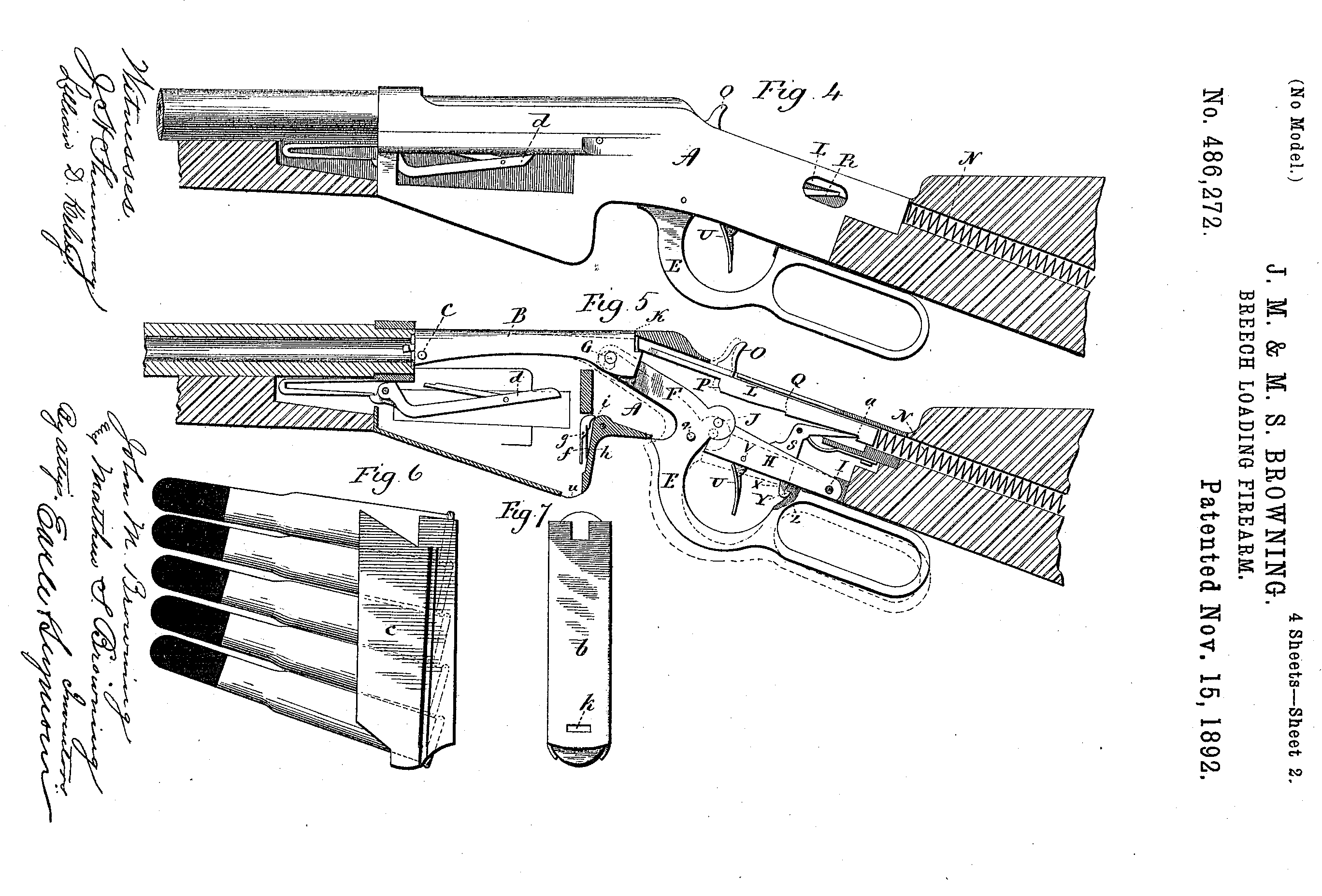
The 1890s were one of John Browning’s most prolific periods, during which he developed a host of firearms which would never actually see production. Here, we’re lucky enough to be able to examine one of those prototypes that were never produced. Dating from 1892, this rifle departs from Browning’s earlier lever-action rifle designs in a number of interesting ways. Perhaps the most interesting aspect of the design is its use of en bloc clips, instead of the tube magazine traditionally used by Winchester’s repeating rifles. John Browning, and his brother Matthew, filed the patent covering the design in June 1892.
Right side of the rifle, note its ‘musket’ configuration (Matthew Moss)
The rifle is in what is typically referred to at the time as a ‘Musket’ configuration, signifying that it is a military long-arm. It has a long 32.5 inch barrel, which is held in place by two barrel bands. Overall the rifle is around 50 inches in length and weighs just over 9lbs. The rifle is chambered in a .30 calibre cartridge, likely the then new .30-40 Krag round given its proposed market. It has a ladder-style rear sight with range graduations from 100 to 1,000 yards.
Browning’s patent drawing showing the rifle’s action (US Patent Office)
Okay, let’s take a closer look at the prototype. During the 1890s Browning experimented with a series of magazine systems including an en-bloc clip system. This rifle uses a 5-round magazine which is fed from an en-bloc clip. The idea of an en-bloc clip was relatively new with Ferdinand Mannlicher patenting the idea in the 1880s and using it in his Model 1886 and 1888 rifles. It is unclear if Browning was familiar with Mannlicher’s system but the two are very similar. If you’re unfamiliar with en bloc clips it means that the cartridges are loaded into the weapon in the clip rather than stripped from the clip.
A look at the ejection port for the en-bloc clip (Matthew Moss)
Browning’s prototype holds five rounds in its clip, which from patent drawings we can see was not reversible. Sadly, we don’t have an example of Browning’s clip to examine but his 1892 patent (see above) gives us a good idea of what it would have looked like. It clearly has a cut at the top of the clip which appears to have been used to help guide the round up into the chamber.
Rounds were pushed up into the action by a follower arm which was actuated by a v-spring located at the front of the magazine housing. The bottom of the fixed magazine housing has a cut-out corresponding to the clip to allow it to fall or be pushed clear by a new clip once it was empty.
The rifle’s lever fully-forward with its action open and striker cocked (Matthew Moss)
The rifle also departs from the traditional hammer system and uses a striker-fired action. From the patent drawings we can see how the rifle’s striker worked, with a coil spring extending into the stock and a sear holding the striker to the rear. The striker is made up of two pieces with the striker hitting a long firing pin inside the bolt.
The striker has, what the patent refers to as, a ‘thumb piece’ to enable re-cocking and to indicate if its cocked or not. The striker was cocked by the cycling of the lever and held in place by the trigger sear.
A view inside the action with the bolt partially retracted before it moves down and back into the rifle’s wrist (Matthew Moss)
The lever was held in the close position, preventing out of battery discharges, by what Browning’s patent calls a downward-projecting dog, which projected through a small hole in the trigger assembly link and locked into a catch in the front of the lever loop.
The use of a striker, rather than an exposed hammer, allows the rifle bolt’s travel to be enclosed rather than have the bolt project out of the rear of the receiver, as in previous Winchester lever-actions, we can see that this rifle’s bolt slides back at an angle partially down into the wrist of the stock. This is arguably more ergonomic and potentially helps to prevent ingress of dirt.
The first half of the lever’s travel pulls the bolt to the rear, while the second part cocks the striker. An arm extending from the lever pushed the bolt rearward until the trigger sear was engaged. In order to give the lever enough throw to open the action far enough to allow a round to be loaded the trigger mechanism has to be pivoted out of the action, much like the earlier Winchester 1886.
The bolt has a pair of trunnions which project from the sides of the bolt, these run inside longitudinal grooves either side of the receiver, while the rear of the bolt is free to angle up and down as it cycles. The action is locked by the rear of the bolt secured against the rear of the receiver, rather than with a rising locking bolt.
Left side of the rifle (Matthew Moss)
During the period Browning was also working on other lever action and, even more unusual, so-called pull-apart actions as well as various magazine types including a revolving magazine, stripper-clip box magazines and of course as we’ve already seen a detachable box magazine-fed rifle. The 1890s were a truly prolific period for Browning.
The design was purchased by Winchester and the Brownings’ patent was granted in November 1892. The gun, like many of Browning’s other designs of the period, never saw production. Making this rifle a rare one-of-a-kind prototype. It’s an elegant design and the action is smooth. When Winchester did finally seek to produce a military lever-action they chose another of Browning’s designs which retained his traditional rear-locking bolt, which became the Model 1895.
This rifle is a unique prototype and it was an honour to examine it. It’s now on display at the newly refurbished Cody Firearms Museum at the Buffalo Bill Centre of the West. Our thanks to the museum for allowing us to film items, like this one, from the museum’s collection.
The rifle we’re examining is one of dozens of designs sold by the Brownings to the Winchesters Repeating Arms Company during their long relationship. This design dates from the early 1890s and represents one of Browning’s numerous attempts to move away from the tube magazine-fed designs favoured by Winchester.
The prototype is based around the lever-actuated vertically sliding locking block patented by Browning in May 1884 and first used by Winchester in the Model 1886. The rifle itself is in the ‘military musket’ configuration with full-length handguards, military sights, a cleaning rod and able to mount a bayonet.
Right side of the rifle (Matthew Moss)
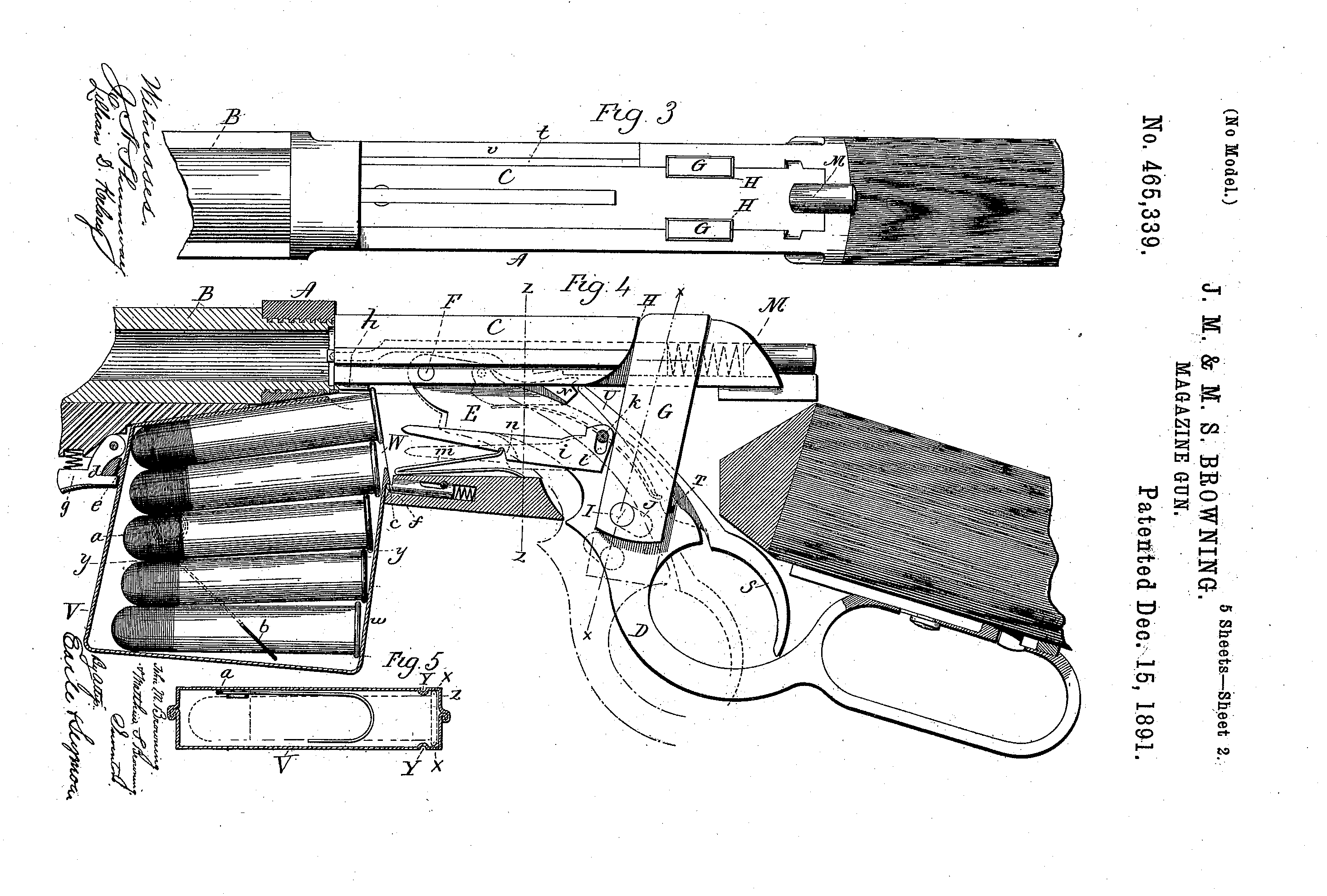
The rifle is chambered in a .45 calibre cartridge, likely .45-70, and weighs just over 9lbs. Browning patented the design of the rifle and magazine in August 1891, with the patent being granted in December (US #465339). It is attributed to John Moses Browning and his younger brother Matthew S. Browning.
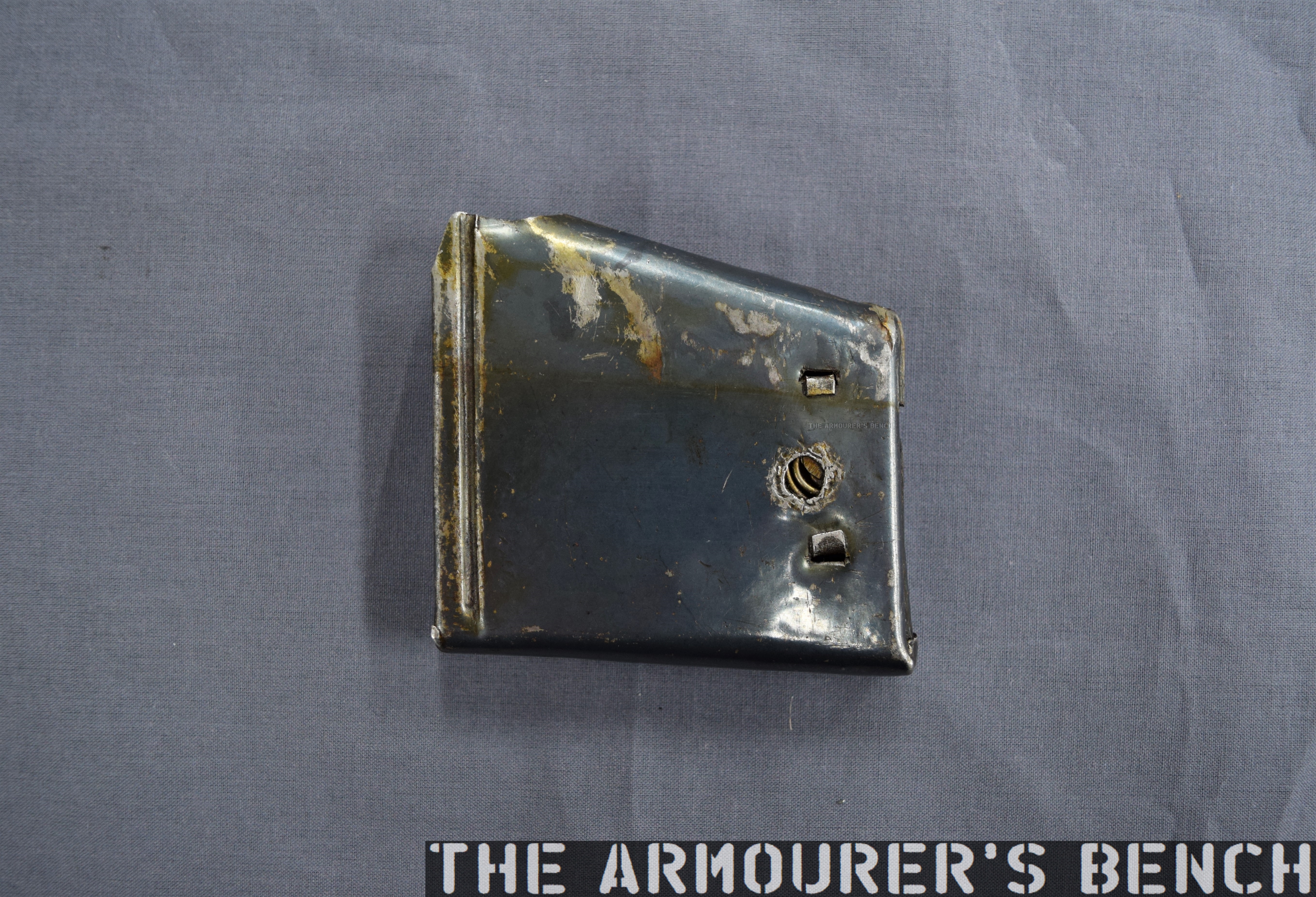
The most interesting feature of the rifle is its detachable box magazine. The magazine is held in place by a spring-loaded catch at the front of the magazine which locks against a tab in the magazine’s wall.
A close up of the magazine well, note the added metal lip of the front of the well, not a part of the receiver (Matthew Moss)
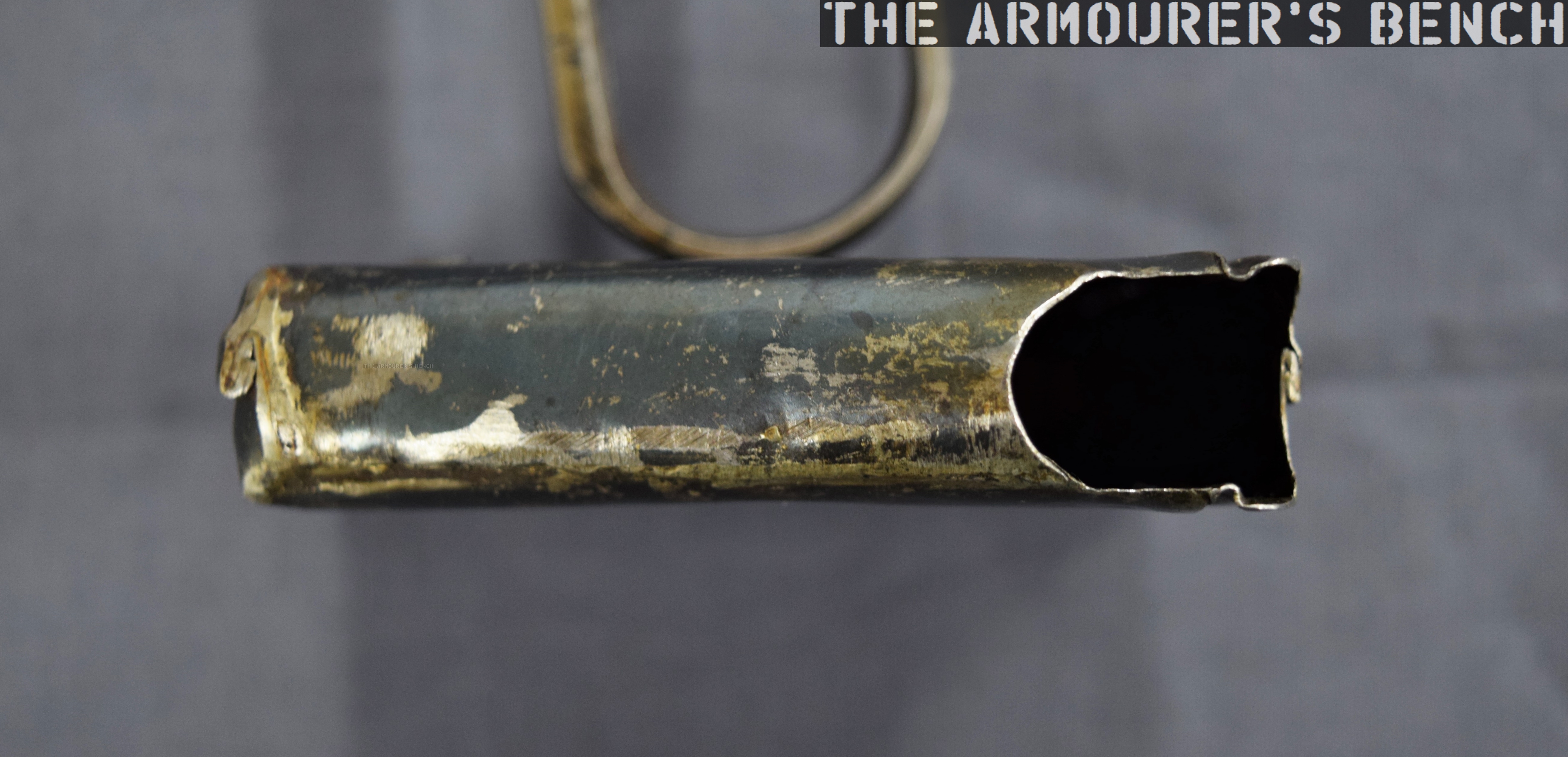
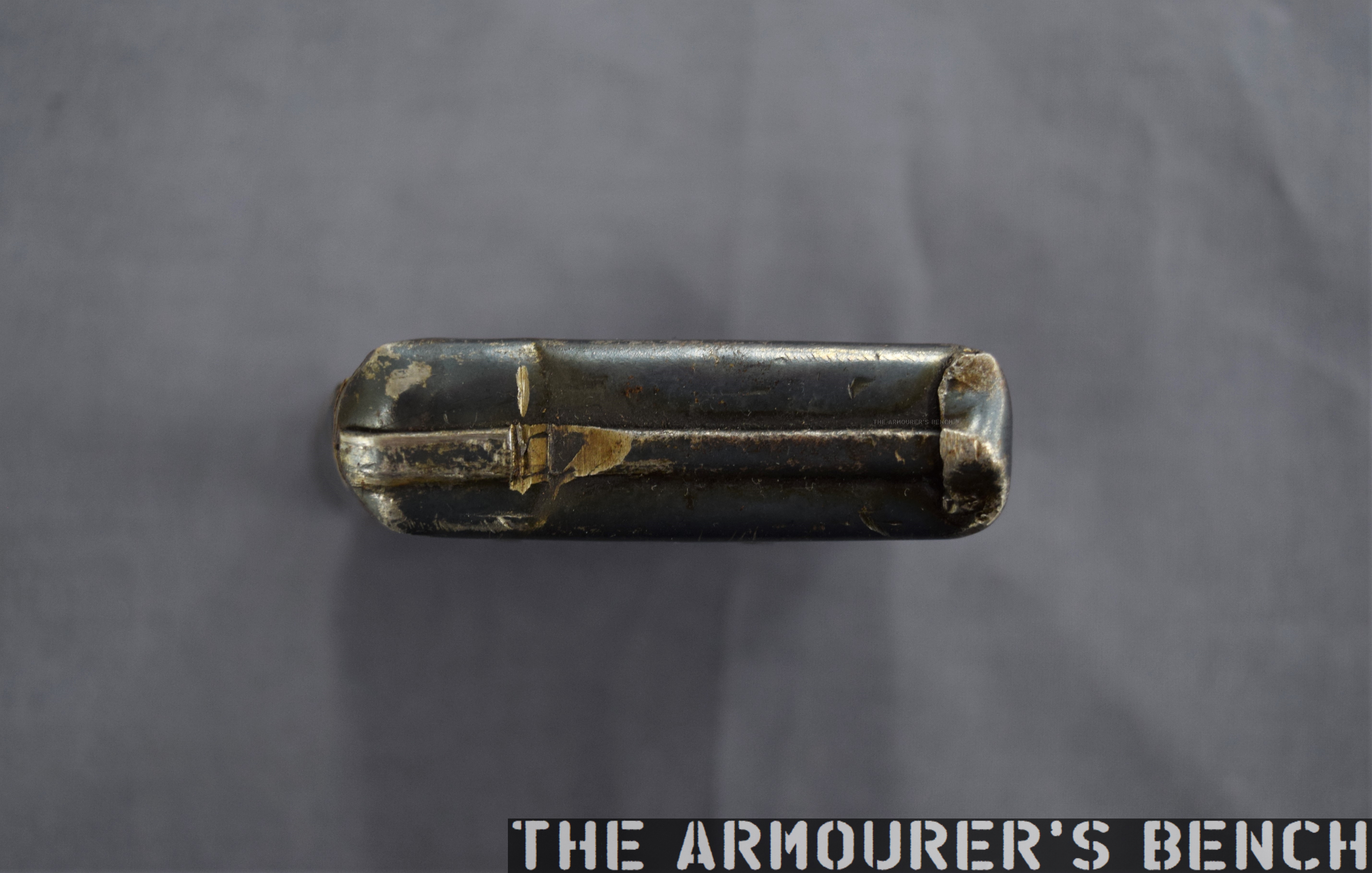
It differs from the box magazines previously developed by James Paris Lee, which Lee begun developing in the mid-1870s (see examples listed below). It’s a simple design with a follower powered by a coil spring. The prototype mag itself is made from pressed metal and is held together with some rough welds. Unlike the magazines we’re familiar with today, the top of the Browning’s magazine is almost entirely enclosed with only a small opening at the rear. The rounds would be loaded nose-first with their rims sliding into the channel at the rear of the magazine.
Close up of the magazine removed from the rifle – right side (Matthew Moss)
A view of the top of the magazine with the small opening and notch for the cartridge rime visible (Matthew Moss)
The single-stack magazine appears to hold around five rounds, with Browning’s patent supporting this. The position of the magazine, in front of the action – not below it, is a hint at how it worked. An almost fully enclosed magazine does have its advantages – it would have prevented dirt from entering the mag and it also overcame the need for feed lips which were susceptible to damage, one of the elements which took Lee some time to perfect.
A close up of the front wall of the magazine, note the locking notch (Matthew Moss)
So How Did The Magazine Work?
There is a shoulder on the underside of the bolt which caught the rim of the cartridge which was protruding from the magazine. The bolt pulled the cartridge backwards, out of the magazine and onto a cartridge lifter. As the lever reached its full forward travel the lifter then elevated the round up into line with the breech. When the lever was cycled back again the round was pushed off the lifter and chambered, just as in a normal tube-fed Winchester. As the lever reached the end of its return travel the locking block rose to locked the action.
The Browning’s 1891 patent for the magazine, note ‘h‘ is the shoulder which pulled rounds out of the magazine (US Patent Office)
The prototype has a sliding safety bar that locks the lever and blocks the trigger. The trigger differs from the Model 1886 as it is integrated with the lever. In the photograph below we can see the locking block descended, with the lever forward, and the breech block to the rear with the action open. We can also see the striker assembly at the rear of the bolt. The striker cocks on closing when the lever is returned rearward.
The rifle with its action open, bolt o the rear and lever forward. Note the striker assembly at the rear of the bolt (Matthew Moss)
It’s quite an exposed action, with the entire top of the action open. With the action closed in the photograph below we can see the extractor running along the right side of the bolt.
A close up of the rifle’s receiver which is still ‘in the white’ (Matthew Moss)
It’s clear from the design of the magazine that Browning didn’t intend the rifle to be reloaded with stripper clips, although single loading of the rifle itself (not the magazine) would have been possible. When compared to other contemporary system this would have been somewhat of a disadvantage compared to Lee’s magazine’s later loading with chargers and stripper clips. However, from examination of Browning’s 1891 patent his intention becomes clear, the patent explains that he intended for the magazine itself to be replaced:
“One magazine may be readily removed from the gun and another introduced in its place, so that the person, using the arm may have at hand several magazines to be interchanged as the cartridges from one magazine are exhausted.”
This is a concept that wouldn’t be accepted by militaries for decades. Winchester purchased the rights to the design but this was one of many designs Browning sold the company which never saw production. The design and prototype are fascinating and represent one of Browning’s lesser-known concepts.
Left side profile of the rifle (Matthew Moss)
This rifle is a unique prototype and it was a true honour to examine it. It’s now on display at the newly refurbished Cody Firearms Museum, at the Buffalo Bill Centre of the West. The new museum is phenomenal and well worth a visit. Our thanks to the museum for allowing us to film items, like this one, from the museum’s collection.
During a recent discussion over on the HF Twitter page, I was informed to my surprise that the Sterling submachine gun had been added as a DLC weapon to Call of Duty WW2. I thought it would be interesting to take a look at the model used in the game and see how historically accurate it is. I recently finished writing a book about the Sterling and have done some research into the theories of the Patchett prototypes seeing some action during the war.
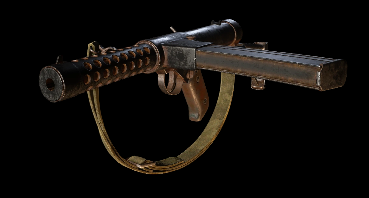
The model that Sledgehammer Games, the developer, have used appears to be a mix of the early prototypes and the later production Sterlings. In terms of historical accuracy the gun should be correctly referred to as the Patchett Machine Carbine – after its designer George Patchett. It only began to be called the Sterling, after the company that manufactured it in the 1955.
Developer’s model of the COD: WW2 Sterling SMG (courtesy of Activision/Sledgehammer Games)
The model appears to share some similarities with the original Patchett prototype, including the step in the welded together receiver – the result of using left over Lanchester machine carbine receiver tubes, which was also built by Sterling. The position of the stock hinge point also appears to be in the correct place (it was later moved forward when the stock was modified). However, it appears to be feeding from a much later curved commercial pattern Sterling magazine (you can tell by the zigzag outline on the rear of the magazine and of course the curve – although seemingly not quite as curved as the real thing.) In reality the Patchett prototypes fed from Sten magazines, it wasn’t until after the war that Patchett designed his excellent 34-round magazine.
Here’s a photo of the Patchett’s original tool room prototype that I took last year while researching:
Patchett’s Original Toolroom prototype (Matthew Moss)
Note how they even replicated the slanted brazed on rear sight that was added after the first trials. The game developers, however, added a metal guard tab just in front of the ejection port – something that wasn’t added until later and they also gave the gun markings on the magazine housing that mimic the later commercial Sterling markings.
The game model also has the Sterling’s helical grooves on its breech block, something the early prototypes did not have. It seems the developers mashed together the Patchett prototype with later production Sterling L2A3/Mk4s.
Did the Patchett See Action During WWII?
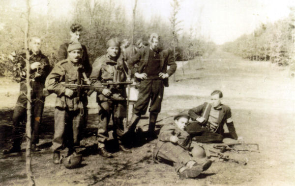
A grainy photograph, sadly lacking provenance, that appears to show members of the Free French SAS with two Patchett prototypes during Operation Amherst, April 1945 (source)
While the early Patchett prototypes may have seen action in late 1944 – 1945 with one or two prototypes possibly making it into the hands of specialist troops there is no solid evidence to support this. There is a tantalising grainy photograph of what is believed to be members of the Free French SAS on operations in the Netherlands in April 1945 (during Operation Amherst). The photo above shows what appear to be two Patchetts during a meeting with local resistance members. There is also an uncorroborated story that one prototype was carried by Lt.Col. Robert Dawson, officer commanding No.4 Commando, during Operation Infatuate but there is no documentary evidence to support this. I discuss these and several other pieces of evidence that support the idea that the Patchett/Sterling saw action in my new book on the Sterling.
I have written a book for Osprey’s Weapon series looking at the development, use and significance of the Sterling, it’s available now, you can find out more about it here.
Our thanks to the collection that holds the G11 for the privileged and nerve-wracking opportunity to field strip it and take a look inside. If you’d like to know more about the history of the G11’s development you can check out our video and full blog on it here. Vic has done a great series of videos looking at the G11 and the other prototype rifles from the US Army’s abortive Advanced Combat Rifle trials – you can find those here.
In this blog we’ll take a closer look at some of the G11’s components, for a demonstration of dissassembly and and explanation of how the rifle works in principal check out the video above.
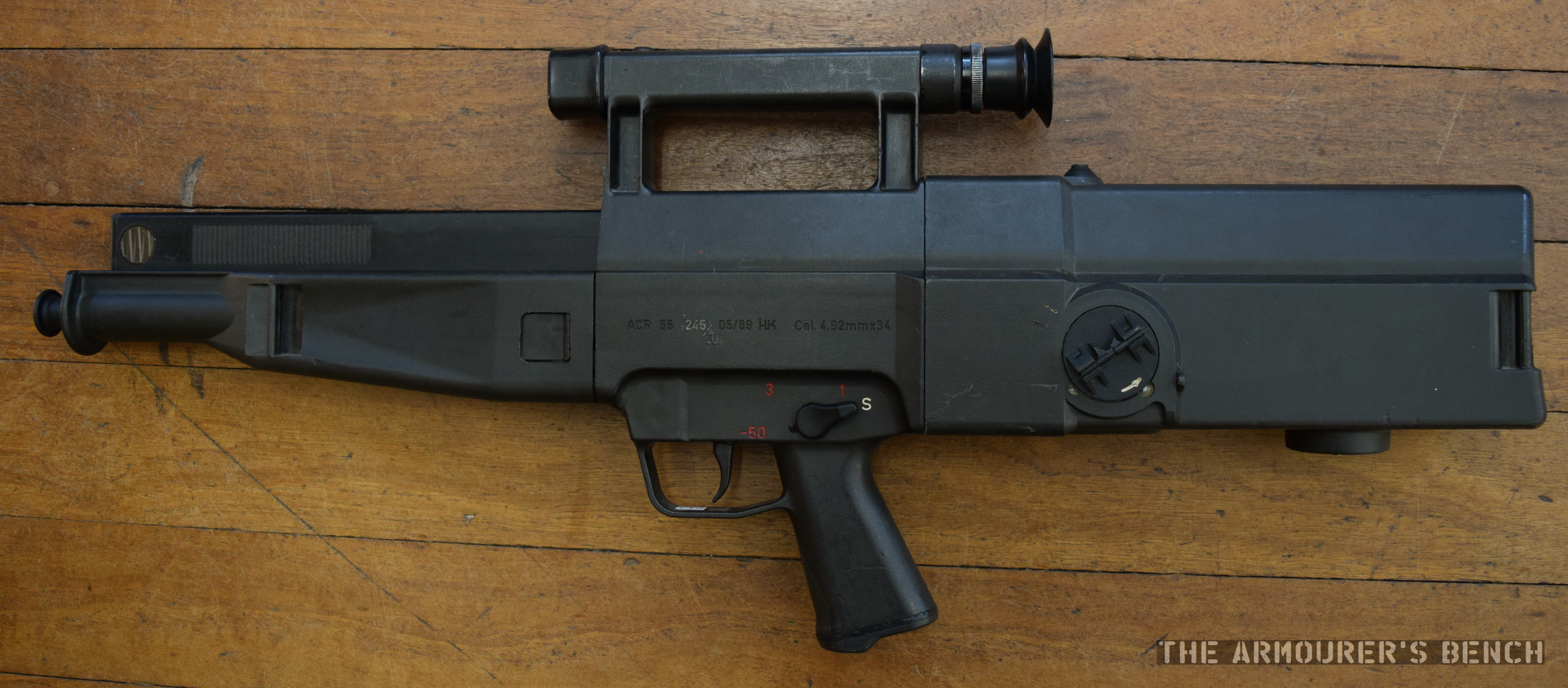
Firstly, lets take a look at the exterior of the rifle. The weapon has a box-like polymer coated outer shell. The shell is made up of three parts, with the butt assembly and forend locking into the centre assembly which includes the pistol grip, trigger mechanism and optical sight. The forend and butt are locked into the centre assembly by plastic locking tabs. While stiff and somewhat difficult to depress the tabs are reportedly prone to breaking.
Left side view of the G11 (Matthew Moss)
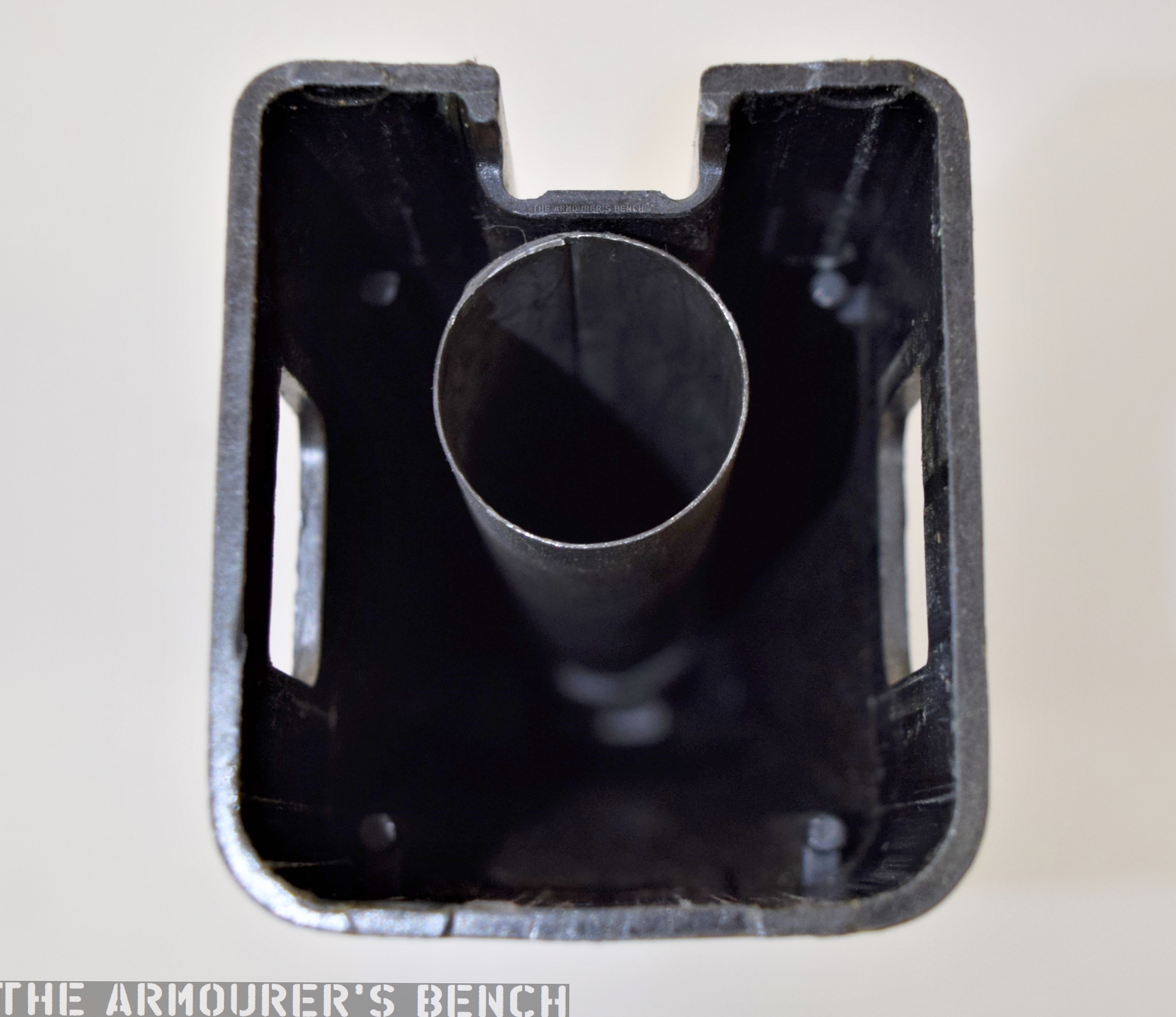
Before we look at the G11’s internals lets take a look at the shell components. Here we can see the inside of the forend, we can see a metal (aluminium I believe) barrel tube into which the barrel slides.
Close up of the the inside of the G11’s forend (Matthew Moss)
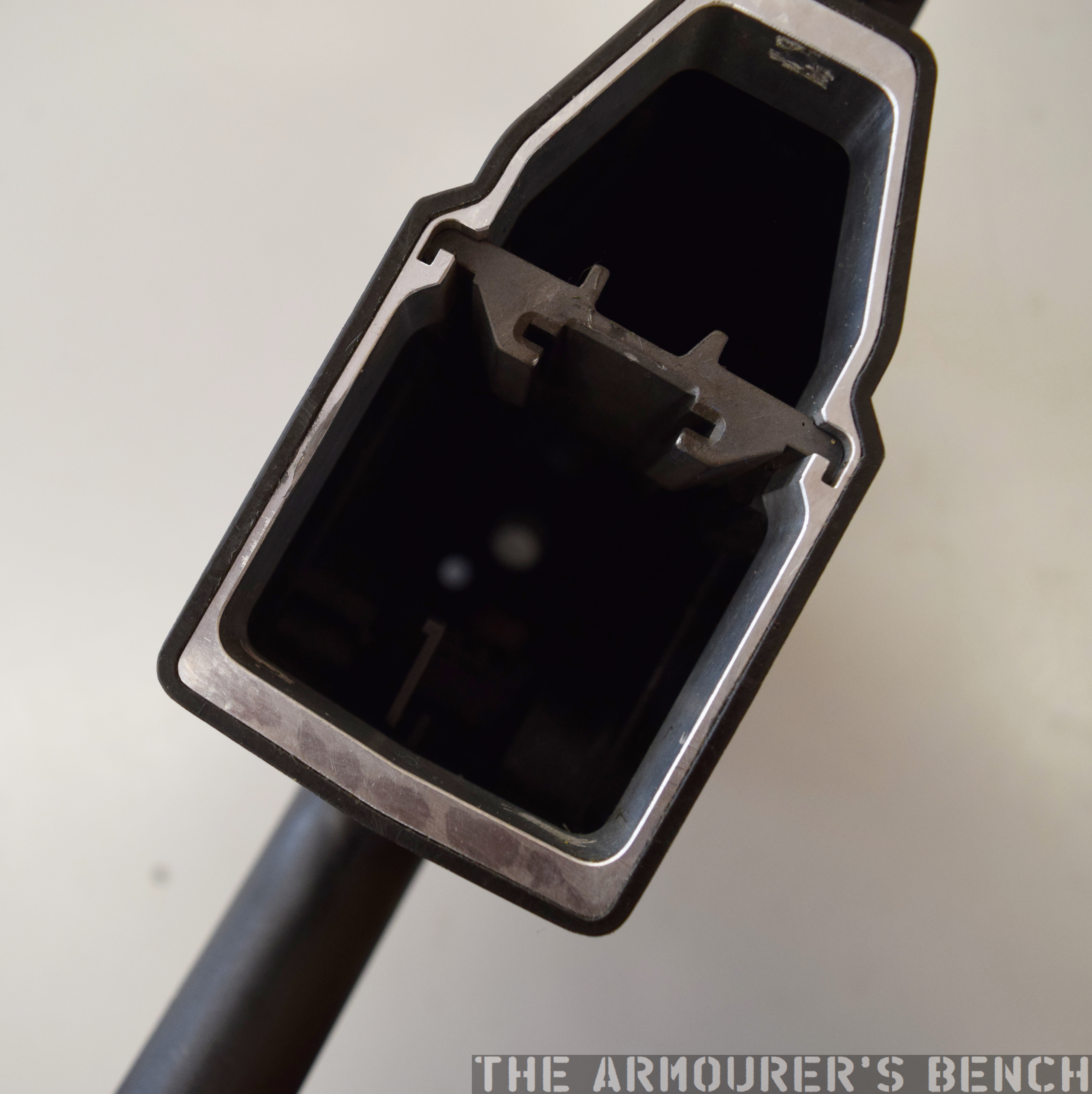
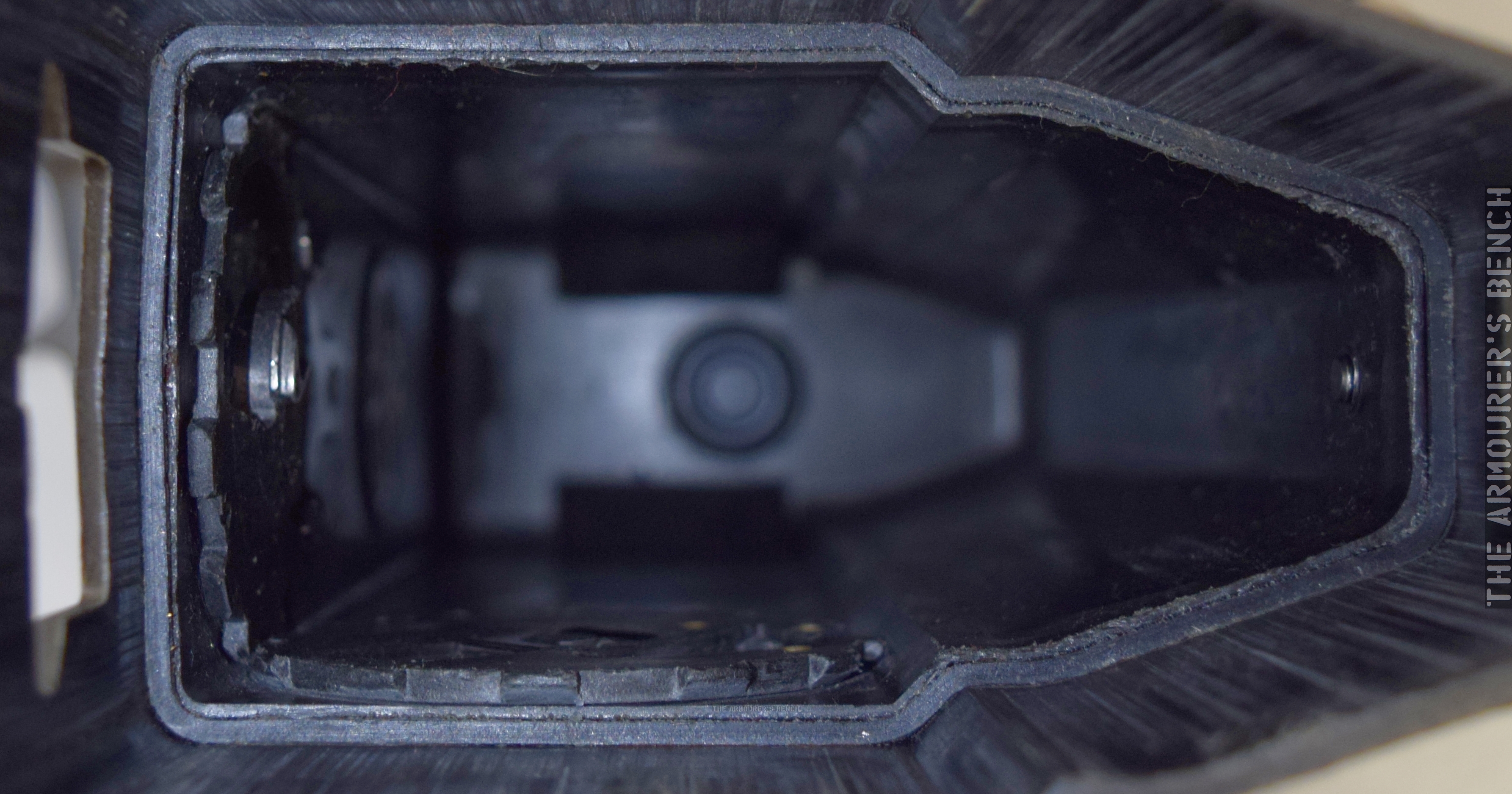
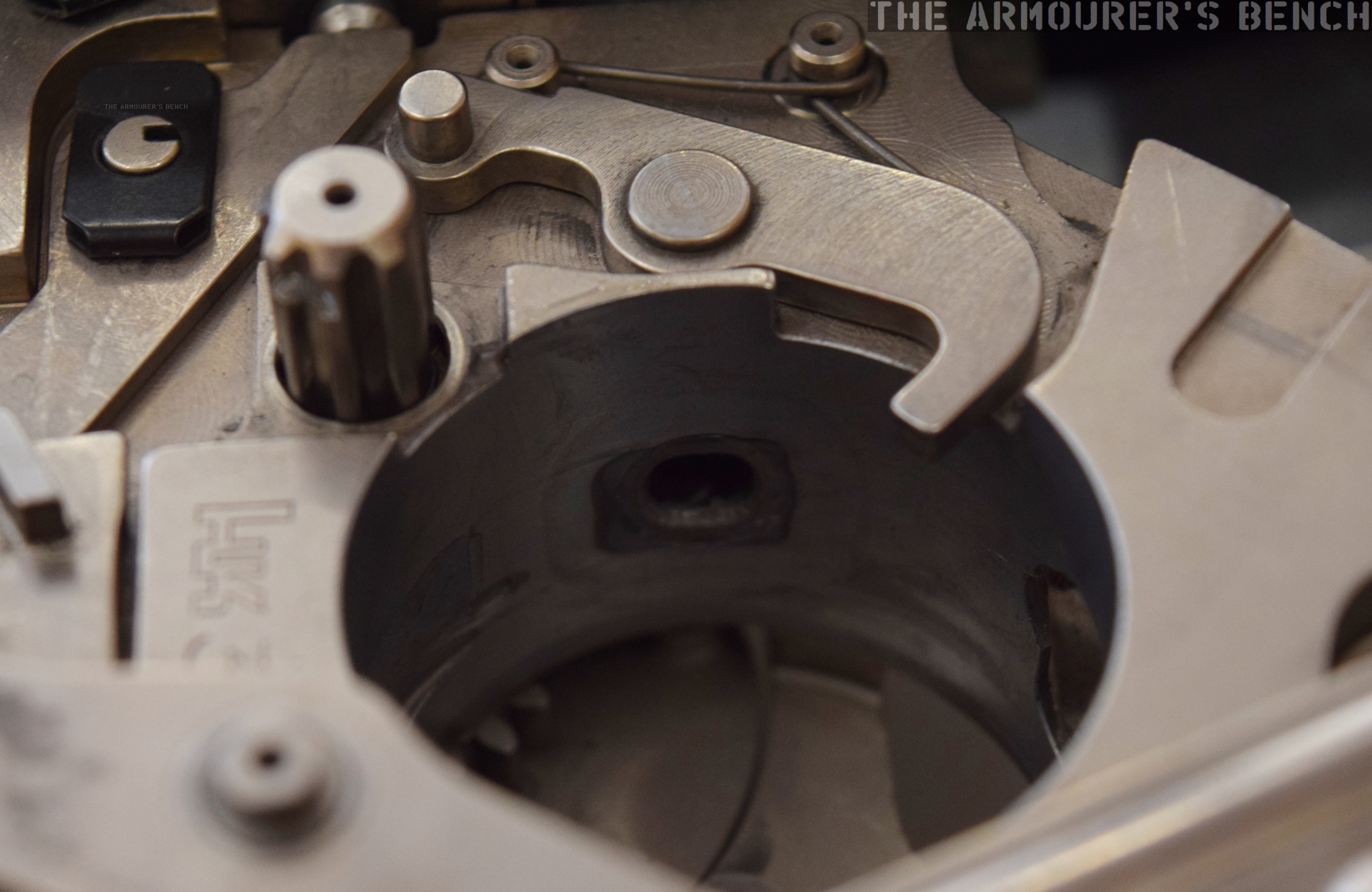
Below is a photograph of the rear of the centre assembly looking forward, the small white circle (sadly slightly out of focus) is the bushing the barrel protrudes through into the forend.
The G11’s centre assembly houses a metal guide rail and magazine guide as well as the trigger mechanism (Matthew Moss)
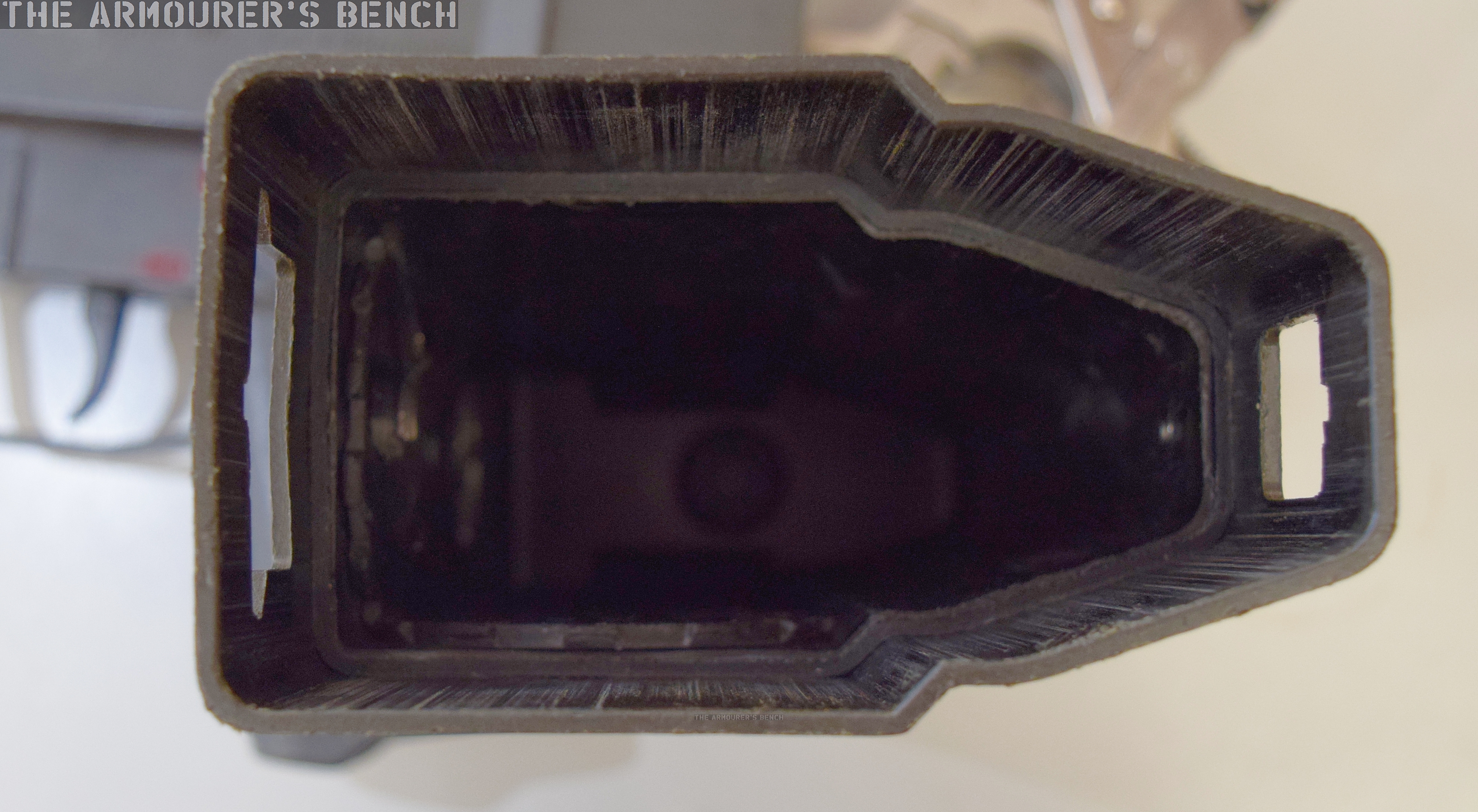
Next we have a view of the inside of the rifle’s butt assembly. Note the scuff marks on the inside where the centre assembly has scrapped the plastic. We can also see the locking tab windows which are on the top and bottom of the butt.
A view inside the G11’s butt stock (Matthew Moss)
Inside the butt we can see the ‘toothed wheel’ and ‘sealing gear’ which are turned when the cocking piece is rotated. These plastic pieces act directly on the action. Behind that is the gas escape valve, which will tap off excess gas if over pressure problems occur with the rifle.
A close up of the sealing gear and toothed wheel that interface with the cocking handle (Matthew Moss)
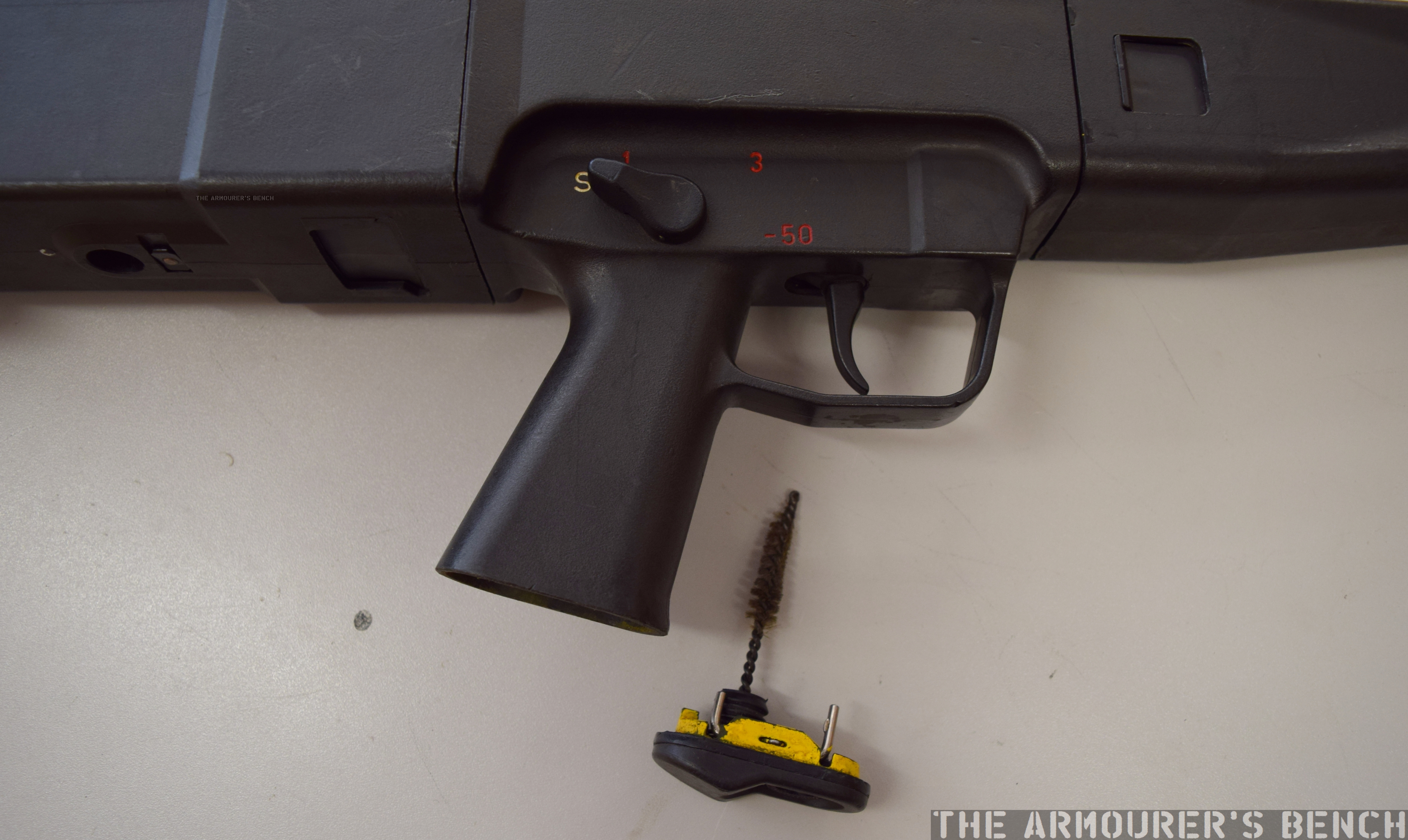
The first step to disassembling the G11 is ensuring the weapon is clear by pushing the cleaning brush up into the breech.
Close up of the G11’s cleaning brush, housed inside the pistol grip (Matthew Moss)
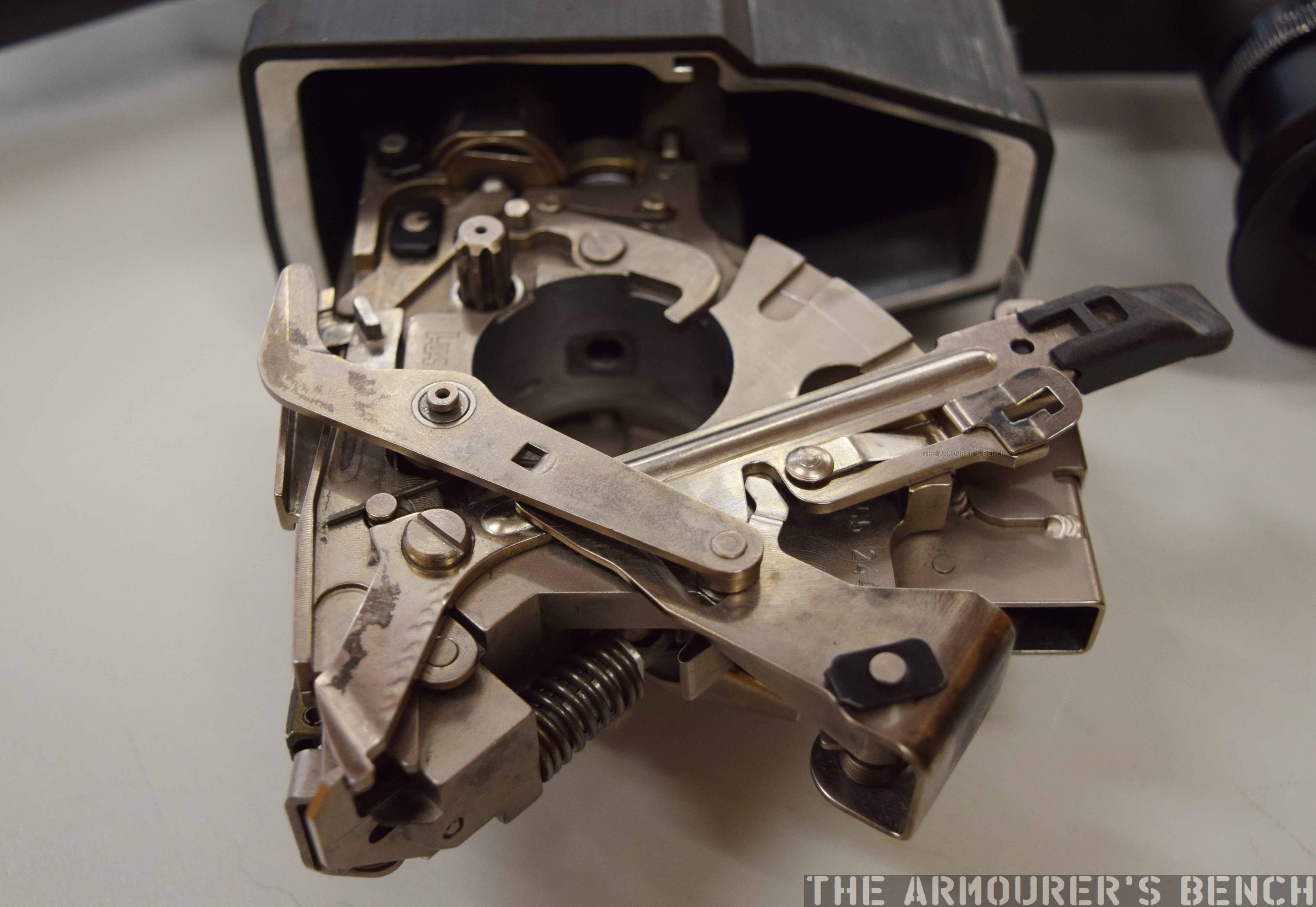
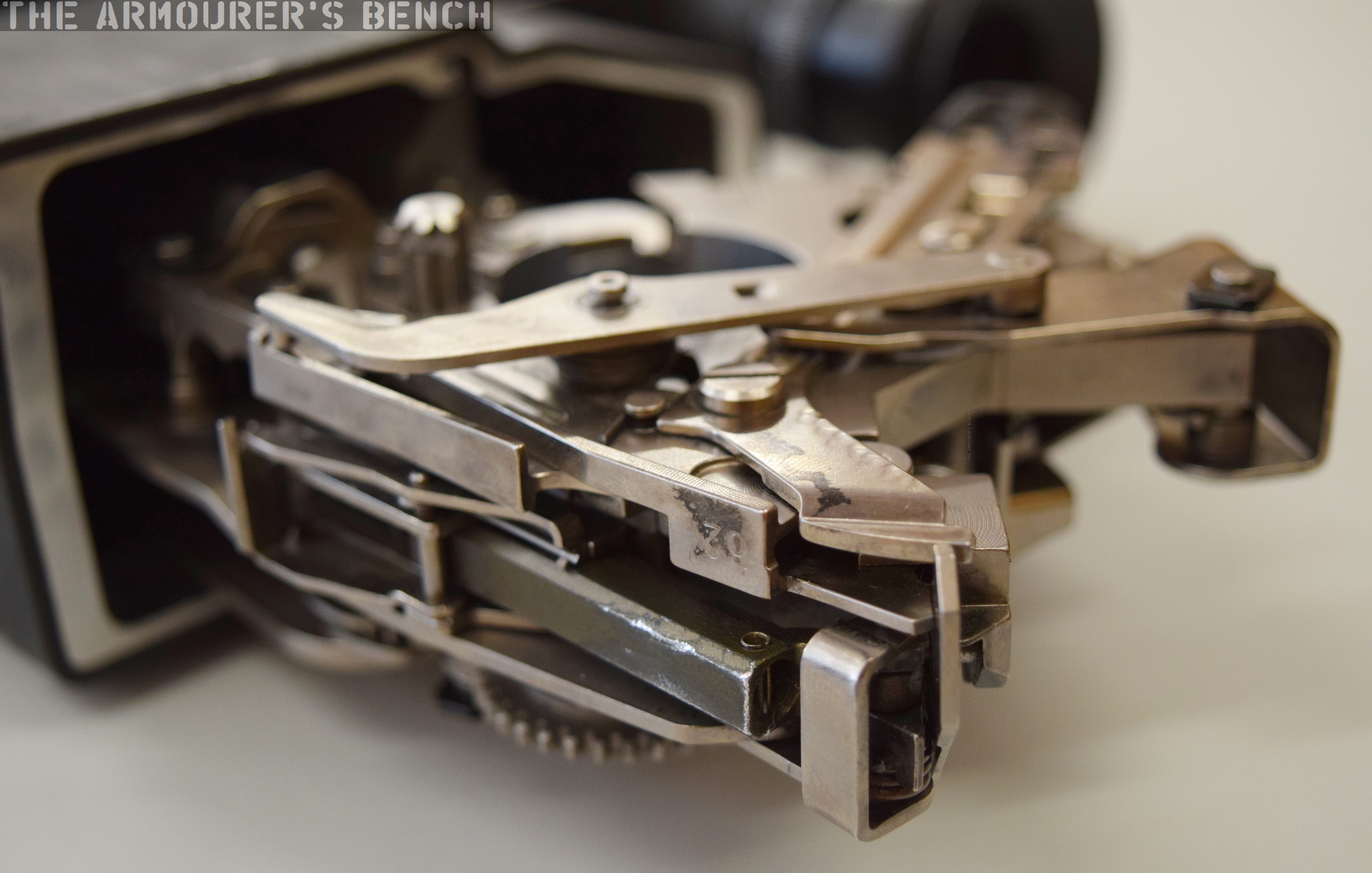
Lets now take a look at the rifle’s action up close, below we can see the G11 with its forend and butt assembly removed. Next to it is the breech cylinder and control disk.
The G11 field stripped (Matthew Moss)
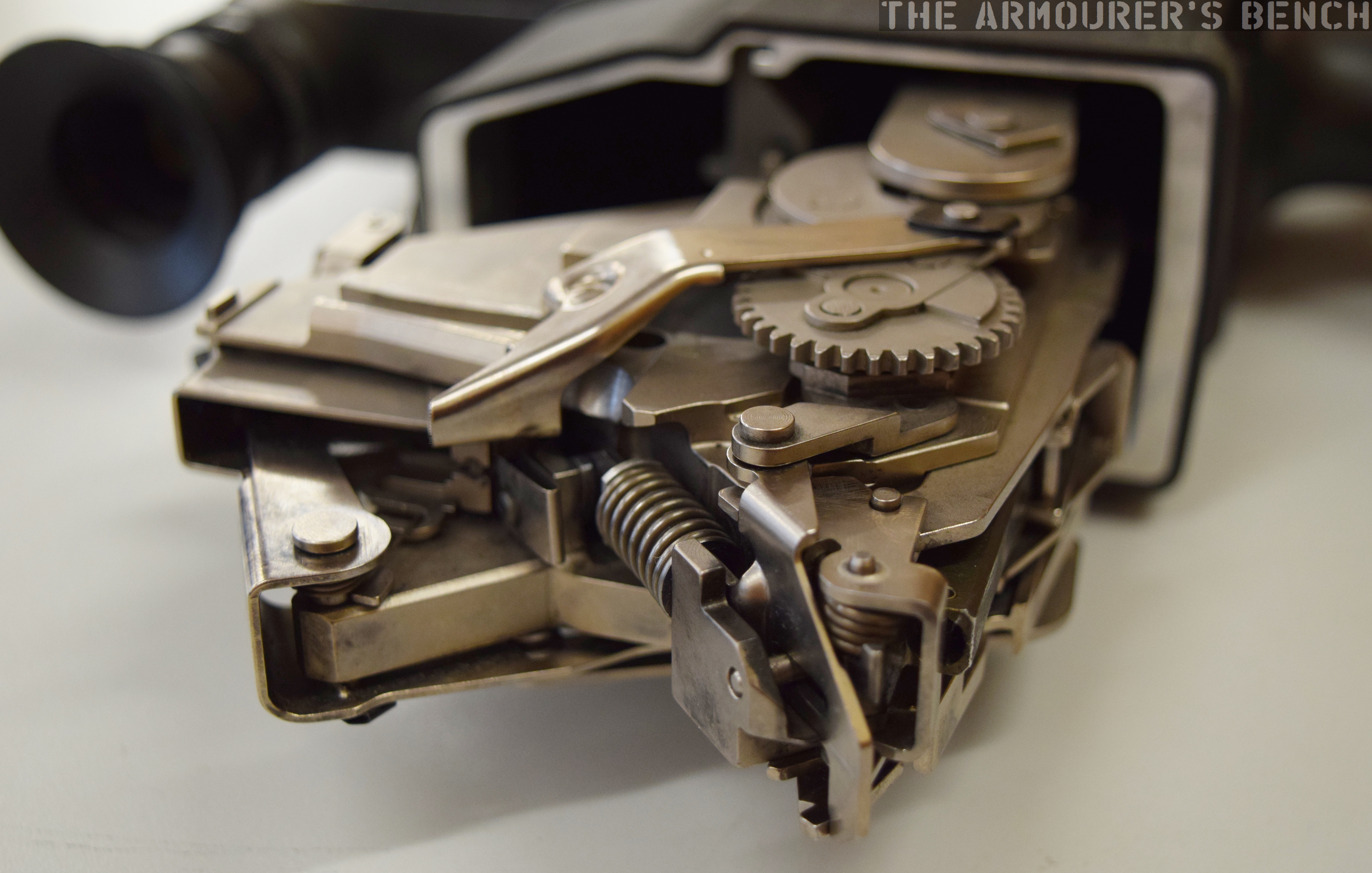
Here are some photos of the action from various angles:
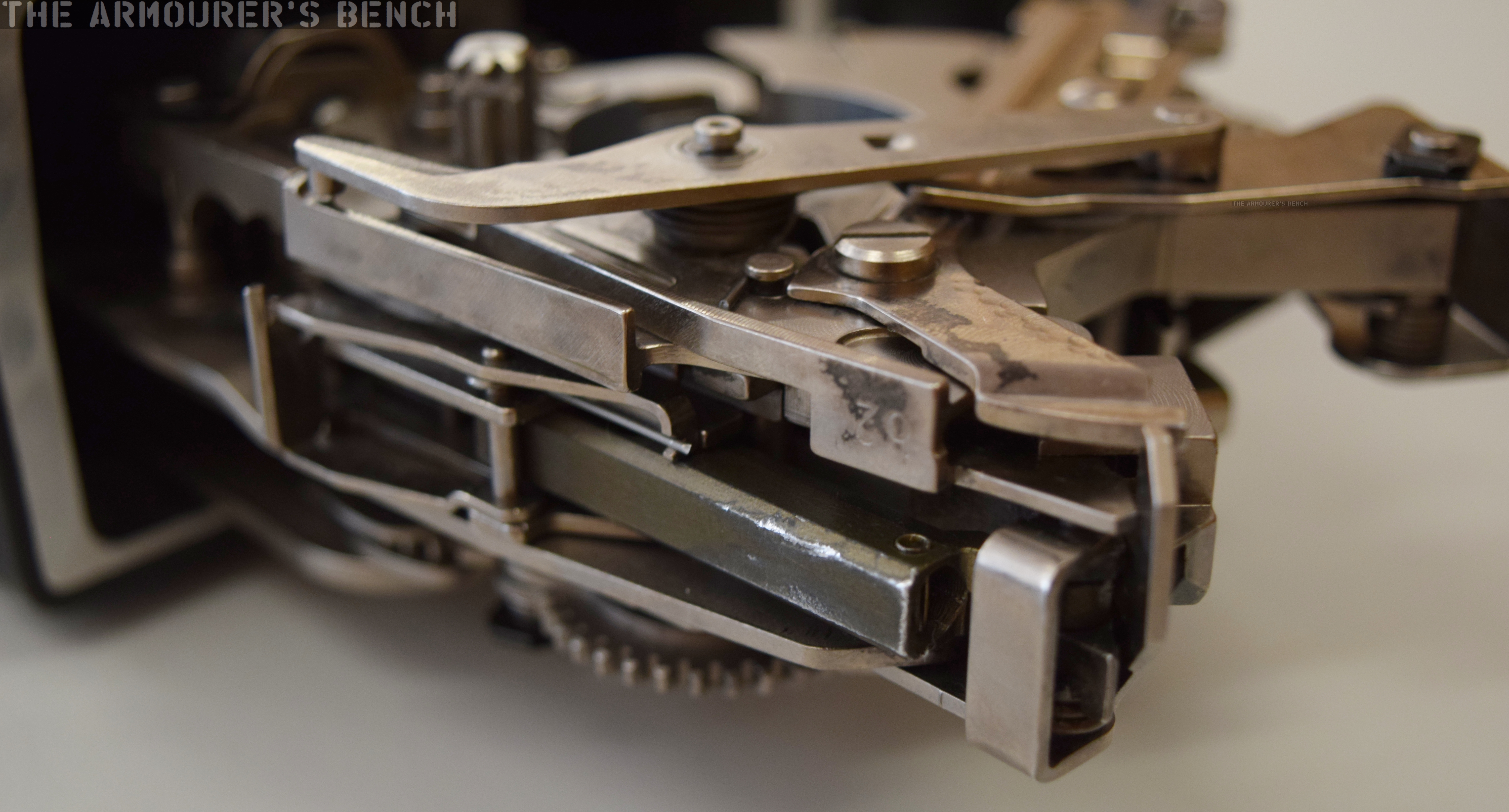
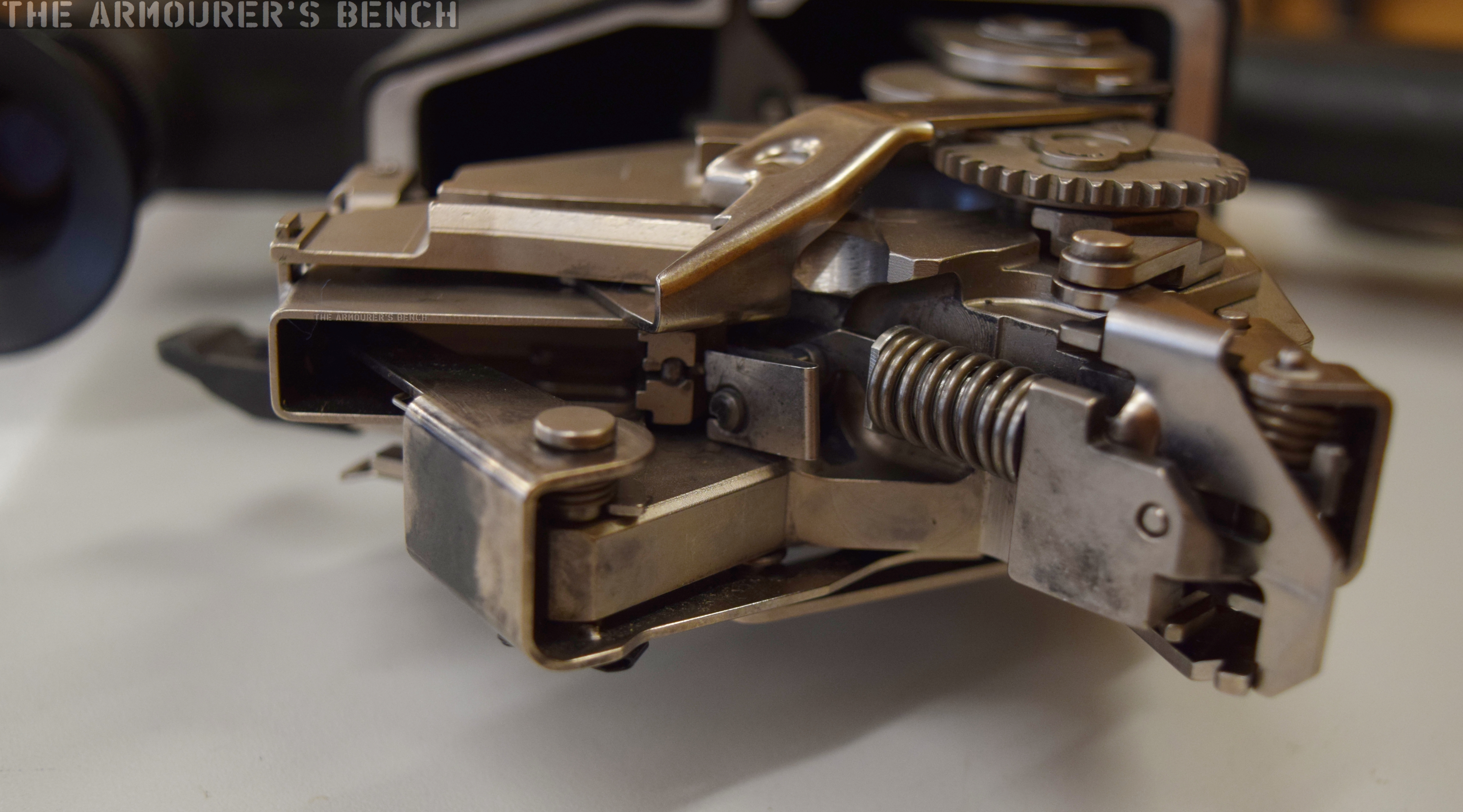
A view of the action from the rear. We can see the striker assembly, clamping plate, ejector lever and cylinder retaining catch (Matthew Moss)
From the right side of the gun we can see the two gears which work the breech cylinder – the spur gear and the actuating gear (Matthew Moss)
On the underside of the action we can see the rear of the clamping plate, the slide – which is slightly worn, and the sear projecting below it (Matthew Moss)
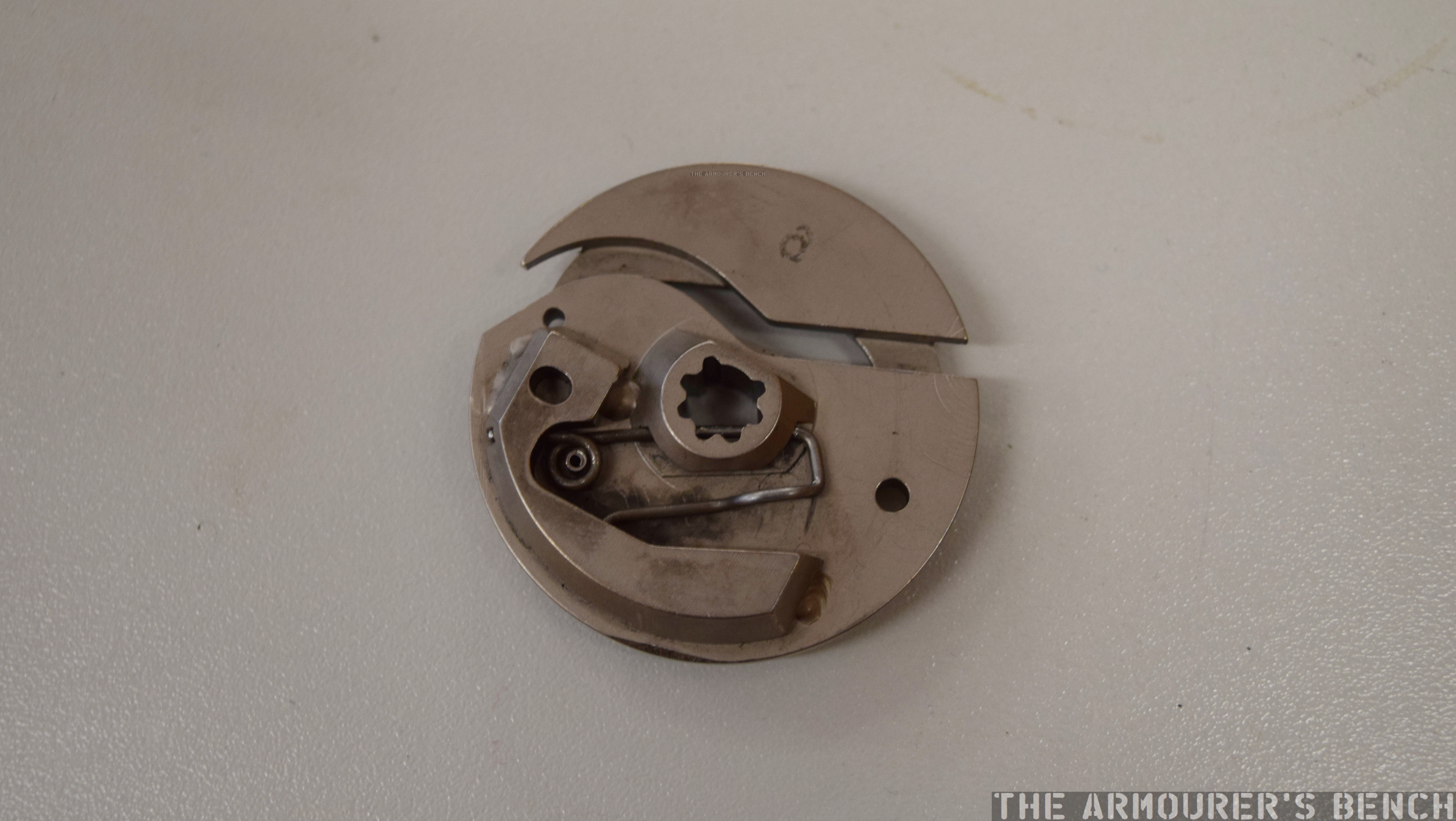
Here’s some close ups of the breech cylinder and control disk:
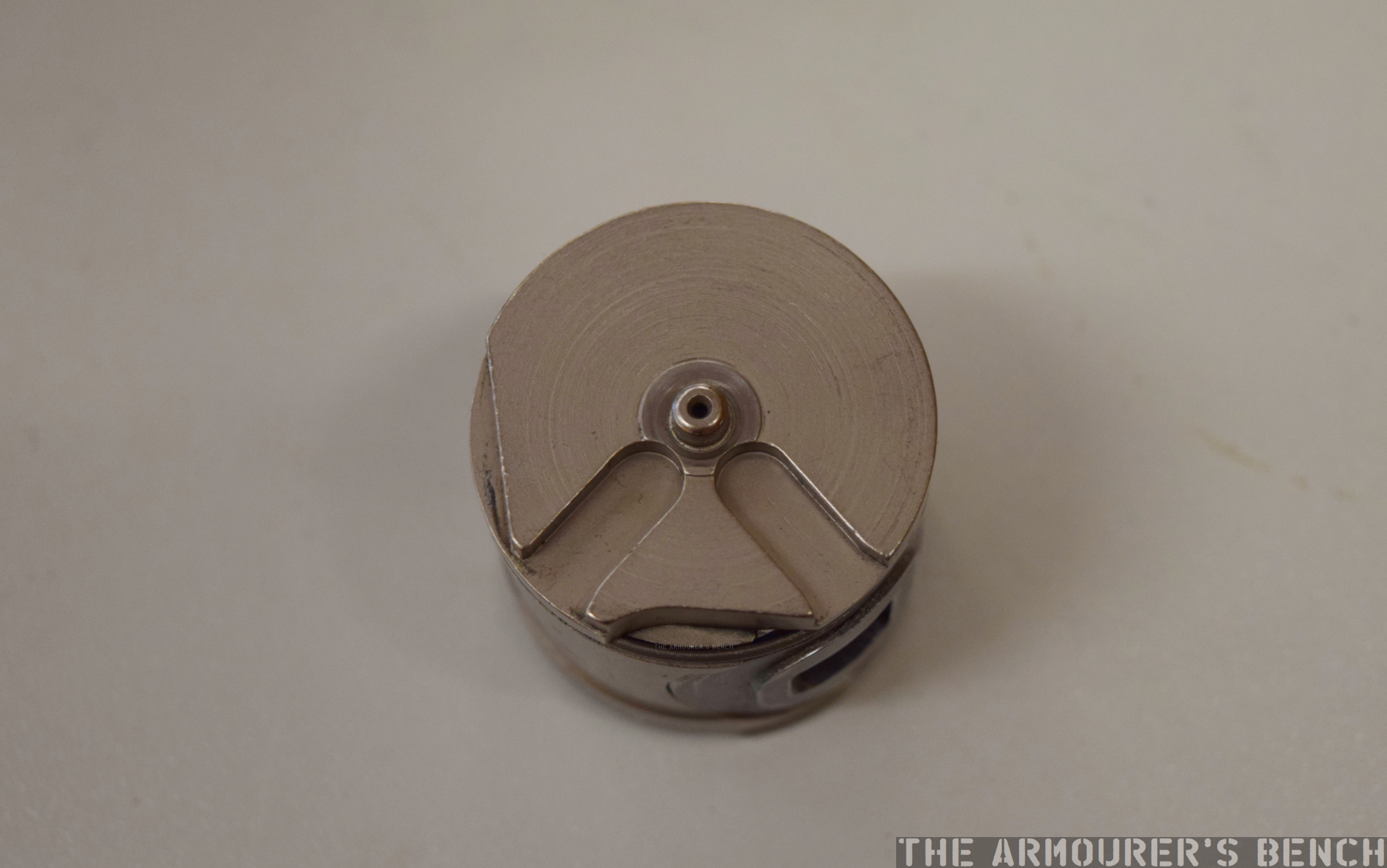
The top of the control disk, which has to be removed before the breech cylinder can be (Matthew Moss)
Underside of the control disk (Matthew Moss)
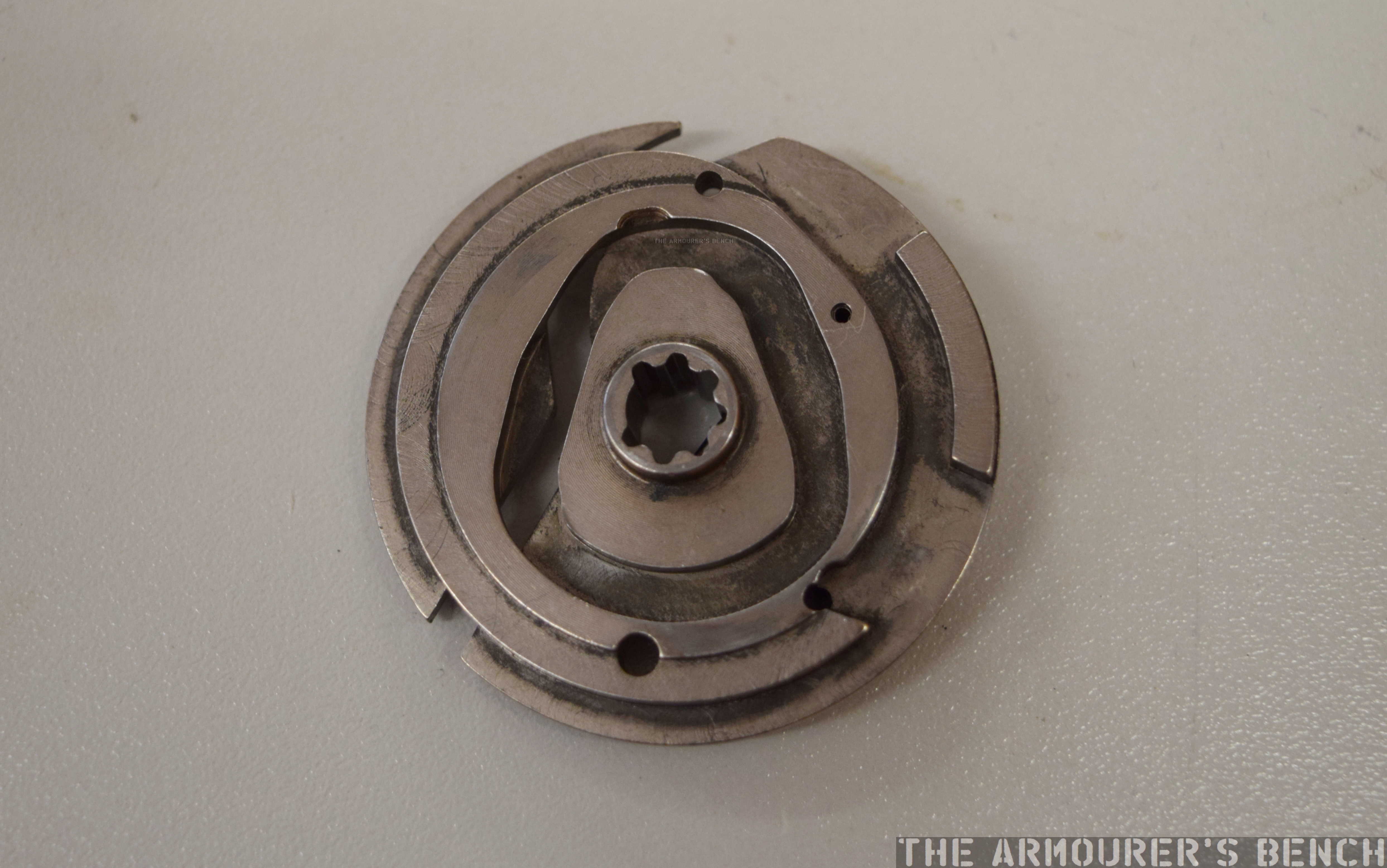
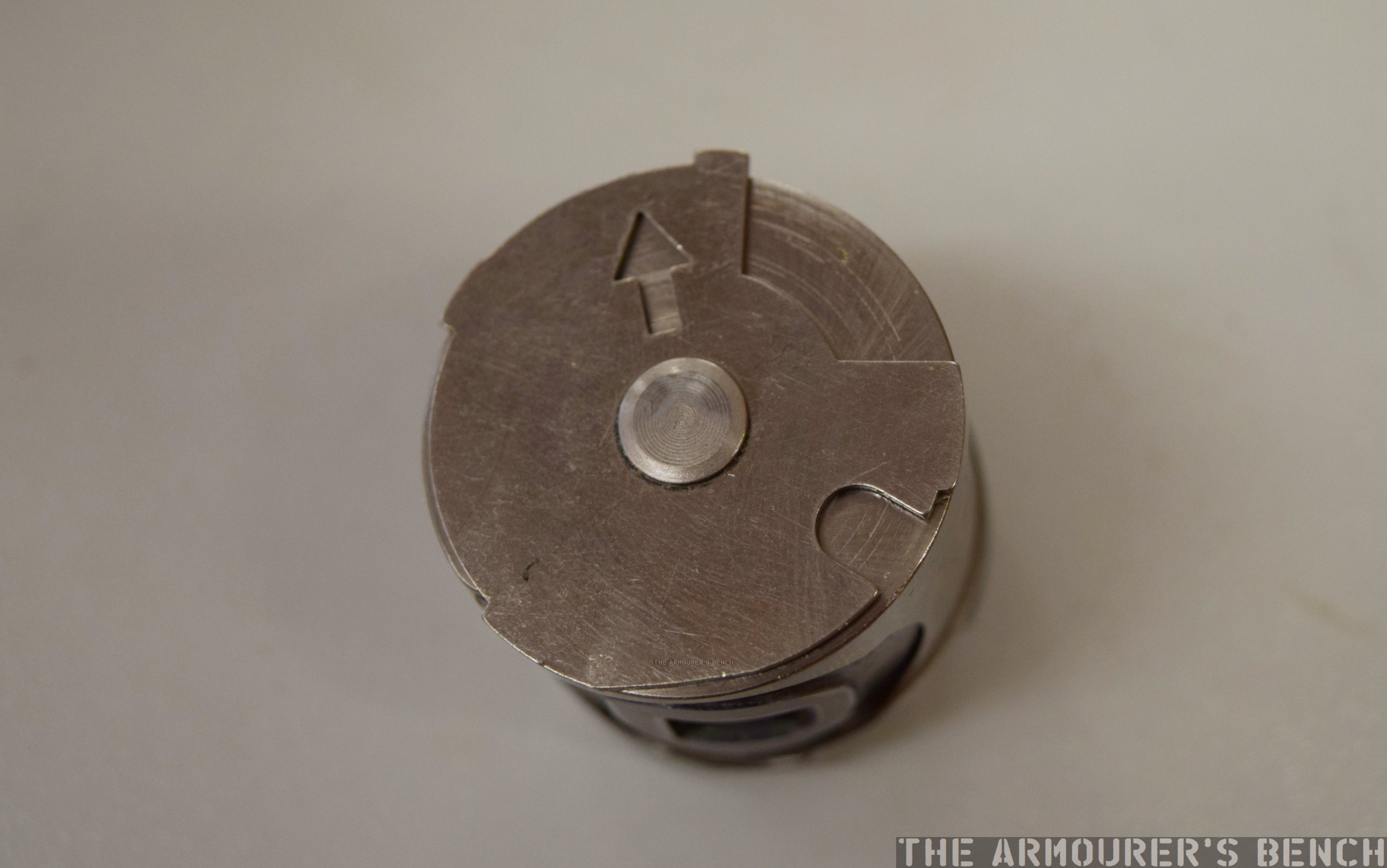
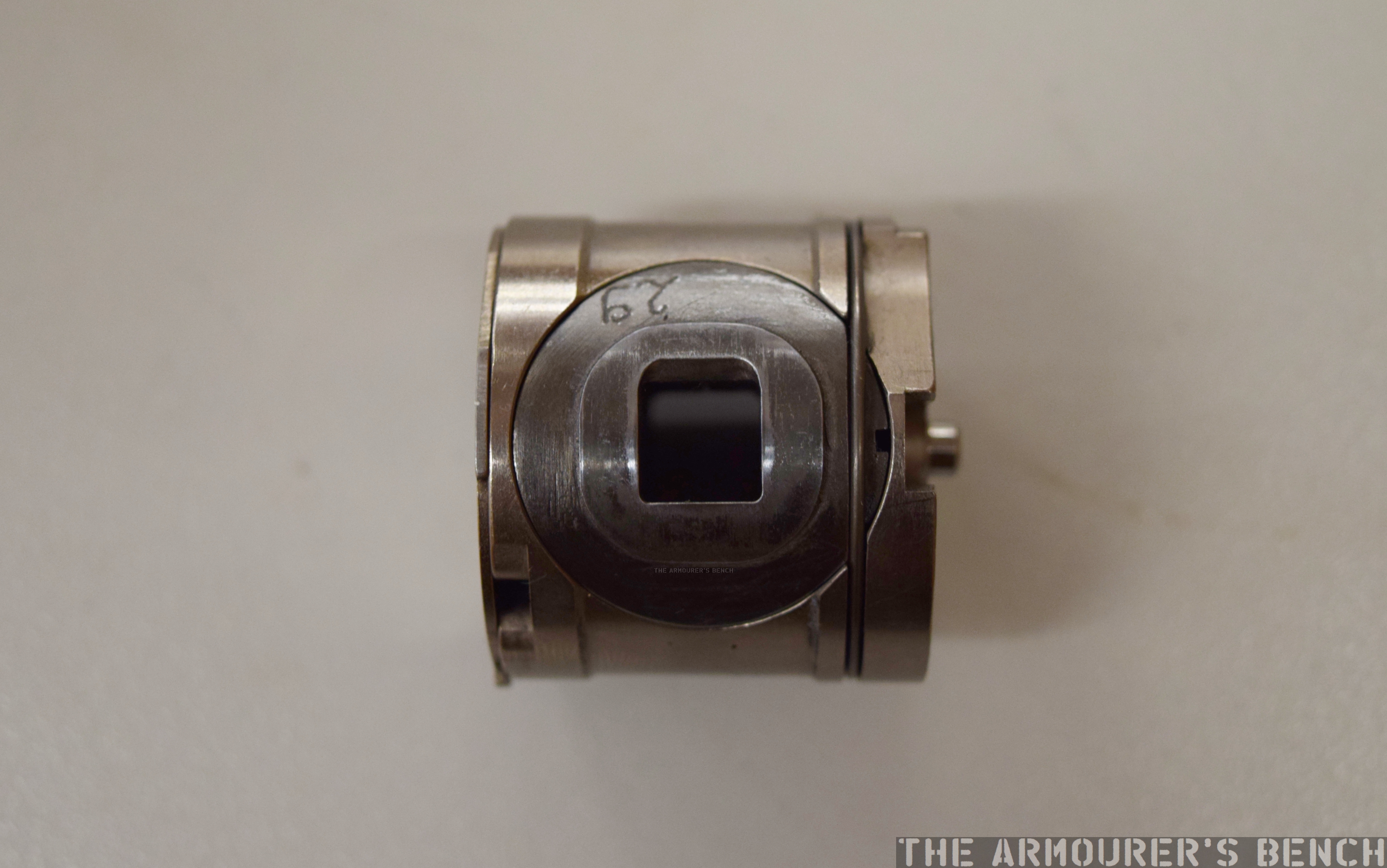
Top view of the breech cylinder (Matthew Moss)
A view of the square chamber which is a replaceable part which is held in the breech cylinder by a circular retaining spring – seen on the right (Matthew Moss)
The base of the breech cylinder with notches where the actuating gear interfaces (Matthew Moss)
Here are some close ups of the various parts of the action:
A close up of the rifle’s spur gear – which gives the G11 its almost clockwork appearance (Matthew Moss)
Another close up of the underside of the action (Matthew Moss)
Close up of the end of the barrel, with the square outline of the breech chamber visible – the G11’s caseless ammunition was rectangular but the projectile was round in diameter (Matthew Moss)
Another shot of the rear of the action showing the striker / firing pin assembly and spring (Matthew Moss)
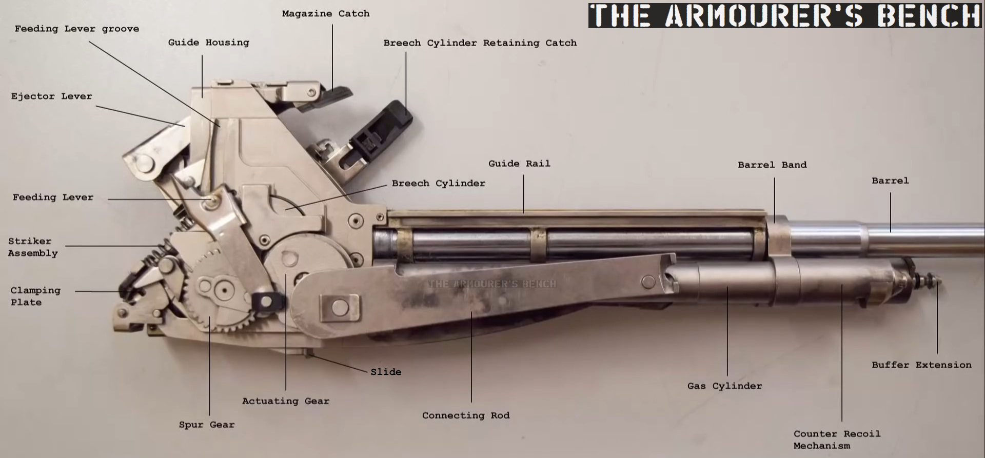
According to the 1989 armourer’s manual, provided for the ACR trials, the G11 is made up of a total of nearly 450 individual parts. 144 of those make up the G11’s breech assembly.
With the breech and barrel assembly removed from the centre assembly here’s a diagram I put together showing most of the component parts of the G11’s action:
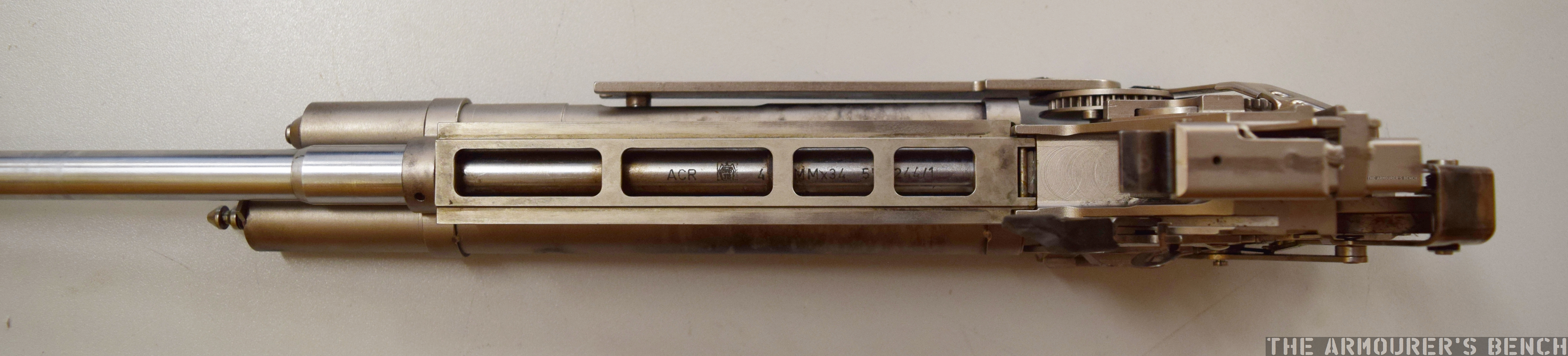
Next lets take a look at the G11’s barrel assembly with its recoil management system and gas piston:
A bird’s eye view of the G11’s breech and barrel assembly, note the barrel markings (Matthew Moss)
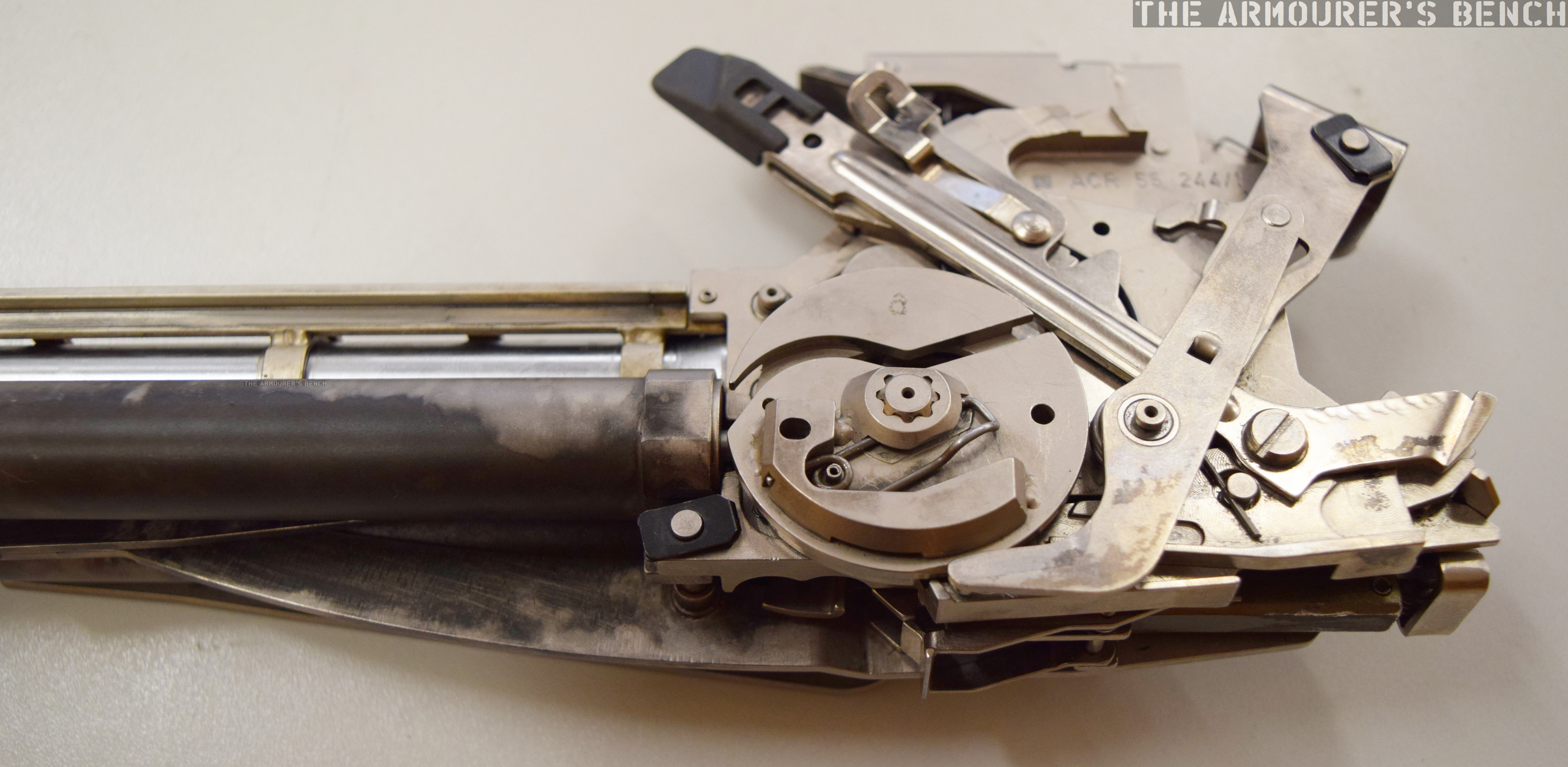
A side view of the breech with the cylinder and control disk in position (Matthew Moss)
A view of the housing of the recoil mitigation system, on the other side is the gas piston system (Matthew Moss)
Finally, here’s a photo of the G11 broken down into its major component assemblies: magazine, forend, centre assembly breech & barrel assembly and butt stock:
G11 field stripped (Matthew Moss)
If you enjoyed the video and this article please consider supporting our work here.
Bibliography
HK G11- ACR. Armourer’s Manual for Maintenance of Repair of Rifle, 4.92mm, ACR, March 1989 (source)
Held in the collection of the Cody Firearms Museum (CFM), at the Buffalo Bill Centre of the West, is a most intriguing Cold War submachine gun. The weapon came from the collection of the old Winchester Firearms Museum, which the CFM inherited, it is not a test & evaluation weapon made by another company but a submachine gun designed and developed by Winchester. Those who know their Winchester history will know the company had no prior background in submachine gun design, instead being best known for their rifles and shotguns.
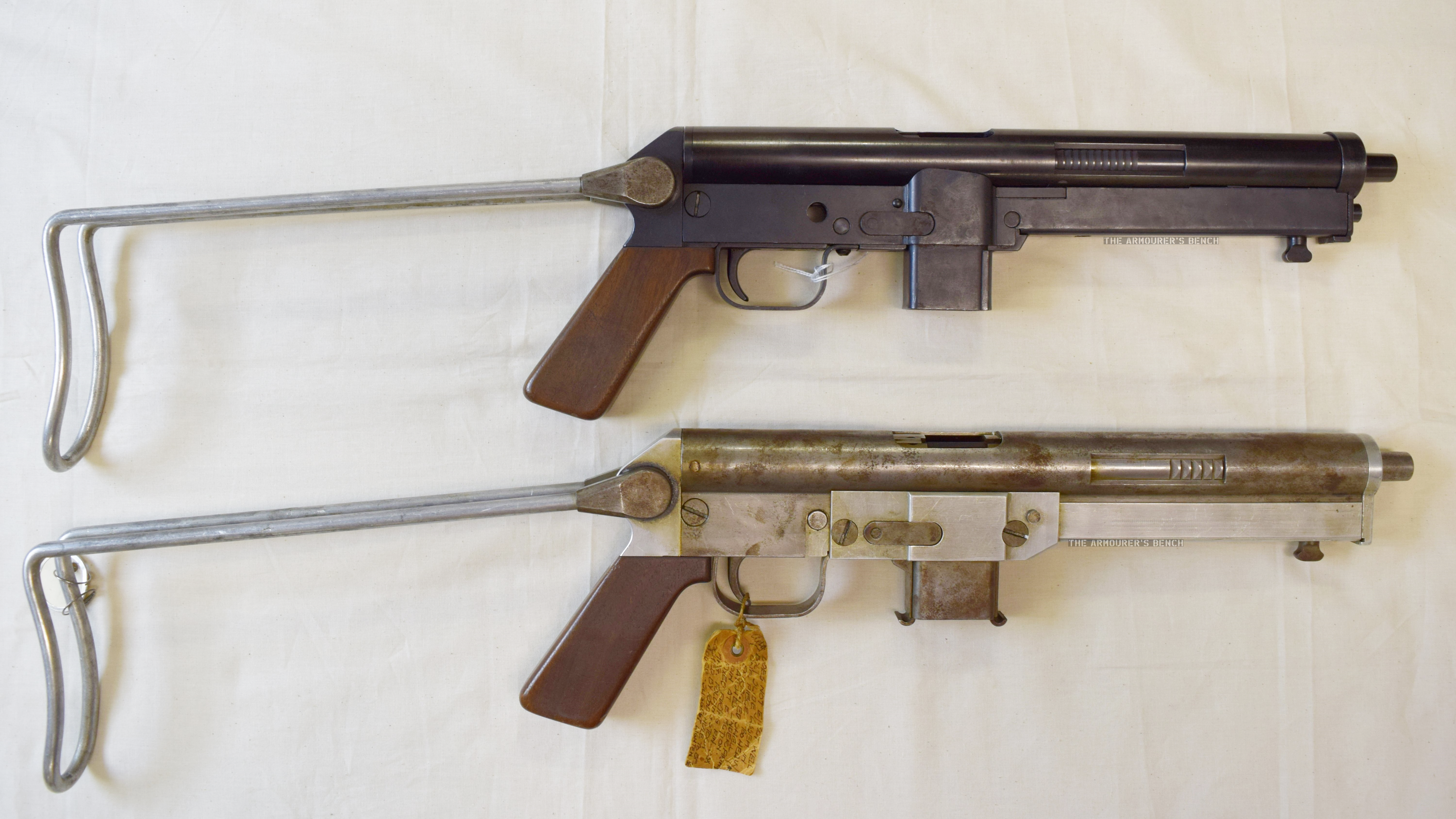
Left side profile view of the N4 and N2 Winchester submachine gun prototypes with their stocks folded (Matthew Moss)
Very little is known about Winchester’s submachine gun project, but two prototype examples survive, an early ‘in the white’ model labelled ‘N2’ and another which Herbert Houze, the CFM’s former curator, designated ‘N4’ . The documentary evidence for the Winchester submachine guns is sparse, amounting to just entries in the Winchester Museum’s inventory and a faded battered item tag attached to N2. A confusing element is that the inventory simply refers to the two prototypes as N-1 and N-2, with no mention of an N4.
There is also believed to be original engineering drawings housed in the Winchester Archival collection, currently held by the McCracken Research Library, but searches by myself and library staff have been unable to locate these.
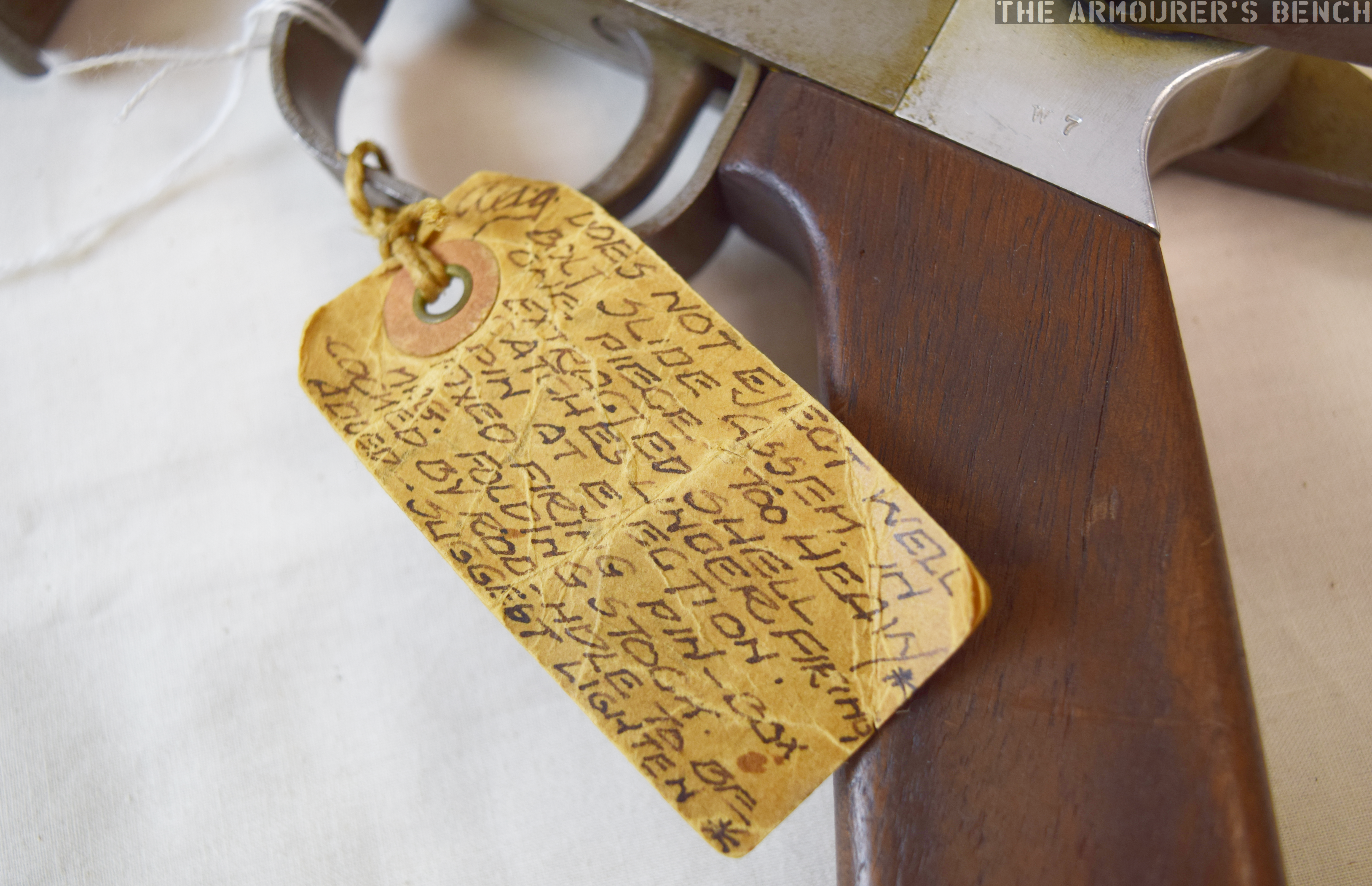
It is unclear if the tag from N2 is contemporary, perhaps added when the gun was handed over to Winchester’s museum, or if it was added later. In under 100 words it give us a short potted history of the N2 itself and the company’s programme to develop a submachine gun.
Close up of the N2’s item tag detailing the gun & program’s history (Matthew Moss)
Houze suggests the development programme began in 1955 and the tag attached the N2 suggests that development ceased in 1957, whether this is solely for that gun or the entire programme is unclear. This would make Winchester’s weapon a contemporary of the famous Israeli UZI.
The tag describes the N2 as a 9mm blowback ‘NATO Burp Gun’, followed by the name A.A. Arnold, a Winchester engineer perhaps best known for writing a series of manuals for Winchester firearms, followed by ‘dropped Dec ’57’. In his 1994 book, Winchester Repeating Arms Company: Its History & Development from 1865 to 1981, Houze suggests that the weapons were designed by A.A. Arnold and Melvin M. Johnson in 1955, for possible adoption by NATO. The association with NATO might also be the origins of the ‘N’ prefix. I have been unable to find any published patents attributed to Arnold, Johnson or the company relating to the experimental submachine gun.
I contacted NATO’s Archives who advised that they were unable to find any reference or documentation relating to a direct NATO submachine gun requirement. Another possibility is that the weapon was developed to market more broadly to NATO member nations. The submachine gun market at this time in Europe, however, was already saturated by both wartime surplus and a new generation of guns, including the Sterling, the UZI, the Madsen M50, and the Carl Gustav m/45.
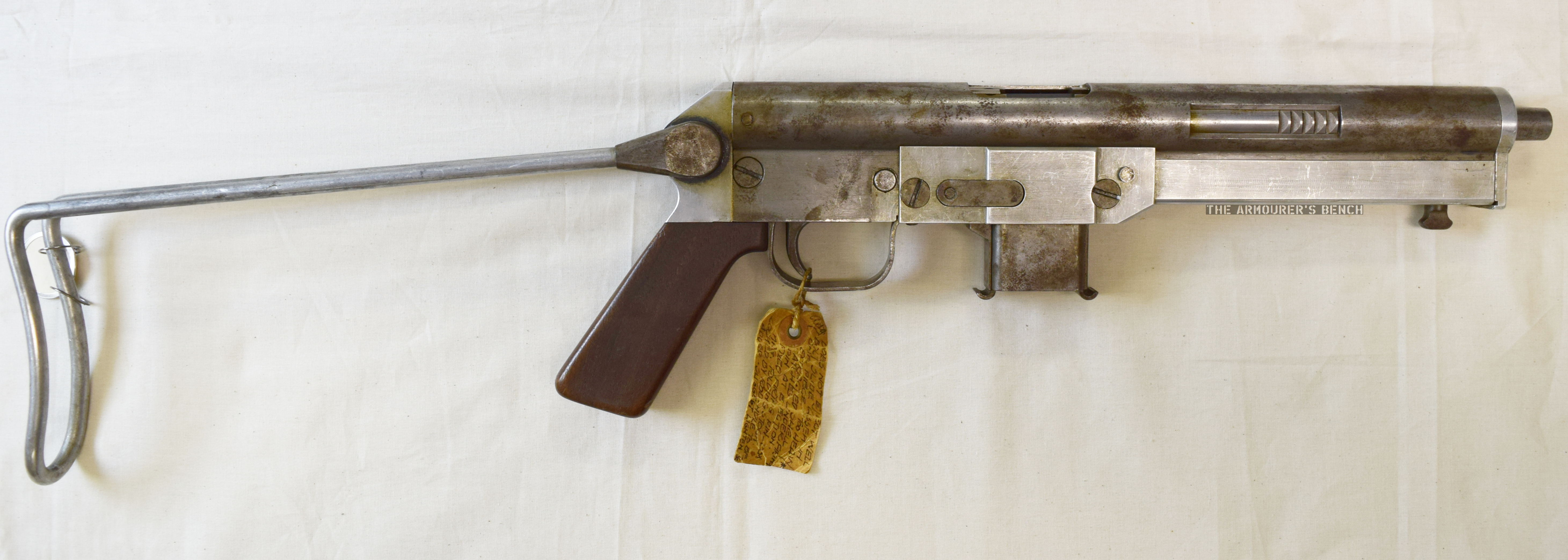
Right side profile view of the N2 ‘in-the-white’ prototype with its stock deployed (Matthew Moss)
The reverse of the N2’s label documents the prototype weapon’s reliability and feeding problems. The tag states that the N2 did “not eject well” and that the bolt slide assembly was too heavy. It also highlights failures to cycle properly with extracted cartridge cases catching under the firing pin. The label then gives a brief description of some of the N2’s features: “fixed firing pin, 33x Mag. Folding stock.” Interestingly, it also notes that the weapon would be cocked by a rod – the hole for which had not yet been added. The tag ends with a suggestion that the heavy one piece bolt assembly should be lightened.
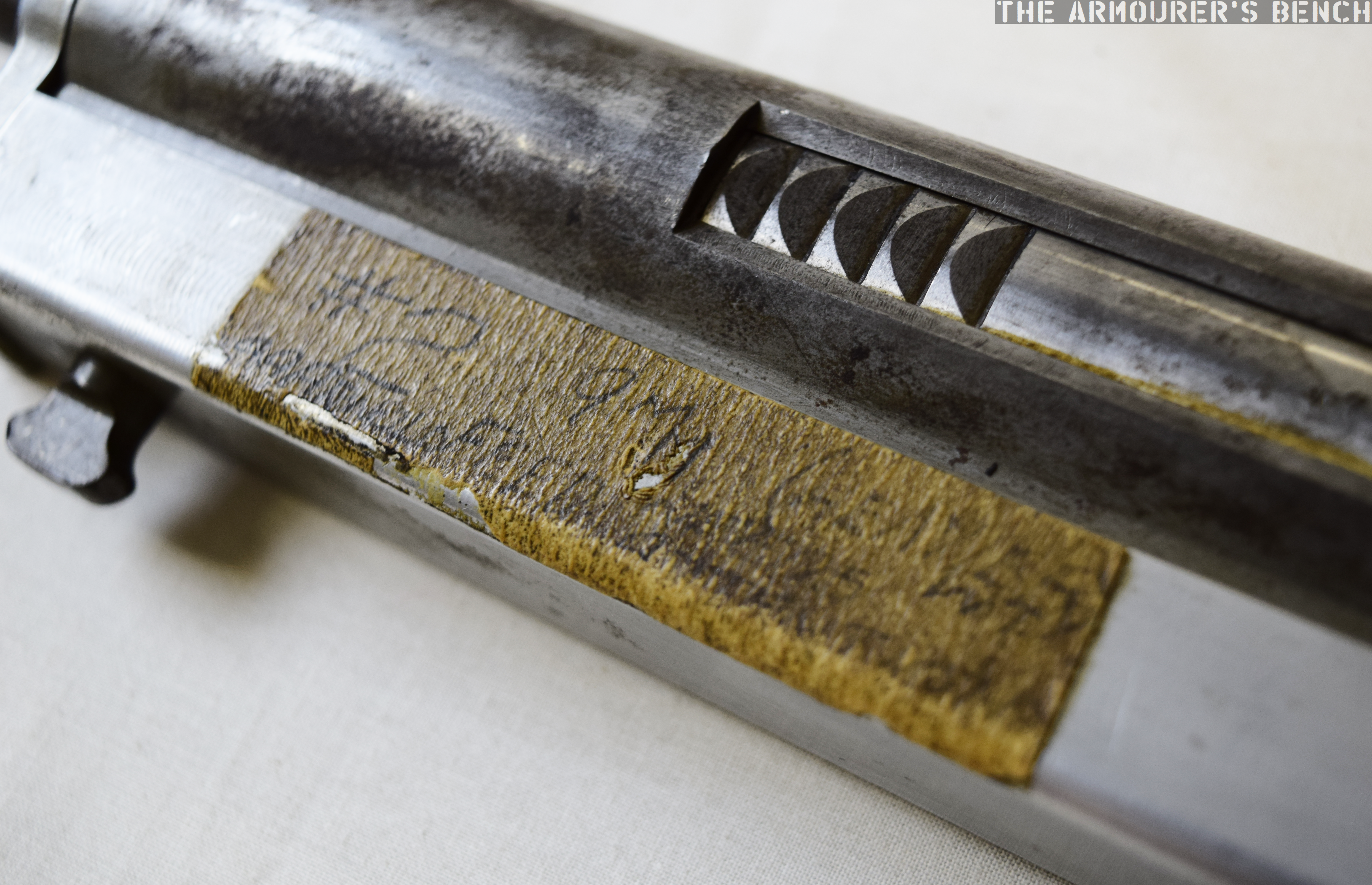
Close up of the N2’s difficult to decipher tape note (Matthew Moss)
N2 itself also has a piece of masking tape, on the recoil spring assembly cover, with its serial number and calibre written on it, along with A.A. Arnold’s name and some words that are too difficult to make out, but include ‘feed’.
Houze has also suggested that Melvin Johnson, designer of the Johnson rifle and light machine gun who joined Winchester as a designer and adviser in the early 1950s for a short time, and Stefan Janson, designer of the Brtish E.M.2 bullpup and subsequent Winchester engineer, both worked on the project. However, I have been unable to find any documentary evidence of their involvement.
Examining the N2:
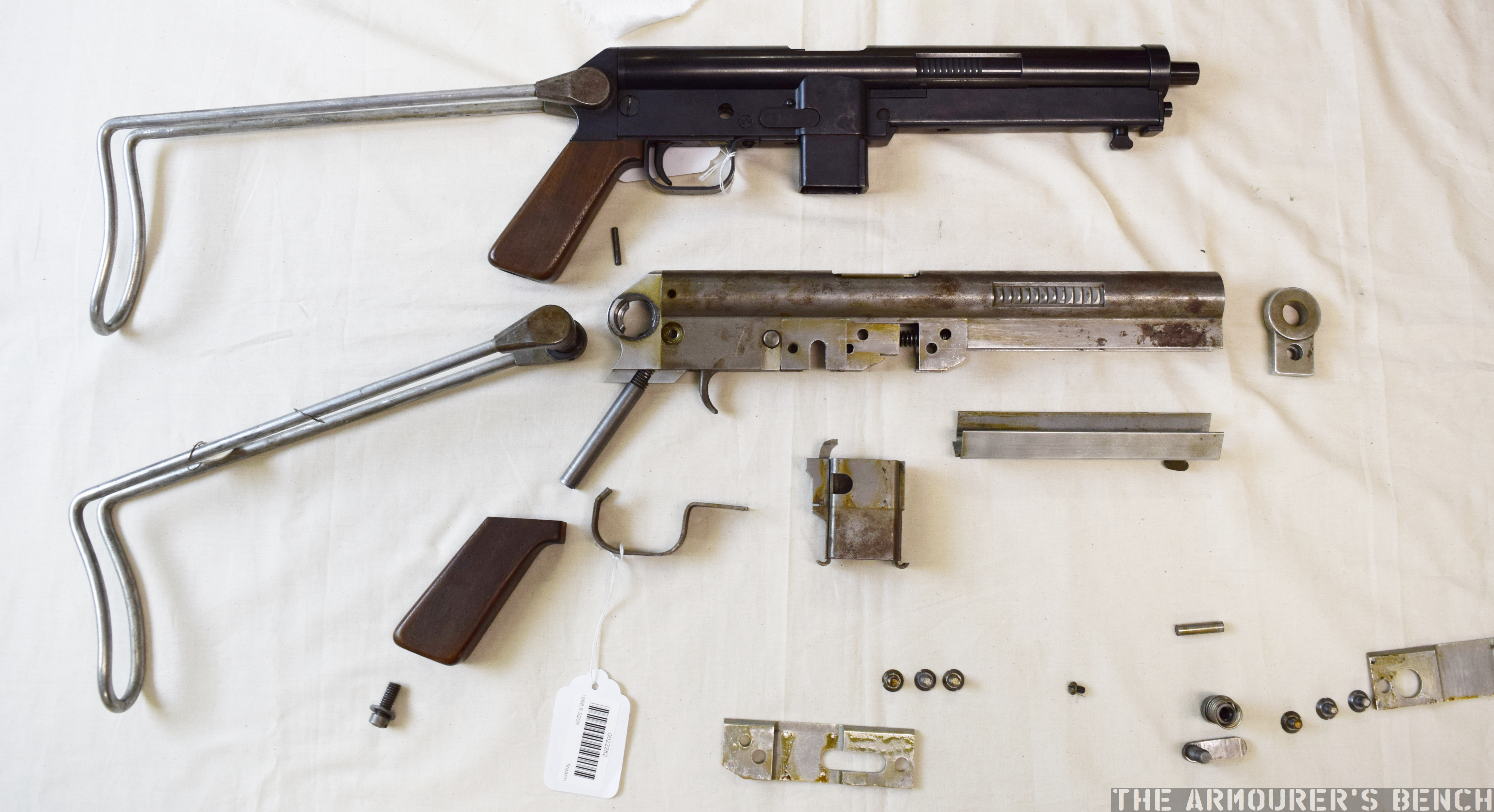
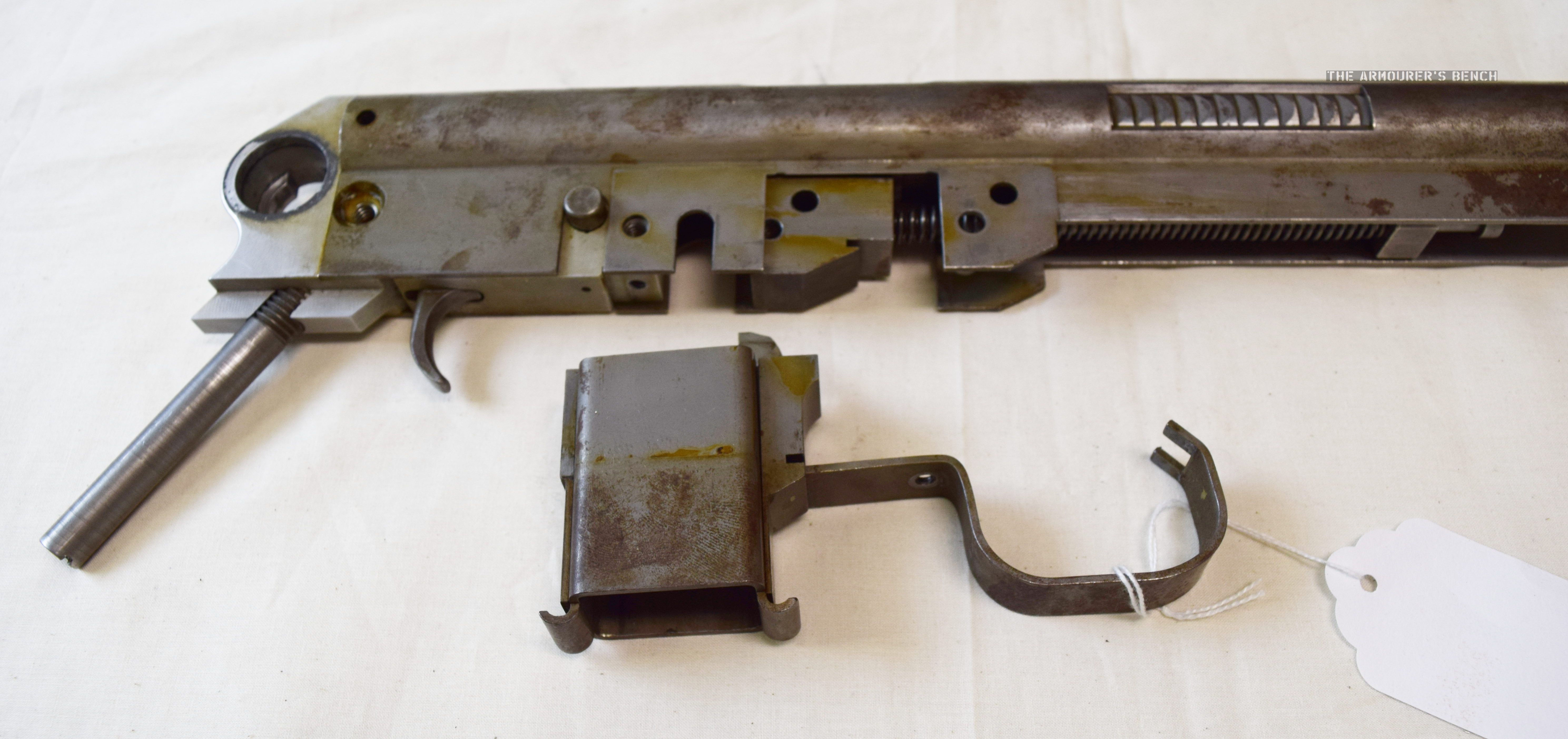
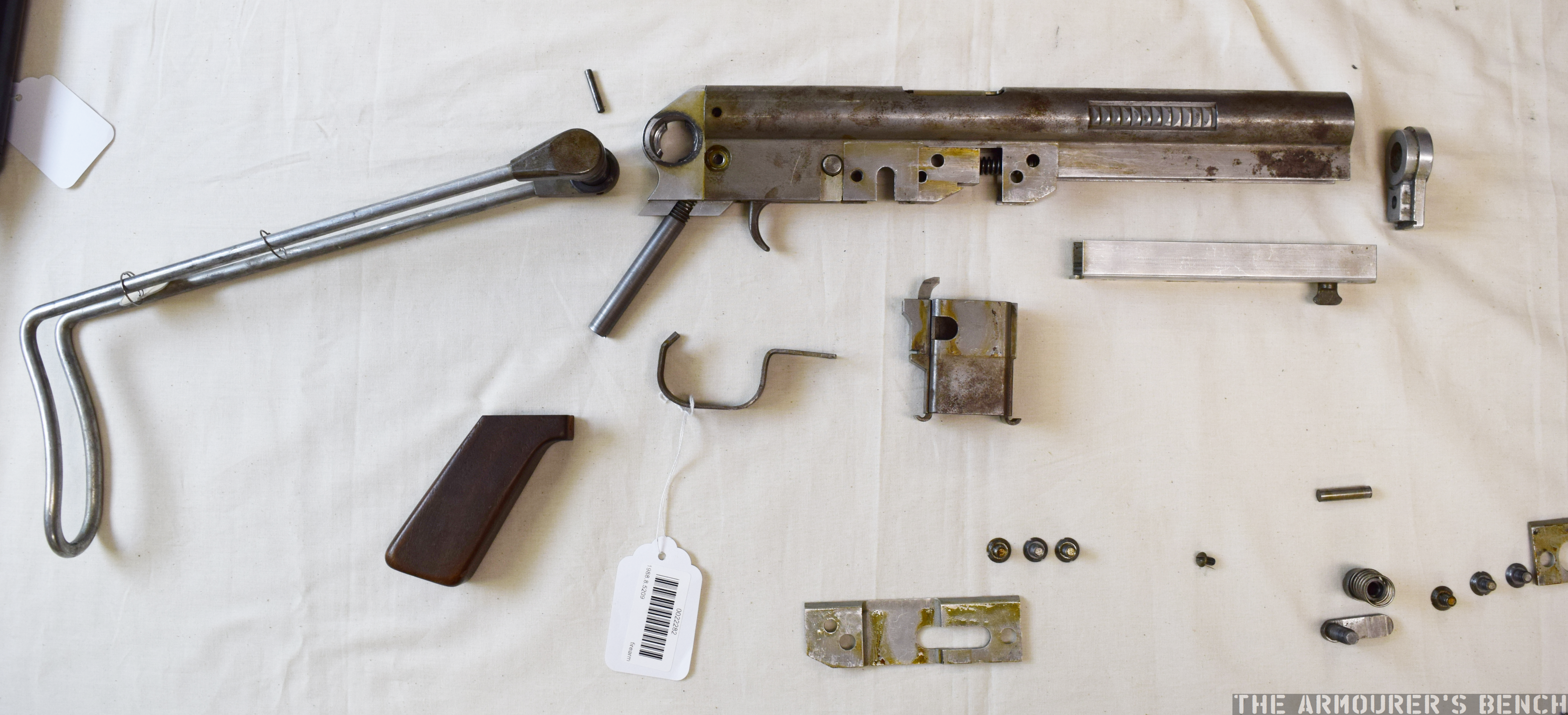
Winchester N4 and disassembled N2 prototype (Matthew Moss)
We can learn a lot from hands on examination of the two Winchester ‘N’ prototypes. Examining N2 we find that the receiver is made up of a piece of shaped sheet metal with a rounded upper half containing the barrel, bolt and cutouts for the grip points on the bolt assembly that allow charging. The bolt assembly rides over the rear portion of the barrel and projects back into the receiver. The lower section of the stamped receiver is rectangular and has a cut out for a separate magazine housing and fire control mechanism consisting of a trigger and push through safety – which we did not remove during disassembly. The N4 is missing its safety.
Close up of the N2’s magazine housing and trigger guard, note also the trunion freed from the receiver (Matthew Moss)
In the N2, the magazine housing is held in place by the stamped metal trigger guard which rocks into a notch behind the trigger and at the front interfaces with a notch in the magazine housing which has to be placed in the receiver at the same time, both are then held in place by a screw. This was changed in the later ‘N4’ with the trigger guard as a separate independent piece.
Winchester N2 Prototype Reassembly:
The side plates, muzzle end cap and recoil spring assembly cover all made from Aluminium – ostensibly to reduce weight. The submachine gun prototypes both use a pinch cocking method similar to that seen in the earlier British BSA WELGUN developed during WWII. The recoil spring proved to be too strong to cock easily, the addition of ‘rod’ cocking handle is suggested on the N2’s tag. The blued, later N4 prototype, however, is still lacking a conventional cocking handle. The pinch cocking method is not ergonomic, the user’s fingers could easily be caught by reciprocating bolt in charging cut outs in the receiver.
The N2 prototype disassembled, sadly we were unable to free the bolt from the receiver (Matthew Moss)
Another ergonomic consideration is the Winchester’s submachine gun’s unusually swept back pistol grip angle, the angle of the forward grip made by stock when folded is also similarly angled. Both the weapons have a push though safety selector just above the trigger (likely safe & fully automatic, but could not check as gun unable/difficult to cycle the prototypes easily). The weapon likely fed from a double stack, single feed magazine – either of an similar pattern to the MP40 or proprietary. The N4 seen in Houze’s 1994 book is shown with an MP40 magazine. UZI magazines fit the weapon but don’t lock into place.
The basic design does not change substantially between the prototypes with the control configuration, folding wire stock, pistol grip angle and magazine housing dimensions remaining the same. The N4, however, differs from the earlier prototype in a number of respects. The N4’s nose cap now fits over the rounded half of the receiver, rather than sitting flush and the cut outs in the upper receiver to access the bolt assembly for charging have been moved back slightly.
Right side view of the N4 blued prototype, note the half cocked bolt and the narrower grip serrations on the bolt assembly. Note also the intersection points of the recoil spring assembly cover and the upper receiver (Matthew Moss)
The later N4 model has pins in place of some of the screws used on the N2. The side plates have been replaced by a one-piece recoil spring assembly cover which projects back further over the magazine housing to the rear of the receiver. The most fundamental difference between the two is that it appears that the front part of the N4’s receiver has been significantly altered with the lower receiver at the front of the gun removed. It appears to have been replaced by the recoil spring assembly cover which appears to slot into the receiver. Sadly, we didn’t have time to disassemble the N4 to examine this.
The N4’s bolt assembly also has more serrations, in a slightly different orientation, on its bolt assembly gripping area, but still no charging handle as recommended on the N2’s tag. The ejection port on the blued prototype is also at a position closer to 12 o’clock when compared to the N2s.
Right side profile view of the two prototypes with their stocks deployed (Matthew Moss)
The N2 has a metal trunnion block, that the recoil spring guide rod screws into, this is held in place within the receiver by a cross pin. The bolt appears to be removed through the rear of the receiver once the stock assmbly/end cap is removed and the bolt assembly freed.
The folding stock was retained by spring tension of the wire metal stock against a wingnut-shaped catch that is riveted onto the recoil spring assembly cover. The stock is locked by a spring loaded push button system similar to the MP40s, this is not particularly sturdy. The shape of the wire stock itself is reminiscent of the US M3. When folded the butt of the wire stock acts as a front grip, the retention of the stock is surprisingly strong and stable.
Intriguingly, the Winchester Museum inventory notes that the guns are designated the N-1 and N-2, with an additional wooden model of the ‘Nato Burp Gun’ being transferred along with a box of duplicate parts in steel for the N2’s aluminium parts.
If you enjoyed the videos and this article please consider supporting our work here.
Winchester Repeating Arms Company: Its History & Development from 1865 to 1981, H. Houze (1994)
My thanks to the Cody Firearms Museum at the Buffalo Bill Center of the West for allowing me to examine and film the Winchester submachine gun prototypes. Special thanks to the CFM’s assistant curator Danny Michael for helping disassemble the N2.
All photographs taken by Matthew Moss, courtesy of the CFM & the Buffalo Bill Center of the West. Please do not reproduce photographs without permission or credit.
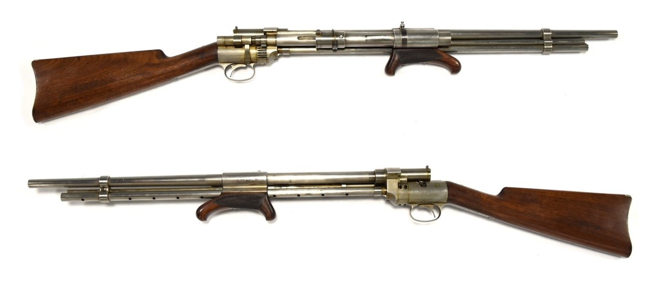
Today we’re examining an intriguing firearm with a fascinating history. It is difficult to understate the potential importance of the Curtis Rifle. Despite being designed in Britain in the 1860s the firearm gained more notoriety when it was offered as evidence in a legal battle between the Winchester Repeating Arms company and Francis Bannerman. What makes the firearm most noteworthy, however, is its fundamentally unconventional layout. Designed by William Joseph Curtis in the mid-1860s, it is arguably one of the earliest ‘bullpups’ and almost certainly the first repeating bullpup.
William Curtis’ 1866 ‘bullpup’ rifle, built in 1895 by Winchester (Photo by Matthew Moss, courtesy of the Cody Firearms Museum)
For the purpose of this article it would be wise to first define what a bullpup actually is. It can be defined as a weapon with a somewhat unconventional layout which places the action and magazine behind the weapon’s trigger group. This has the benefit of maintaining a conventional rifle’s barrel length while making the overall length of the rifle more compact.
Bullpup rifles became popular with a number of militaries around the world during the 1970s and 1980s – namely the Austrian Steyr AUG, the French FAMAS and the British SA80, and more recently with rifles from China and Singapore as well as the Tavor series of rifles from Israel.
Thorneycroft, Farquhar and Hill’s 1905 carbine patent (source)
The bullpup, however, dates back much further with some argument to be made for the first firearms to utilise the concept being 19th century percussion target shooting rifles. The earliest military bullpups date to the beginning of the 20thth century, these include a rifles designed by Samuel McClean, the initial designer of the Lewis Gun, patented in 1896 (US #723706), by Major Philip Godsal (US #808282) and a carbine developed by James Baird Thorneycroft in 1901. Thorneycroft subsequently worked with Moubray Gore Farquhar and Arthur Henry Hill to patent a refined version of the carbine in 1905 (US #827893). While the Thorneycroft was tested by the British army it was rejected due to ergonomic and reliability shortcomings.
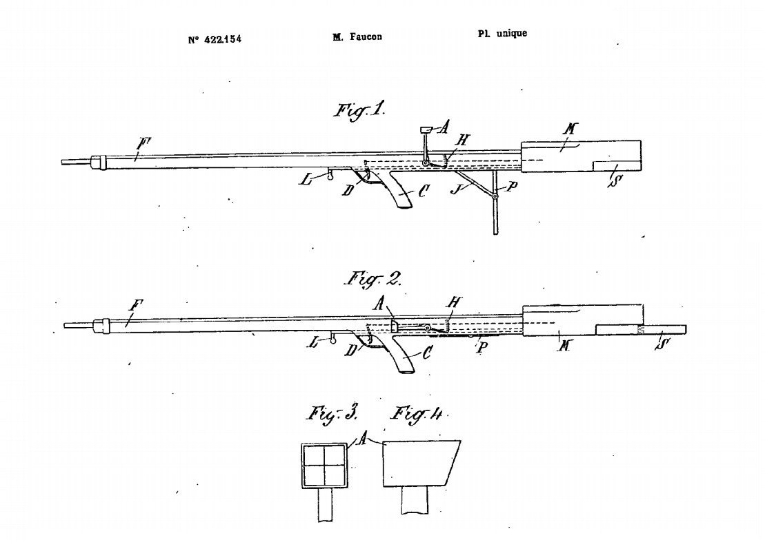
In 1908 Lieutenant-Colonel Armand-Frédéric Faucon of the Troupes Coloniales (French Colonial Infantry) began developing what he termed a ‘Fusil Équilibré’ or balanced rifle. Faucon patented his concept in France in 1911 (FR #422154) and continued to work on the balanced rifle during World War One, utilising a Meunier A5 semi-automatic rifle in working prototypes. The Faucon-Meunier rifle was tested in 1918 and 1920 but eventually rejected. It would be nearly 45 yeas before the bullpup concept was revisited by a major power. Engineers working at the Royal Small Arms Factory at Enfield and at the British Armament Design Department in the 1940s began to develop designs based around the bullpup concept. (Some of these will hopefully be the focus of future videos!)
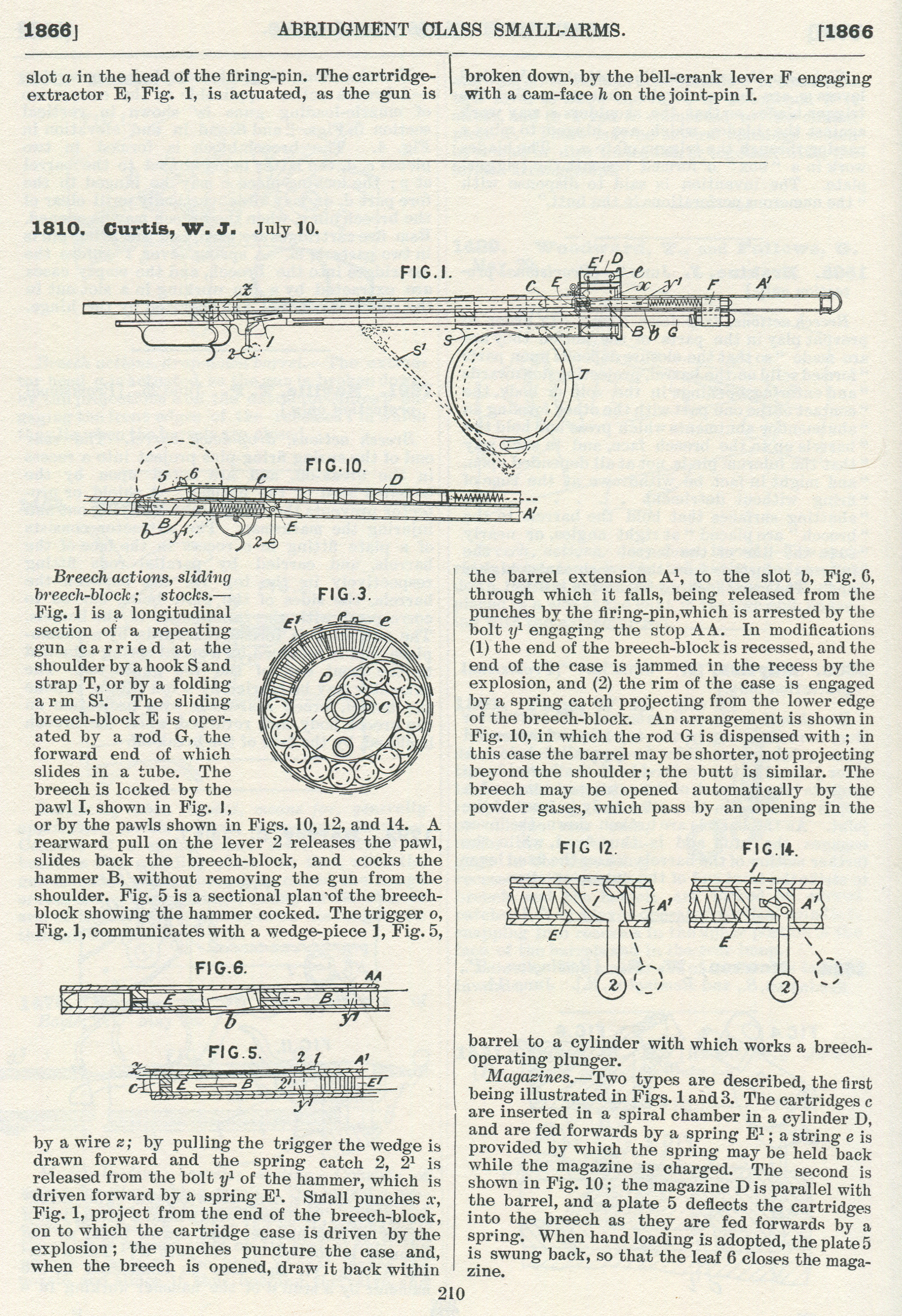
William Curtis’ design, however, predates all of these. Patented in Britain on 10th July, 1866, Curtis is listed by the London Gazette as a Civil Engineer. His design is unlike anything that had been seen before. Based on a slide-action with a drum magazine, it was placed over the shoulder – much like a modern shoulder-fired anti-tank weapon.
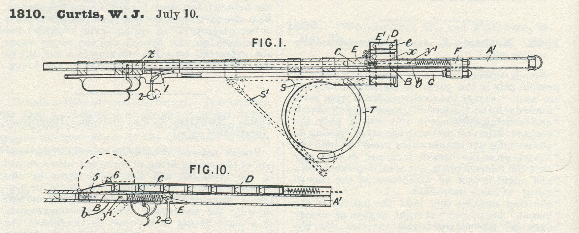
William Joseph Curtis’ July 1866 patent for ‘Breech actions, sliding breech-block & stocks’ (courtesy of Research Press)
Curtis’ rifle is probably the very first bullpup magazine rifle, one of the earliest to have a drum magazine (an Italian, Marco Antonio Francois Mennons, patented an earlier design for a drum magazine in March 1862, GB #637) and also an early striker-fired design. Clearly a design well ahead of its time and radically unconventional.
This unconventional gun’s designer was born in Islington, London in 1802, as a civil engineer he worked on Britain’s rapidly growing railway network. He died in 1875, placing the development of his rifle nearer the end of his life. With hindsight Curtis’ design clearly had revolutionary potential but it appears that his concept was never taken up. It appears that he only patented his design in the United Kingdom. If not for a corporate lawsuit on another continent, decades later, then it is possible Curtis’ design, like so many others, would have slipped into historical obscurity.
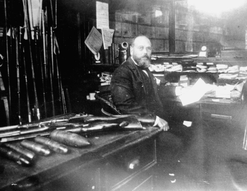
Francis Bannerman vs. the Winchester Repeating Arms Company
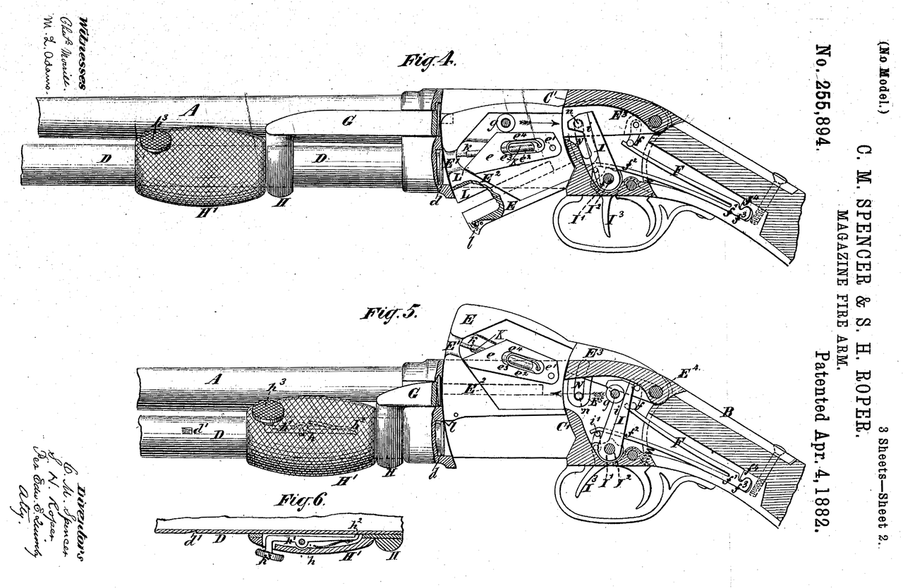
In 1890, Francis Bannerman VI, a successful entrepreneur specialising in junk, scrap and later surplus, purchased the Spencer Arms Company and the rights to their patents. The company had been founded by Christopher Miner Spencer, designer of the Spencer Rifle, they produced the first commercially successful slide or pump-action shotgun. This pump action shotgun was designed by Spencer and Sylvester H. Roper and patented in April, 1882 (US #255894). Bannerman continued producing the shotgun as the Bannerman Model 1890, however, in 1893 the Winchester Repeating Arms Company, introduced the John Browning-designed Model 1893 pump shotgun (US #441,390).
Spencer & Roper’s 1882 patent for their pump action shotgun (source)
In response in October 1894, Bannerman filed a law suit against the Winchester Repeating Arms Company claiming that the slide/pump actions used by Winchester’s Model 1890 and new Model 1893 shotgun infringed on the patents that he owned.
He called for the court to force Winchester to halt production and claimed $10,000 in damages and royalties for the sale of guns which he believed infringed his patent. Winchester temporarily halted production of the Model 1893, in the meantime Bannerman continued producing and improving his shotgun introducing the 1894 and 1896 models.
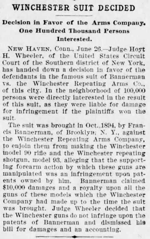
News report on the ruling of the Bannerman vs Winchester case from The Times (Philadelphia), 27th June, 1897
Various contemporary newspaper reports suggest between 100,000 and 500,000 people were directly interested in the case as ordinary owners were liable under the conditions of Bannerman’s suit.
Winchester dispatched George D. Seymour to Europe to scour the French and British patent archives for any patents for similar actions that had been filed there before those now owned by Bannerman. Winchester discovered four patents: three British and one French. The earliest of these was Alexander Bain’s patent of 1854. Two more patents held by Joseph Curtis and William Krutzsch were found, dating from 1866. The later French patent was filed by M.M. Magot in 1880. All of these designs, including the Curtis we are examining here, never progressed beyond the development stage and were largely forgotten until rediscovered by Winchester.
Model of William Krutzsch’s pump action rifle (Photo by Nathaniel F, courtesy of Cody Firearms Museum)
Winchester claimed that these earlier designs invalidated Bannerman’s patent claims. To illustrate their defence Winchester decided to build working models of each of the designs, breathing life into long forgotten patent drawings. This must have been a major engineering task as the patent designs would not have had all the information needed to produce a working model.
In 1895-96 Winchester engineers, including T.C. Johnson, assembled working models of each of the designs to prove their viability. These were tested and Winchester’s lawyers took them into court and submitted them as evidence, even offering a firing demonstration. The court declined the demonstration and made its decision on June 27th 1897. Judge Hoyt H. Wheeler of the United States District Court for the Southern District of New York ruled in favour of Winchester and threw out Bannerman’s suit.
Winchester had produced some 34,000 Model 1893s before, in November 1897, they introduced the improved Model 1897 which proved to be hugely popular on both the civilian and military markets. Bannerman unveiled a final shotgun, the Model 1900, but production ended in the early 1900s.
Curtis’ Unconventional Design
Right side, rear quarter, view of the Winchester-made Curtis Rifle (Photo by Matthew Moss, courtesy of the Cody Firearms Museum)
Curtis’ design encapsulates a number of features which, in 1866, were unheard of and arguably revolutionary. Not only is it probably the first magazine-fed repeating bullpup but it also uses a drum magazine, something that would not see substantial military use until the First World War. It has a folding shoulder support or stock, uses a striker fired action and makes use of self-contained ammunition.
This slideshow requires JavaScript.
The Curtis’ rifle is placed over the top of the user’s shoulder with a folding leather strap which fits into the shoulder pocket. Curtis’ original patent also suggests a fixed hook and strap. The user then grasps the loop near the muzzle with their support hand and the trigger and bolt handle with their other hand. Novel, but not the most ergonomic of designs.
Illustration of how the Curtis Rifle was ‘shouldered’ (Courtesy of the Cody Firearms Museum)
The magazine appears to hold at least 13 or more rounds according to the available patent and Winchester’s engineering drawings. The magazine is fixed in place and rounds appear to have been fed into it through the loading/ejection port on the left side of the weapon. This would have also put spent cases being ejected right next to the user’s neck. Curtis’ patent explains that the magazine has a spring inside which has a length of string attached to the top of it which the user can pull back to depress it and allow cartridges to be loaded into the drum. The magazine has a single stack or loop of cartridges. Once loaded the string can be released, allowing the magazine spring to push rounds into the action.
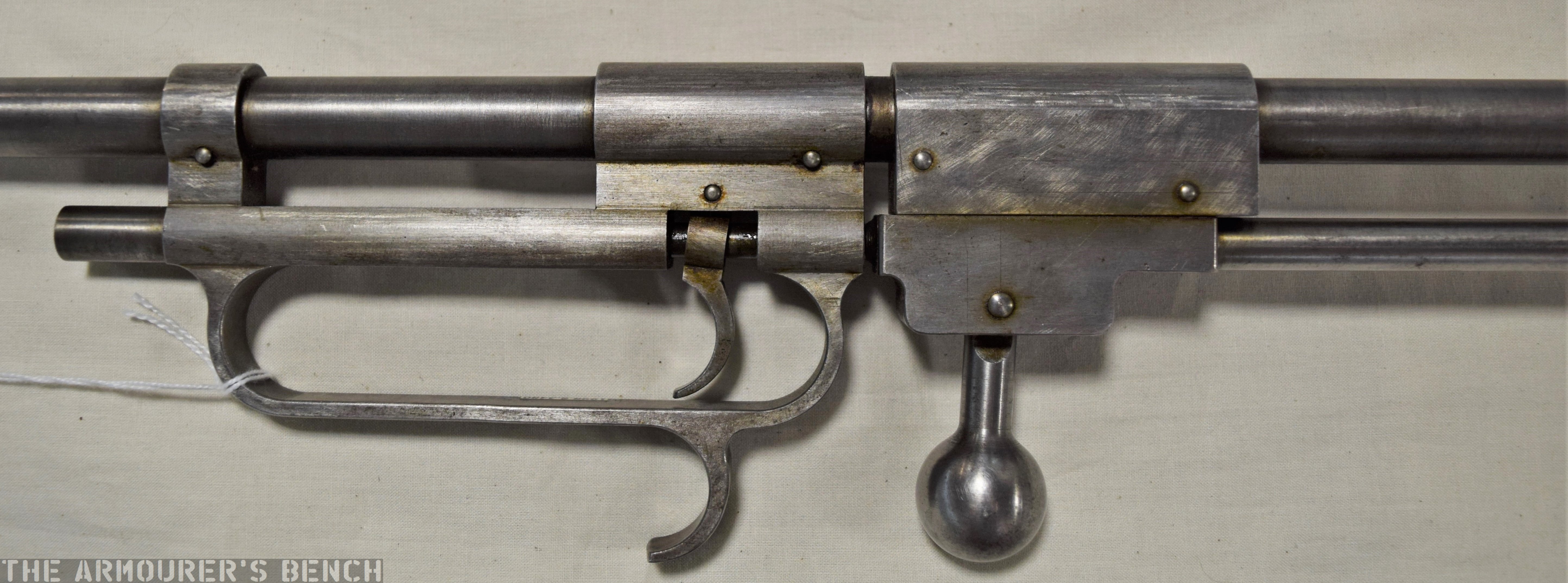
Close up of the left side of the Curtis’ trigger, bolt assembly and hand loop (Photo by Matthew Moss, courtesy of the Cody Firearms Museum)
The Curtis rifle’s action appears to lock at the front of the weapon with the bolt handle acting on a hinged, spring-loaded, locking piece or flapper which dropped into place when locked. To unlock the action the bolt handle was sharply pulled to the rear which pushed the locking piece out of engagement and unlocked the action allowing the operating rod to be cycled.
The weapon’s chamber appears to be just forward of the centre of the drum magazine with the striker assembly located behind it. To operate Curtis’ rifle the magazine was loaded and then the user had to unlock the action by pulling the bolt handle backwards. This then allowed the operating rod to be pulled backwards, like a pump action, which pushed the bolt and striker assembly to the rear, cocking the striker, the bolt handle was then returned forward and locked back into position. This chambered a round ready to be fired.
Close up of the Curtis’ brass drum magazine and loading/ejection port (Photo by Matthew Moss, courtesy of the Cody Firearms Museum)
The trigger at the front of the firearm is connected to the striker assembly by a long length of wire. When pulled the wire becomes taught and trips a sear to release the striker, firing the weapon.
Originally Curtis’ patent describes how ‘small punches’ on the bolt face would pierce the cartridge base during firing to enable the spent case to be extracted once the action was cycled. From Winchester’s engineering drawings, however, it appears they replaced this with a more reliable and conventional extractor at the 7 o’clock position of the bolt face.
Given that the weapon would have fired black powder cartridges it is unclear how well the rifle would have faired with sustained firing. The drum magazine would have been susceptible to jamming as a result of powder fouling. This, however, would not have been an issue for Winchester later version of the rifle.
Detail of Fig.1 & Fig.10 from Curtis’ 1866 patent (courtesy of Research Press)
But the Curtis has one more interesting surprise. The original 1866 patent also includes what might be one of the earliest descriptions of a gas operated firearm. One of the most fascinating sections of Curtis’ original patent details how the rifle might have been adapted for gas operation:
“An arrangement is shown in Fig.10, in which the rod G is dispensed with; in this case the barrel may be shorter, not projecting beyond the shoulder; the butt is similar. The breech may be opened automatically by the powder gases, which pass by an opening in the barrel to a cylinder with which works a breech operating plunger.”
Curtis does not go into further detail but he is clearly describing a piston-driven, gas operated system. The patent drawing also depicts an alternative tube magazine instead of the drum magazine.
It is unknown if Curtis ever put his theory to the test and developed his gas system idea further. It is tempting to wonder if, in 1895 when Winchester were assembling their model of the Curtis, if John Browning or William Mason, who were also developing their own gas operated systems at the time, were aware of Curtis’ idea from 30 years earlier. As such Curtis’, admittedly vague, gas system pre-dates the first patents on gas operation by just under 20 years.
If you enjoyed the video and this article please consider supporting our work here.
Specifications:
Action: Slide action
Calibre: .32 Winchester Centre Fire
Feed: ~12 round drum magazine
My thanks to the Cody Firearms Museum at the Buffalo Bill Center of the West for allowing me to examine and film the Curtis. Special thanks to the CFM’s assistant curator Danny Michael for making extra time to open up the case where the rifle Curtis is on display so we could examine it and for also sharing Winchester’s technical drawings and other records.
Thanks also to David Minshall of Research Press.co.uk for his assistance finding Curtis’ original British patent abridgement and to John Walter for digging up some additional information about Curtis’ life.
Bibliography:
‘Winchester Suit Decided’, The Times (Philadelphia), 27th June, 1897
‘Recollections of the Forming of the Pugsley & Winchester Gun Collections: A Talk Given by Mr. Edwin Pugsley at the New Haven Meeting of the AS of AC’, September, 1955.