By 1895 Winchester had been considering a slide-action rifle for some time, in 1882 William Mason had begun work on one (US Patent #278987) to counter Colt’s slide-action Lightning only to drop it. Finally in 1890, Winchester introduced a slide-action .22 calibre rifle developed by John Browning. The Model 1890 became extremely popular.
Between 1887 and 1895 Browning patented four slide-action rifle designs. The first of these, US patent #367336, was granted in July 1887, this was followed in 1888 by US patent #385238. In September 1890, the Browning brothers were granted US patent #436965, which along with the previous 1888 patent protected what became the Model 1890. Three years later Winchester introduced the Model 1893 pump action shotgun, that would eventually evolve into the famous Winchester Model 1897.
Right-side close up of the rifle with its action open (Matthew Moss)
Finally, April 1895, Browning filed a patent for a design for a .30 calibre rifle which was granted in September 1895 (US patent #545672) This patent covers the rifle we’re examining here. The rifle itself is a slide or pump action in long barrelled configuration which Winchester described as a ‘Musket’.
The September 1895 slide-action design was purchased by Winchester but like so many other Browning designs, it never entered production and Winchester purchased the design purely to secure it and prevent other rival manufacturers picking it up. Winchester instead went with a lever-action design, patented in November 1895 (US #549345), which became the famous Winchester Model 1895.
A left-side view of the rifle’s receiver with Browning’s patent overlaid (Matthew Moss)
The September 1895 slide or pump-action rifle design had a laterally camming locking breechblock. As we can see, externally Browning’s toolroom prototype looks somewhat similar to the contemporary Winchester Model 1895, with a single-stack integrated box magazine but with a pump sleeve rather than a lever.
An action-bar connects the slide/pump to the front of the breechblock/bolt carrieron the right-hand side of the rifle. The slide handle itself is made of a U-shaped piece of metal which wraps around the rifle’s forend. The slide has been roughly cross hatched to improve grip. There is a channel cut into the furniture for the action arm’s attachment point to travel. The slide is attached to the arm by a pair of screws.
A close up of the rifle’s slide/pump handle (Matthew Moss)
However, Browning developed this prototype to allow loading of the magazine from below rather than through the top of the receiver. He added a hinged floor plate, with a spring loaded follower, that allowed loose rounds to be dropped into the magazine and then closed.
As we open the magazine, hinging the cover plate down, we see the carrier flip down against the plate to allow loading. The rifle was designed to be loaded from below with the bolt forward.
Browning’s September 1895 patent (US Patent Office)
In the patent description Browning explained that his aim was to improve breech-loading box-magazine firearms by designing:
“…a simple, compact, strong, highly effective, and safe gun, containing comparatively few parts and constructed with particular reference to provision for charging the box-magazine with cartridges from the bottom of the frame of the arm while the breech-bolt is in its closed position, so that the arm may be charged without operating its action mechanism or disturbing the cartridge in the gun-barrel, if one is there.”
Browning’s September 1895 patent (US Patent Office)
From the original patent drawings we can see the flat spring which acted on the carrier running below the barrel, ahead of the magazine. Inside the magazine are a pair of what Browning refers to as ‘spring fingers’ these act on the cartridges inside the magazine and keep them properly aligned, seen here in Fig.7 of the patent. In Fig.8 we can see what Browning calls a ‘box-like guideway’ which guide the rims of the cartridges, “preventing the cartridges from being displaced while being fed upwards.”
The rifle’s breechblock locked into a recess in the left side of the receiver, tilting at an angle with the rear of the breechblock canting to the left. When the pump handle was pulled rearwards the breechblock cammed laterally to unlock the action, extracted and ejected any spent casing and when the slide/pump was returned forward a new cartridge was picked up from the magazine, chambered the breechblock locked again ready to fire. The rifle’s hammer was cocked by the rearward movement of the breechblock.
A left-side view of the rifle with its action open, note the complex machining on the rear of the breech bolt (Matthew Moss)
Externally, the slide-action’s receiver looks similar to that of the production Model 1895 but internally they are very different. The action is certainly less open than the Model 1895’s but the lateral locking mechanism is less robust. Additionally, with no lever, as in the Model 1895, the slide-action rifle lacks the safety mechanism which prevents the action from opening accidentally.
A view inside the open magazine with the floorplate hinged open (Matthew Moss)
The model is in the white and while externally the machining and tool work is very neat, inside the action we can see where the cuts in the receiver wall have been more crudely made. In terms of design, the slide-action prototype was certainly simpler and had fewer working parts than the Model 1895 lever-action.
Winchester purchased the .30 calibre slide-action design but never produced it, it is believed that only Browning’s prototype was built to prove the concept. The prototype was part of Winchester’s collection and may now be found at the Cody Firearms Museum.
Development of the XF-87 began at Curtiss-Wright in 1946, it would eventually be intended to be an all-weather interceptor. The Blackhawk was developed from an earlier ground attack, tactical bomber design, the XA-43. The Blackhawk was a response to the initial specification for a jet-powered night fighter, capable of speeds up to 530 mph, issued by the US Army Air Force in August 1945.
A number of companies responded including Bell Aircraft, Consolidated-Vultee, Douglas Aircraft, Northrop, Goodyear and Curtiss-Wright. The US Army Air Force down-selected Northrop’s design – then known as the N-24 and the Curtiss-Wright design- known as the Model 29A.
Curtiss-Wright XF-87 (US Air Force)
The XP-87 had a two-man crew seated side-by-side and was powered by two pairs of Westinghouse XJ34-WE-7 turbojet engines mounted on the wings. In comparison to the sleeker Northrop design, the Blackhawk was a slightly larger, bulkier and heavier aircraft with a straight wing profile. The XJ34-WE-7 turbojets only provided 12,000 lbf and Curtiss-Wright’s test pilot B. Lee Miller described performance in initial tests as sluggish. The Blackhawk’s armament was to consist of four 20mm cannons mounted in a nose turret.
The US Army Air Force designated the Curtiss-Wright jet the XP-87, while Northrop’s N-24 became the XP-89 and full-scale models of both were ordered.
The Curtis XP-87 (Curtiss-Wright, courtesy of Mark Lane)
In June 1948 the newly formed US Air Force re-designated fighters from P to F and the XP-87 became the XF-87 when prototypes were ordered. The XF-87 made its first flight in March 1948. During subsequent flight evaluations in October 1948, the Northrop XF-89 was found to be faster than the XF-87 and the US Navy’s XF3D (Douglas F3D Skyknight). While the Blackhawk was a capable and generally satisfactory aircraft it was deemed to be underpowered. It also reportedly suffered from buffeting at relatively slow speeds.
Walter Tydon’s patent for the Blackhawk’s landing gear (US Patent Office)
Evaluators disliked the Northrop and reportedly favoured the XF-87, however, one evaluating pilot likened its handling to a medium Bomber. An improved faster and more powerful Blackhawk was planned with J47 engines from General Electric. The fate of a second prototype is unclear and sources conflict. Most sources state that the XF-87 never had its armament fitted, however, photographic evidence clearly shows an aircraft, not with a turret, but with four nose mounted guns. This aircraft may be one of the airworthy prototypes or it could be a full-scale mock up built to show the USAAF during the selection process.
Despite the trials favouring the XF-89, the USAF initially ordered 57 F-87A fighters and 30 RF-87A reconnaissance aircraft from Curtiss-Wright in June 1948. Curtis-Wright and the USAF began a publicity campaign to unveil the new fighter, even appearing on the cover of an August edition of Aviation Week and in numerous other aviation publications, but the orders were abruptly cancelled in October 1948 and the USAF moved forward the development of the Northrop XF-89 instead. Check out our video on the F-89 Scorpion linked above.
The ‘F-87’ Blackhawk on the cover of Aviation Week (courtesy of Mark Lane)
The reason for this reversal of the decision is unclear. Only minor faults had been identified during testing and the more powerful J47 engines would have greatly increased the Blackhawk’s speed. The official reason for the cancellation was reportedly a disagreement on the price of a redesigned wing profile. According to his memoir, Walter Tydon, Curtiss-Wright’s chief engineer at the time, believed that some bad blood between Curtiss-Wright’s management and the then-President Harry S. Truman may have led the F-87 contract to be cancelled. Truman was Senator for Missouri from 1935 to 1945 and during that time Tydon believed he had come into conflict with the Curtiss-Wright’s management, perhaps regarding the company’s factory in St. Louis. Without substantial archival research it is difficult to verify either the official reason or Tydon’s theory.
Another potential reason for the cancellation was raised during the Congressional Hearings regarding the B-36 Program, Congressman Charles B. Deane noted that both Curtiss-Wright and Northrop had been informed that “unless they agreed to merge with Consolidated Vultee, business would be bad for them.” The testimony before the hearing notes that Curtiss-Wright were unenthusiastic about a potential merger and this might have been why the F-87 contract was cancelled. The Secretary of the Air Force denied this, however, stating that the cancellation was the result of “operating difficulties with the experimental model of the F-87, plus increasingly satisfactory operating data on competitive all-weather fighters.”
The XF-87 Blackhawk taking off (courtesy of Mark Lane)
Sadly, the prototype XF-87 Blackhawk’s was reportedly scrapped and photographs and footage of the initial flight testing of the Blackhawk is all we have left. The loss of the interceptor contract to Northrop led to the end of Curtiss-Wright’s aircraft production, with the Blackhawk being their last fighter design.
Special thanks to Mark Lane, the grandson of Walter Tydon, Curtiss-Wright’s chief engineer, for taking the time to discuss the Blackhawk and his grandfather’s role in its design.
In May 1946, George Patchett patented a new curved magazine which would become one of the Sterling’s most recognisable features. It addressed some of the serious shortcomings of the STEN’s magazine.
George Patchett’s machine carbine, Which later that came to be known as the Sterling, had been initially designed to use the standard STEN magazine. This makes complete sense as not only was the STEN’s magazine readily available but it stood to reason that the British Army would prefer to retain the large number of magazines it already had in stores.
A Sterling L2A3 with a disassembled Sterling commercial-pattern magazine (Matthew Moss)
The STEN’s magazine is, however, the gun’s weakest link. Its a double-stack, single feed 32-round magazine was difficult to load and could feed unreliably when not looked after. The Patchett prototype performed well during initial testing in 1943, but later sand, mud and arctic testing of the Patchett against various other submachine guns highlighted the limitations of the STEN magazine – regardless of the weapon using it.
Patchett’s Original Toolroom prototype (Matthew Moss)
At some point in 1945, Patchett developed a series of new magazines, a 20-round ‘Patrol’ magazine, a 40-round ‘Standard’ magazine and a 60-round ‘Assault’ magazine. By late 1946, these had been superseded by a 35-round magazine designed to fit into the basic pouch of the British Army’s 1944 Pattern web equipment.
Patchett addressed the STEN magazine’s shortcomings by designing his magazine with a curve which allowed the slightly tapered 9×19mm rounds to feed more reliably. He also replaced the traditional magazine follower with a pair of rollers which minimised friction and allowed dust, grit and dirt to be rolled out of the way improving reliability. Patchett’s magazine was designed so it could be economically stamped from sheet metal and folded and spot welded into shape. It was also simple to disassemble for cleaning and requires no tools for disassembly.
George Patchett’s US patent for his roller magazine follower (US Patent Office)
By 1951 the magazine had been largely perfected but a trials report suggested that the magazine’s feed lips needed to be reinforced. Despite this the Sterling was said to be “better than all other weapons tested.” Following further development and testing the L2A1 Sterling submachine gun was eventually adopted in the summer of 1954. We will cover the development, adoption and service of the Sterling at a later date.
In 1952, Patchett added a pair of strengthening ribs to the inside of the magazine which also further reduced friction on the rollers. He also replaced the oval follower spring with a more efficient circular one with the ribs acting to hold it in place. The final production magazines held 34 rounds and were substantially easier to load than the earlier STEN’s.
Patchett’s US patent for his circular magazine spring held in position by the stamped magazine body (US Patent Office)
The L2A1/MkII, introduced in 1954, was the first Patchett to incorporate an angled magazine housing which improved feeding reliability from the Patchett’s patented curved, double stack, double feed magazine. The Sterling’s magazine housing was angled forward slightly at 82-degrees.
The magazines used by the British military differed from Patchett’s design. The British government, perhaps unwilling to purchase the rights to manufacture Patchett’s design, developed the ‘Magazine, L1A2’. Nearly two million of these were built at Mettoy, Rolls Razor, ROF Fazakerley and the Woolwich Royal Laboratories. The L1A2 magazine was slightly simpler to manufacture but retained Patchett’s roller follower while the magazine’s body was made from two, rather than four, pieces of stamped steel and electrically welded together. The government-designed magazine is 5cm (2 inches) longer than Sterling’s magazines.
disassembled Sterling commercial-pattern magazine (Matthew Moss)Rear edge of the magazine, with Sterling factory markings (Matthew Moss)
The example magazine seen above and in the accompanying video is Sterling-made and is marked with the company name and patent numbers. We can see the folded sheet metal construction and the overlaps at the rear of the magazine body.
Patchett’s patented-roller follower and circular amazing spring (Matthew Moss)
When Canada adopted the C1, a modified version of the Sterling, they dispensed with Patchett’s roller system and designed their own magazine which held 30, rather than 34 rounds, but could be used in all Sterling-pattern guns.
On the front of the magazine is an over-insertion stop built into the edge of the magazine body, at the rear is another magazine stop with a flat spring which limits rattle and helps properly align the magazine in the breech for optimal feeding.
Today, were taking a look at a Winchester prototype developed in the mid-1860s, a period when Winchester was seeking to build on the success of the 1860 Henry Rifle and place the company on a firm financial footing. Oliver Winchester had taken control of the New Haven Arms company before the Civil War and while for a time it had been known as the Henry Repeating Arms Company he eventually sought to put his stamp on the company, renaming it Winchester Arms Company in 1866. At the same time he decided to focus the company’s energies on winning military contracts around the world.
Left & right profiles of King’s prototype musket (Matthew Moss)
This developmental prototype is in the ‘musket’ configuration: with a longer barrel, a bayonet lug and a wooden forend. The prototype represents one of the many developmental steps towards what would become the Model 1866. It has a number of interesting features – a steel, rather than brass, receiver and a hinged loading port developed by Nelson King, Winchester’s superintendent between 1866 and 1875.
The rifle itself was built by Luke Wheelock, Winchester’s model room mechanic and a designer in his own right who would go onto develop his own rifle designs for Winchester.
King’s 1866 patent (US Patent Office)
The rifle is 54.5 inches long, with a 33.75 inch barrel. Believed to have been built in 1866, it is chambered for a .45 calibre rimfire round. King patented his loading port in May 1866. He described how the port worked:
“Through one of the plates S (preferring that one upon the right-hand side) I form an opening, 0, as denoted by broken lines, Fig. 1, and also seen in section, Fig. 7. This opening is formed so as to communicate through the frame directly to the chamber E in the carrier block, as seen in Fig. 3. Through this opening, and while the carrier-block is down and all parts of the arm in a state of rest, insert the cartridges, point first, through the said opening in the plate S into the chamber E the second cartridge pressing the first into the magazine, and so on with each successive cartridge until the magazine is filled, or until the requisite number has been inserted therein, the follower G being pressed up before the entering cartridges. In the rear of the chamber E2 the frame forms a shoulder to prevent the cartridges from being forced out through the opening in the plate S3 is a cover for closing the opening in the plate S3 and is hinged thereto, as seen in Figs. 1 and 7, the hinge being provided with a spring,a1, the tendency of which is to open the cover C. A spring-catch, d, (see Fig. 1,) secures the cover when closed, so that by pressing upon the said catch the cover will fly open. After the requisite number of cartridges have been placed within the magazine, close the cover, as seen in Figs. 1 and 2.”
A close up of the hinged loading gate (Matthew Moss)
To paraphrase: ammunition can be loaded through the opening in one of the receiver side plate when the carrier block is down, insert the cartridges through the opening, pressing the first into the magazine and so on until the magazine is filled… a cover for closing the opening is hinged to the receiver side plate. A spring catch secures the cover when closed.
According to Herbert Houze, King developed the covered loading port design in early January 1866, with a design drawing dating to the 14th January, confirming this.
King altered the design of the rifle’s cartridge carrier so that a cartridge could pass through its lower section straight into the magazine when the action was closed. In theory the aperture could be placed on either side of the receiver, in practice is was placed on the right. Prior to this Winchester had experimented with systems where the tube could slide forward (G.W. Briggs US #58937), a port in the base of the receiver (J.D. Smith US #52934) or a sliding forearm covering a loading port at the rear of the magazine tube (O.F. Winchester UK #3284 [19/12/1865]).
A look inside the hinged loading gate (Matthew Moss)
King’s system had the benefit of allowing the rifle to be quickly loaded or topped off without rendering the rifle unusable while loading. Positioning the port in the receiver allowed the magazine tube to be enclosed by a wooden forend.
A cartridge guide was fitted inside the receiver which guided rounds through the cartridge carrier and into the tube magazine. The rounds were prevented from popping out of the magazine, when the carrier was aligned and the cover open, by a shallow shoulder which projected in line with the carrier’s channel to hold cartridges in the tube by their rim.
The musket with its action open, bolt to the rear and loading gate open (Matthew Moss)
The hinged cover is held shut by a spring catch mounted on the rear of the cover. When the knurled section on its front is pressed rearwards the cover pops open. The spring catch is actuated when it tensions against the cover’s hinge as it is closed. On the back of the cover there is also a cartridge stop for when the cover is closed.
Another small but interesting feature of the prototype is the catch at the rear of the lever loop, this differs from the manually turned catch seen on the Henry and production 1866. This design appears to be a much better safety feature, simply requiring the user’s hand to depress the catch to unlock it from the stock. It also appears to be a much simpler mechanism than that seen in later models like the Model 1895. The trigger also had an extension protruding from its rear which appears to prevent the trigger from being pulled when the lever isn’t full closed. Neither of these features appear in King’s May 1866 patent.
It appears that the idea of the port with a hinged cover was superseded by what we now recognise as the classic Winchester loading gate in the summer of 1866. King’s new system replaced the hinged cover with a piece of stamped spring steel attached to the inside of the receiver side plate by a screw. The spring steel gate could be pushed in, with the nose of a cartridge, to allow rapid loading. The front face of the gate formed a cartridge guide removing the need for the separate machined guide used in King’s earlier iteration of the system.
(Rock Island Auction Company)
King’s revised loading port system required just five, rather than twelve, components: King’s altered cartridge carrier, receiver side plate, spring metal loading gate plate and retaining screws. This simple but elegant design continued to be used for decades on various models of rifle. The company were so pleased with the refinement of the rifle that, according to R.L. Wilson, King was awarded a payment of a $5,000 reward by the company’s board of directors.
Winchester introduced the rifle in 1866, with the first deliveries being made early in 1867, the new rifle was offered in various barrel lengths and patterns including carbine, rifle and ‘musket’. Winchester found some success selling 1866 rifles to the militaries of France and the Ottoman Empire, while many other countries purchased rifles for testing including Britain and Switzerland (whom came close to adopting the Winchester.) The rifles also found success on the civilian market with around 4,500 sold in the first five months.
Right side profile of the rifle showing the hinged loading gate (Matthew Moss)
The Scientific American described the new rifles as “elegant in appearance, compact, strong, and of excellent workmanship. On examination we find its working parts very simple, and not apparently liable to derangement.”
King incrementally developed his loading system before radically simplifying it and this prototype rifle represents an important developmental step in the design of what would become the Model 1866 – one of Winchester’s most important rifles.
Special thanks to the Cody Firearms Museum for allowing us to take a look at this fascinating prototype rifle.
If you enjoyed this article and video please consider supporting our work here. We have some great perks available for Patreon Supporters. You can also support usvia one-time donations here.
Bibliography:
Winchester Repeating Arms Company, H. Houze (1994)
Winchester: An American Legend, R. L. Wilson (1991)
The SAR-80’s story begins in the early 1970s, when Frank Waters, the Sterling Armaments Company’s chief designer, began developing a 5.56x45mm rifle for sale to foreign militaries. While two initial prototypes were produced the project lapsed when Sterling secured a license to manufacture Eugene Stoner’s AR-18.
Right-profile view of the SAR 80 (Matthew Moss)
In the late 70s the project was resurrected and in February 1977, two prototypes were sent to Chartered Industries of Singapore (CIS)[later known as ST Kinetics] who had been seeking a 5.56x45mm rifle design to produce for export to sustain production at their factory. The initial prototypes reportedly suffered issues with obturation with some cartridges and Sterling engineers worked to rectify this with another batch of half a dozen prototypes being sent to CIS in late 1977. CIS produced their first pre-production prototypes in 1978, for testing by the Singapore Army. CIS opted for a plastic buttstock and redesigned the handguards too.
Factory brochure photo of Singaporean soldier with SAR 80 (CIS)
Initially described as the Sterling Light Automatic Rifle and later the Sterling Combat Rifle the rifle, however, as it finally entered production in 1979, it became known as the Singapore Assault Rifle 80 or the SAR-80. Some of the earlier rifles are also marked ‘Sterling Assault Rifle’.
The first SAR-80s were delivered to the Singapore Armed Forces in early 1981 for troop trials. Faults with these early production rifles included poor fit and finish and extractors which bent leading to extraction and ejection issues. Refinements made rectified these faults and subsequent production runs had improved reliability.
Close up of the receiver, note the sliding dust cover is missing from this rifle (Matthew Moss)
The SAR-80 can be described as a clone of the Armalite AR-18 with their internal designs almost identical. The SAR-80 is gas-operated, with a short-stroke gas piston and a rotating bolt. The bolt has 7 locking lugs, the internal mechanics of the rifle are more or less identical to that of the AR-18, using dual recoil springs and a rectangular bolt carrier. The bolt geometries differ slightly to the AR-18’s and the SAR-80 also has an additional weight inside its bolt – which adds mass and helps slow the rate of fire down to around 600rpm. Like the AR-18 its charging handle is attached directly to the bolt carrier and is reciprocating.
The rifle feeds from standard STANAG magazines and is select-fire, with a selector on the left side of the rifle and a magazine release on the right. The selector layout is modelled after the M16’s and the front handguard’s design was also influenced by the M16. The SAR-80 has simple stamped receiver, similar in profile to the AR-18’s, it has a crackle-paint finish, like that seen on the commercial Sterling Mk4 SMGs. It has a two-position folding rear peep sight and is 97cm (38in) long and weighs 3.7 kg (8.2 lb) unloaded.
Close up of the rifle’s sights, note the rudimentary scope mounting rail (Matthew Moss)
The SAR-80 had a bayonet lug just beneath its adjustable gas block and mounted an M16-pattern bayonet, other accessories included a scope mount, bipod and a blank-firing adaptor. And of course a folding stock variant was also available.
Graphic showing the rifle’s features from factory brochure (Matthew Moss)
I didn’t have a chance to strip the rifle but here you can see the hammer inside the receiver – its worth noting that this rifle does not have the sliding dust cover seen on other examples, and the charging handle slot is completely open.
Left-profile view of the SAR 80 (Matthew Moss)
Developed with cost in mind, contemporary literature from CIS state an export price of around $300 per rifle, the equivalent to day of about $930. CIS produced more than 80,000 between 1980 and 1988, it saw limited service with Singapore’s military but did enjoy some export sales, with the SAR-80 used by the Central African Republic’s Gendarmerie, the Croatian Army, the Papua New Guinea Defence Force and the Slovenian Territorial Army. CIS replaced the SAR-80 with the SR-88, a rifle co-developed with Sterling as the SAR-87, but this proved unsuccessful and has since been superseded by the SAR-21 bullpup.
The Cody Firearms Museum, at the Buffalo Bill Centre of the West, holds a number of interesting select-fire M1 Garand rifles, adapted by Winchester during the 1940s. In this article we’re going to examine one of the prototypes, the rifle is believed to date to the late 1940s, and appears to be chambered in one of the earlier iterations of the T65 .30 Light Rifle round, which would eventually be adopted as 7.62x51mm.
Very little information is available about the rifle and little has been written about it previously. It is believed to have been developed by Winchester engineer Harry H. Sefried II with former Cody Firearms Museum curator Herbert Houze crediting Sefried with the rifle, which he described as adaptation of the M1 into a ‘squad automatic rifle’. After some archival research and combing Winchester’s patents from the period we can now attempt to shed light on a little more of the rifle’s history.
Externally, the rifle has a number of instantly recognisable distinctions from the standard M1 Garand. It has a reshaped stock with an added pistol grip, a proprietary box magazine and a combined bipod and conical flash hider. If we look closer we’ll notice that the stock has a swell just ahead of the breech, flaring out in an almost triangular bulge. These changes to the stock also distinguish this rifle from Winchester’s other select-fire M1 adaptations, which retain the standard Garand stock profile.
From the patents available combined with an examination of the rifle we can learn a lot. We cannot rely on patents to tell the whole story of the rifle, however, as many of the elements that make up the weapon appear to have gone unpatented. The substantial external and internal changes made to the rifle suggest that this was not an attempt to adapt the M1 with a minimal number of component parts changes but rather an effort to generally improve the rifle, making it conducive to fully automatic fire.
Detail photo showing the rifle’s pistol grip, altered stock and magazine (Matthew Moss)
In summer 1944, Winchester’s CEO Edwin Pugsley directed Sefried to begin work on a select-fire conversion for the M1, to rival those being developed at Springfield Armory and Remington. Winchester’s select-fire Garand went though a number of iterations which resulted in two patents from Sefried. The first, filed in August 1944 (US #2479419), incorporated an elongated sear actuating lever and a selector on the lower, right side of the receiver. Winchester’s first attempts at a select-fire M1 conversion resulted in rifles with extremely high, uncontrollable rates of fire of over 900 rounds per minute. Sefried filed a second patent later in January 1948 (US #2464418) which used a catch to hook the sear. The rifle we are examining appears to have yet another select-fire system, one for which I have so far been unable to find a corresponding patent for. Winchester’s work on the select-fire adaptation came to a halt with the end of the war. It appears, however, that Winchester again began to work on adapting the M1 in the late 1940s, with Sefried again working on the project, filing his second select-fire mechanism patent in 1948 (US #2464418).
Sefried’s 1949 patent for another select-fire M1 conversion (US Patent Office)
The rifle’s receiver was originally a standard Winchester-made .30-06 M1 with a serial number of 1,627,456. This means its wartime production gun, dating from May 1945. It would appear that rather than the rifle being lifted from the rack finished, it seems that it was earmarked for prototype development because the receiver forging lacks the cuts/forgings needed for the en bloc clip release lever. This makes sense if it was known that the receiver was destined for use in a prototype which fed from a box magazine. However, the timeline of the rifle gets more complex when we consider that it was a late-war production rifle. There are a number of possibilities. The rifle may have been simply set aside for internal prototype work in May 1945 and not used until a T65 chambered rifle was developed later. Alternatively, it is possible that the rifle was converted during the initial attempts to create a select-fire M1 but was later rechambered from .30-06 to the new developmental T65 round.
This prototype’s trigger guard assembly, which also comprises the magazine well floorplate, is a self-contained assembly and does not interact with the weapon’s trigger mechanism or action. While Sefried had a patent for his own magazine system (US #2386722) this rifle uses a slightly different magazine release and floorplate, which is similar to one seen in Stefan Janson’s 1956 patent for a stripper clip-loading box magazine for the M1 (US #2894350). The magazine used in this prototype, however, is not the same as Janson’s. It has fixed feed-lips and a projection at its rear which appears to house an anti-tilt tab for the follower.
The rifle’s magazine (Matthew Moss)
The rifle does not to appear to use the full-automatic system seen in either of Sefried’s patents. Similarly, the safety selector is located on the left side of the receiver, forward, in line with the breech. It has two positions with an arc of about 90 degrees. This position does not match Sefried’s patents for select-fire conversion, however, it does match the position patented by David Marshall Williams but not Williams’ selector’s orientation of travel. I have been unable to find a patent which matches this rifle’s selector or method fully-automatic conversion.
Left-side view of the rifle’s receiver showing the fire-selector (Matthew Moss)
The pistol grip is an interesting addition as neither of the other Winchester select-fire prototypes nor the original select-fire Springfield prototypes incorporated one. Visually it is very similar to that seen on the later Italian Beretta BM 59 Mark II. In an effort to lighten the rifle the prototype also has an aluminium buttplate. One of ingenious internal changes is the milling of the bottom of the barrel flat, this not only has the effect of lightening the rifle but also allows a new, straight operating rod to travel rearwards under the barrel. How this impacted on the barrel’s harmonics is unclear. The rifle certainly feels lighter and handier (when unloaded) than you would expect, weight is estimated to be around 7 or 8 lbs.
The bipod, patented by Sefried in April 1945, (US #2420267) comprises a pair of tube steel legs, which have a set height, and a conical aluminium flash hider. The legs are spring-loaded and the entire assembly attaches via a latch which seats over the rifle’s bayonet lug. The bipod is the only element of this rifle that can be attributed to Sefried directly. And by the bipod’s very nature of attachment may simply have been attached later.
Sefried’s 1947 patent for the bipod-flash hider (US Patent Office)
The best documentary source available for the prototype is the entry in the Winchester Factory Museum’s collection inventory offers some tantalising clues but no definitive answers:
#1504 U.S. Model M-1 rifle (Garand)
Cal. 30-06; experimental semi or full auto.
3rd type 20 shot box mag.
Special butt plate for shoulder rest
Bipod and aluminum flash hider attached
From H. Sefried 10-26-45
The suggestion that the rifle is chambered in .30-06 is seemingly an error given the internal changes made to the rifle. ‘3rd type’ suggests an iterative development of the rifle’s magazine while “special butt plate for shoulder rest” may allude to the aluminium butt plate but the prototype’s plate has nothing resembling a ‘shoulder rest’, instead it is a simple chequered aluminium plate about 5mm thick. While ‘From H. Sefried 10-26-45’ may refer to the whole rifle, I believe it more likely refers simply to his bipod.
A close up of Sefried’s bipod-flash hider (Matthew Moss)
The prototype appears to be chambered in an iteration of the .30 Light Rifle round, which later became known as the T65. The rechambering was achieved by installing a metal block which shortened the magazine well. Unlike earlier Winchester select-fire conversions this rifle feeds from a proprietary magazine designed to feed the T65 round. This magazine does not appear to closely follow the pattern used by Winchester on several other designs during the period. The projection from the rear of the magazine slides along a channel cut in the metal magazine well block. It has font and rear locking shelves, with the front shelf acted on by the magazine release lever.
A look at the rifle’s receiver and serial number markings from above (Matthew Moss)
With the action open. Note the magazine insert at the rear of the magazine well (Matthew Moss)
Development of the .30 Light Rifle round, which would eventually become 7.62x51mm, began in 1944, with the round first being referred to as the T65 in 1946. It appears that the rifle is chambered in a version of the T65 cartridge, but which iteration exactly is unknown. However, its chambering does support the theory that the prototype may date from 1947-48. The T65 didn’t take on the now standard 7.62x51mm dimensions until 1949 in the form of the T65E3 round but without a chamber casting it is impossible to know the rifle’s exact chambering.
A photo representing the evolution of the .30 light rifle round (Courtesy of DrakeGmbH)
While Winchester continued to work on adapting the M1 Garand into a select-fire rifle none of their rifles were seriously considered by US Ordnance. At the same time John Garand was working on his own series of select-fire, magazine-fed prototypes (the T20 series) at Springfield while Remington had also been awarded a contract to develop a similar rifle, tested under the designation T22. These projects subsequently gave way to a number of other designs, all chambered in the T65 round, including the T25/47, T44 and T48. These were all tested before the Garand-influenced T44 was eventually selected in 1957, becoming the M14.
Addendum:
Harry Sefried II served in the US Army Air Corps during World War Two before joining Winchester as a firearms designer in 1944. In the 1950s he left Winchester to become Ruger’s chief engineer until he retired in 1979. He died in 2005, aged 84.
Major Patrick Ferguson’s rifle is one of the most interesting and arguably successful early attempts at a breech-loading service rifle. Coupling a surprisingly robust screw breech block/plug with rifling Ferguson’s rifle was said to be capable of an impressive seven rounds per minute. It has the distinction of being the first breech-loading rifle adopted for service and used in action by the British Army.
In an age when three or four rounds a minute from a trained infantryman was accepted as an impressive standard, six or even seven shots a minute, which were more accurate than those from an average musket, was tactically ground breaking. Ferguson’s rifle was what would today be described as a ‘force multiplier’.
A Durs Egg-made Ferguson military-pattern rifle with breech open (Matthew Moss)
The Man Behind the Rifle
Born in Pitfour, Aberdeenshire, in 1744, Ferguson joined the army at 15, initially as a cornet with the Scots Greys, before spending two years at the Royal Military Academy at Woolwich. Woolwich specialised in training artillery and engineer officers indicating that Ferguson was an intelligent young man. He first saw action during the Seven Years War (1756–63) in Europe. In 1768, at the age of 24, Ferguson sold his cornetcy and transferred to the 70th Regiment of Foot buying a commission as a captain and served in the Caribbean for several years.
Some sources suggest Ferguson first encountered breechloading firearms in Germany and Flanders with the Scots Greys, others suggest that while serving in the Caribbean he examined guns by Georges Bidet, John Hirst and Willet and purchased a John Warsop pattern breech-loaded with a screw plug breech which required the use of a separate spanner to unscrew the plug.
In 1771, the British Army reintroduced dedicated light infantry companies to each infantry battalion and Captain Ferguson was given command of the 70th Foot’s light company. At this point, however, the British Army’s light infantry arm was merely ‘light’ in name with little specialist training given. In 1774, Ferguson and his company spent the summer at the light infantry training camp established by General Sir William Howe, learning how to deploy and fight as skirmishers. Further lessons would be quickly learnt, however, when the British found themselves fighting in North America a year later.
Ferguson was part of a generation of active, intelligent, professional and ambitious British light infantry officers. The light infantry arm of the 18th century British Army was arguably one the most able elements of its day. Ferguson was reputedly one of the Army’s finest marksmen and by the time he arrived in North America he was well versed in the light infantry tactics of the day, including skirmishing, scouting and irregular warfare.
In his book British Military Firearms 1650-1850 Howard Blackmore details how experience in North America of rebel riflemen drove interest in the adoption of suitable rifles for British forces. 1,000 German Jaeger-pattern rifles (described as the Pattern 1776 Infantry Rifle by De Witt Bailey) were ordered in late 1775, and in April, Ferguson’s attempts to interest to British Army’s senior officers in his breechloading rifle began to come to fruition.
The Ferguson, however, was not the British Army’s first experimentation with a screw plug breechloader. In 1762, John Hirst had provided the Board of Ordnance with five breechloaders, twenty more were reportedly ordered but they never saw service. Twelve years later, in 1774, Ferguson is believed to have started working on his rifle. He subsequently commissioned Durs Egg, a renowned Anglo-Swiss gunmaker, to produce a slightly improved version of Isaac de la Chaumette screw plug breechloading action. La Chaumette had originally developed his screw breech rifle in the early 1700s, with his ‘Fusil qui se charge par la culasse’ or roughly translated ‘rifle which is loaded by the breech’ first appearing in 1704. La Chaumette came to Britain as a Protestant Huguenot refugee and patented some of his firearms designs in 1721.
Ferguson’s Ordnance Rifle was in principle similar to a number of earlier screw breech rifle designs which had preceded it. In addition to La Chaumette’s system, another was designed by John Warsop and another near contemporary which used a screw plug was made by Payne of Kirdford, dating from 1770.
It was on predominantly La Chaumette’s earlier work, however, that Ferguson based his action on. He made a number of improvements to the earlier design, principally by introducing a multi-start perpendicular screw breech plug with 10 or 11 threads at one pitch. This meant the breech could be opened by completing just one full revolution of the trigger guard which was attached to the base of the plug, and acted as a lever. While it might be expected that fouling from powder residue or from dust and dirt might quickly seize up the screw breech Ferguson designed the screw to have a number of recesses and channels to provide a place for fouling to be moved to during use and while not noted in contemporary sources the plug itself could be lubricated. Ferguson’s breech plug was also tapered, at an 10 or 11-degree angle, making it less prone to fouling but still able to create an adequate breech seal. Unlike most contemporary rifles pressed into service Ferguson’ rifle could also mount a bayonet and also had an adjustable rear sight – the first of its kind to see service.
A number of sources, including an article in the Journal of the American Revolution, quote a passage said to be from the Annual Register, which describes Ferguson’s rifle and its bayonet as “25 in. long and 1 1/2 in. wide, and being of fine temper and razor edge was called a sword bayonet.” I, however, have been unable to locate this passage in the Annual Register.
In 1775, Ferguson began lobbying senior officers including Lord Townsend, the Master General of Ordnance. He told Townsend in a letter that his rifle “fires with twice the expedition, & five times the certainty, is five pounds lighter and only a fourth part of the powder of a common firelock.” Eventually, the Board of Ordnance took notice of Ferguson’s rifle and following a successful initial trial he was allowed to demonstrate his gun before senior officers in April 1776. He fired at targets at 80, 100 and 120 yards away and “put five good shots into a target in the space of a minute.” Durs Egg was directed to make improvements and two more rifles were built, Egg appears to have had a close working relationship with Ferguson, many of the surviving guns appear to have been built before and after the 100 Board of Ordnance guns made by other makers.
Patrick Ferguson’s patent for ‘Improvements in Breech-loading Fire-arms’, granted 2nd December, 1776, British Patent #1159
Ferguson never claimed to have invented the breech system himself, writing that “altho (sic) the invention is not entirely my own, yet its application to the only Arm where it can be of use is mine, and moreover there are several original improvements… which are entirely mine.” He was keenly aware that other interested parties, such as the British East India Company’s army, the West Indies Militias and gentlemen hunters, may eventually be interested in the rifle. As such Ferguson’s eventual patent, filed in December 1776 and granted the following March (No. 1139), is titled ‘Improvements in Breech-loading Fire-arms.’
In the early hours of Saturday the 1st June 1776, Ferguson was advised that Lord Townsend along with General Lord Jeffery Amherst (the Lieutenant-General of the Ordnance), Lieutenant-General Edward Harvey (the Adjutant-General) and Lieutenant-General Thomas Desaguliers (of the Royal Artillery) wished him to demonstrate his rifle at Woolwich later that morning. The morning was wet and windy but Ferguson put on a display of shooting which is still widely regarded as an impressive feat.
An account of the demonstration was published in a number of publications including The Gentleman’s Magazine and the Annual Register, a yearly almanac of notable events:
“under the disadvantages of heavy rain and a high wind, performed the following four things, none of which had ever been accomplished with any other small arms. 1st, He fired during four or five minute at a target, at 200 yards distance, at the rate of four shots each minute. 2dly(sic), He fired six shots in one minute. 3dly, He fired four times per minute advancing at the same time at the rate of four miles in the hour. 4thly, He poured a bottle of water into the pan and barrel of the piece when loaded, so as to wet every grain of the powder, and in less than half a minute fired her as well as ever, without extracting the ball. [This suggests that Ferguson cleared the sodden powder from the pan and re-primed, with the ball protecting the powder behind it.] He also hit the bull’s eye at 100 yards, lying with his back on the ground; and, notwithstanding the unequalness of the wind and wetness of the weather, he only missed the target three times during the whole course of the experiments.”
The demonstration had a dramatic effect, Lord Townsend, the Master General of Ordnance, directed that 100 rifles should be produced and that Ferguson was to oversee their production. Up until this point Captain Ferguson had paid for all of the testing and development of the rifle himself. Now four Birmingham gunmakers were contracted by the Board of Ordnance to produce 25 rifles each, these companies were: William Grice, Benjamin Willetts, Matthias Barker [likely in partnership with John Whateley] and Samuel Galton & Son. Birmingham was then the hub of British gun manufacture, in 1788 it was estimated that some 4,000 gunmakers were at work in the area. Each contractor was paid £100 for 25 guns, giving the rifles a cost of £4 each. Sources disagree over what the plugs were made from, some sources suggest that half of the 100 guns were made with bronze or brass breech plugs (the surviving example at Morristown National Historic Park in Morristown, NJ, has a bronze/brass plug, although this may be a later replacement.)
Little is known about the production of the guns and the manufacturing techniques used but one estimate of how long it might have taken to cut the plug threads using a contemporary treadle lathe and lapping techniques suggest at least around 10 hours work. The rifles were handmade and none of their parts were interchangeable. Engraver William Sharp, was paid three pence per rifle to engrave serial numbers in three places on the rifles (the butt plate, trigger guard and tang) to ensure the unique plug was matched to the right rifle.
Close up showing the serial number #2 engraved on the iron trigger guard of the Morristown Board of Ordnance Ferguson Rifle (Morristown National Historical Park, courtesy of Miles Vining)
Ferguson was given a small detachment of six men from the 25th Regiment of Foot to train in the use of his rifle and on 1st October, he gave a demonstration for King George III at Windsor. With his small detachment Ferguson repeated some of his earlier feats of marksmanship, firing from his back and putting five rounds into the bullseye.
During his meeting with the King, Ferguson went so far as to propose new practical uniforms for light troops. Sources do not confirm if these were green, but Ferguson’s experimental corps did later have green tunics made up when they arrived in America. This was not unusual, during the previous French & Indian War (1754-1763) some British light infantry units like Rogers’ Rangers and Gage’s 80th Regiment of Light-Armed Foot had worn proto-camouflage uniforms just as did some of Ferguson’s contemporaries like the Queen’s Rangers and Tarleton’s British Legion.
As a result of his demonstrations and petitioning of senior officers Ferguson was authorised to raise an experimental corps of riflemen to test the rifle in the field. Initially, intended to comprise 200 men forming two companies. This plan was temporarily cancelled in late 1776, but early the next year Ferguson was directed to begin forming and training his corps in Chatham, with Lord Townsend ordering all the available rifles to be sent to Ferguson there.
The men who formed the new corps were drawn from the 6th and 14th Regiments of Foot, Ferguson described them as not “in any respects to my wish…”. The King granted him £100 to equip his small force. Ferguson and his riflemen were to sail for America and join General Sir William Howe’s imminent campaign to take Philadelphia.
Ordered to America and with time short Ferguson scrambled to gather supplies and begin training as many men as he could find. While officially he was to take a company of 100 men, he privately hoped to gather another 60, “which there are rifles for”, suggesting that by February 1777, there were at least 160 rifles expected available. It is possible that a second order for guns was placed by the Board of Ordnance, or Ferguson himself, but there is no direct evidence of this.
Ferguson also intended to take with him two prototype light canon he had developed, likely based on the same screw breech system scaled up, described as firing a 1-pound ball and able to be carried by just two men and produced at a cost of £5. Only one of the prototype guns was ready by the time Ferguson sailed on the 25th March. When he finally tested his gun in July, its barrel bust because the shot fired was of the wrong diameter.
Captain Ferguson was formally seconded from the 70th Foot and officially given his command on 6th March 1777, his corps was authorised for one campaign season before Ferguson and his men would have to return to their units unless the unit was seen as worthy of maintaining.
Ferguson and his men landed in late May and, according to M.M. Gilchrist, at some point before the campaign began the experimental corps had green jackets made from cloth sent with them by Lord Barrington, the secretary of war, these green uniforms were worn by Ferguson and his men throughout the Philadelphia campaign. Interestingly, according to Roberts & Brown’s 2011 book, Every Insult & Indignity, Ferguson’s report to the Ordnance Store Keeper in New York noted that his corps arrived with only 67 ‘rifle guns’. Correspondence, dating from June 1777, from the Master General of Ordnance’s secretary shows that a further 33 rifles were sent to America along with 40 bayonets. It is unclear if these reached Ferguson and his men by the time they embarked for the Philadelphia campaign.
In July, he confirmed that his ‘small command’, which had lost six men in early skirmishing, “never exceeded 90 under arms”, a far cry from the 160 to 200 he hoped to field. Recruiting in North America proved difficult and Ferguson realised that to grow his corps he would have to take men from other battalions, who were naturally averse to this. If Ferguson did not have enough rifles to equip his entire corps it seems likely that his men were armed with a mixture of Ferguson’s rifles and perhaps a mix of Pattern 1776 muzzle-loading rifle and standard issue Short Land Pattern muskets.
Throughout the Philadelphia campaign Ferguson’s experimental force acted as scouts and fought in a number skirmishes and engagements, the largest of these was the Battle of Brandywine Creek. Ferguson and his company were attached to General Wilhelm von Knyphausen’s column which was tasked with fixing George Washington’s Continental Army in place while General Sir William Howe’s main force flanked the American position. Ferguson and his men found themselves in some hot fighting at the head of Knyphausen’s column with the light infantry vanguard which screened the advance. Alongside the Loyalist light infantry battalion, the Queen’s Rangers, led by Major James Wemyss, Ferguson’s riflemen pushed back American light infantry under Brigadier William Maxwell.
Map showing the Battle of Brandywine September 11, 1777 (source)
Famously, Ferguson and a party of his riflemen are supposed to have encountered George Washington during the battle. In a letter home Ferguson wrote that he’d been forward near the American line when he saw “a Rebell (sic) Officer remarkable by a Huzzar Dress passed towards our Army within 100 yards… not perceiving us – he was followed by another dressed in dark green on blue mounted on a very good bay horse with a remarkable large high cocked hat.” Ferguson initially ordered three of his men forward to open fire on the mounted rebel officers but thought better of it, feeling it was an ungentlemanly act. Instead he moved forward and called on the hussar to surrender, but the two men rode off, Ferguson chose not to shoot them in the back and likely give away his position in the process. Shortly after the alleged encounter Ferguson was badly wounded and his men were forced to fall back. He was shot in the right arm, his elbow shattered by a musket ball. It took a year for Ferguson to recuperate with numerous painful surgeries removing bone fragments needed to save his arm from amputation.
According to Ferguson while in hospital he was told that the two officers he and his men had encountered were likely General Washington and the cavalry officer General Kazimierz Pułaski. While the story cannot be proven with any degree of certainty it is definitely a colourful anecdote. Ferguson himself later said that he was “not sorry that I did not know all the time who it was”.
The heavy casualties suffered by Ferguson’s corps are often described as one of the key reasons for its disbandment. However, Roberts & Brown suggest that while Wemyss’ Rangers suffered heavily, up to 25% casualties, Ferguson’s corps reportedly lost just two killed and six wounded – including Ferguson himself. In a letter home to his brother George, Ferguson attributed this relatively low casualty rate to “the great advantage of the Arm [his rifle] that will admit of being loaded and fired on the ground without exposing the men.”
Xavier della Gatta’s painting of the Battle of Paoli, which supposedly shows Ferguson’s green-clad riflement in the centre (source)
In the meantime, with well-trained light infantry in short supply, Ferguson’s experimental corps was disbanded. His men were returned to their original parent units and while one contemporary source suggest their rifles were placed in store, Bailey believes that the men took their kit back to their parent battalions. Xavier della Gatta’s 1782 painting of the Battle of Paoli (20th Sept. 1777) shows what is believed to be some of Ferguson’s men, in their green jackets with their long sword bayonets fixed, over a week after Brandywine. De Witt Bailey also notes that a February 1778 entry in the orderly book of the Guards brigade calls for an inventory of the rifles still in use with various battalions. If this was the case then attrition of the remaining guns from use in the field partially explains why so few survive today. In July 1778, an order was issued to the army for the return of all Ferguson rifles still in use to the Ordnance Office for repair and probably storage. It is worth noting that the logistics of getting .615 carbine balls and special rifle powder to the individual riflemen now attached to regular light companies would have been problematic.
Although a near-contemporary account, published in the Scots Magazine, in January 1781, suggests his corps was reformed when he was fit enough this, however, is probably a confusion with the later corps of loyalist troops Ferguson led. At 34, recovered but with a largely lame right arm, Ferguson returned to the field he had taught himself how to fence and shoot with his left hand and was hopeful that his rifle would see more service in the future. He wrote to the army’s new commander General Henry Clinton suggesting the rapid expansion of the light infantry arm. In the meantime, in late 1778, he led a number of scouting expeditions and raids on American bases at Chestnut Neck and Little Egg Harbour, in New Jersey. He was subsequently made a brevet Lt. Colonel and appointed commanding officer of a Loyalist militia force, the Loyal American Volunteers and later Inspector of Militia in the Carolinas. During 1779 and 1780, Ferguson led his Loyalist volunteer forces in the Carolinas. Interestingly, a Commissary of Artillery ordnance stores return from November 1779 to May 1781, found in the Sir Henry Clinton Papers, notes that 200 ‘serviceable’ rifles were issued to a ‘Capt. Pat. Ferguson’ on the 16th December 1779. It does not state whether these rifles were of his pattern or if they were muzzleloaders.
While commanding the Loyalist militia force Ferguson, then 36, was killed during the Battle of Kings Mountain in South Carolina, in October 1780. It is possible but unconfirmed that a handful of Ferguson’s rifles may have been used during the battle.
Opinion of Ferguson is somewhat divided with Andrew O’Shaughnessy describing him as an example of “ambition, motivation, professional dedication and courage”. Ian Saberton describes Ferguson as “a humane, benevolent officer who, despite trying circumstances, applied his best endeavours.” While Wayne Lynch is more critical of his strategic skill, suggesting that despite being “an active and enthusiastic soldier, I do not see military genius… he was a probably a good officer at times but not really the stuff of independent command.” Despite his debated ability as a soldier and tactician, Ferguson’s true legacy lies with his innovative rifle, his belief in his design and the limited but intriguing service it saw.
Ferguson’s Rifle
For the purposes of this article we will confine our discussion to the military-pattern rifles, excluding the later hunting pieces. There is a great deal of variation amongst the few surviving Ferguson Rifles in terms of aesthetic differences, such as wood or steel ramrods or the type of rear sight but also more fundamental differences such as the potential use of brass/bronze plugs or the number of threads and the presence and positioning of fouling grooves. This is the result not just of the 18th century’s manufacturing processes but also due to choices made by individual gunmakers and also evolution of the design itself.
View of the ‘D Egg’ marked lock plate on the right side of the rifle (Matthew Moss)
Typically, the rifles have a number of common features including the multi-start breech plug, trigger guard lever, the presence of one of two unusual patterns of rear sight and a bayonet lug beneath the barrel. There is some slight variation in barrel length and bore diameter, the style of stocks seen on the rifles is fairly uniform. The Board of Ordnance rifles had .65 calibre bores and used the same eight groove rifling as the Jaeger-pattern 1776 muzzle-loading rifles, not the four groove Ferguson patented in 1776.
Markings on the rifle vary in terms of manufacturer while the guns made for the Board of Ordnance are believed to have marker’s stamps on the barrel, various proof markings and a serial number at the tang while the locks were marked with ‘Tower’ & ‘GR’. The non-Board of Ordnance guns have commercial gunmaker’s marks on both lock and barrel. Most of the surviving military pattern rifles have wooden rather than steel ramrods. There is some slight variation in the brass pipes, which hold the ramrod, between the guns as well as some differences in the position and wide of the bass nose cap.
View of the Durs Egg Ferguson’s bayonet lug, brass nose cap and steel ramrod (the Board of Ordnance guns used wooden ramrods) (Matthew Moss)
Two patterns of rear sight are seen, the Board of Ordnance guns have a rear notch post, sighted at 200 yards, and a folding leaf sight with an aperture sighted at 300 yards, and a further notch cut above the aperture likely sighted for 350 yards. The other pattern of sight, not seen on the Ordnance contract guns, is a brass rear sight located behind the breech, just in front of the tang, which slides up and down. This sight is seen on two Durs Egg-made rifles as well as an example produced by Hunt dating from 1780, held by the National Army Museum.
Rear leaf sight with notches and apertures on a Durs Egg-made rifle, believed to date from 1776, the same pattern was used on the Board of Ordnance Rifles (courtesy of Morphy’s Auctions)
The two surviving rifles believed to have been original Board of Ordnance guns, held at the Morristown National Historical Park and the Milwaukee Public Museum have 11 thread breech plugs while others have 10. Not all of the surviving Ferguson rifles appear to have the anti-fouling cuts, described in the 1776 patent, in their plugs. The style of trigger guard also varies slightly with most being made from iron and all appear to be held in the closed position by a similar detent projecting from the rifles wrist. Damage to the guns is common as the stocks proved to be somewhat fragile. The two of the surviving rifles believed to have been used by Ferguson’s experimental corps have a number of cracks and breaks in their stocks, whether these occurred during service or in the years afterwards is unknown but the wrists and wood surrounding the breech and lock are fragile.
A commercial Durs Egg-made Ferguson Rifle, believed to date from 1776 but not a Board of Ordnance gun (courtesy of the Royal Armouries0
We’ve already discussed some of the improvements that Ferguson made to La Chaumette’s earlier system. According to Ferguson’s patent the breech plug was designed to be cleaned without having to be fully removed from the rifle, the lower section of the plug on some guns was smooth and allowed fouling to be pushed out of the threads as the action was worked. The plug was not retained in the gun by any mechanical means, however, and if unscrewed too far could come free. Additionally, according to Ferguson’s patent, the threads cut into the plug directed fouling away from the breech and were intended to spread powder gases evenly. A ‘hollow or reservoir’ behind the plug also aims to help direct fouling out of the action – not all surviving examples have these. The chamber and ball had a larger diameter than the barrel to ensure the ball remained seated until fired and to make sure it engaged the barrel’s rifling.
View of the Ferguson’s breech opened, note the 10 points, each represents the start of one of the breech plug’s threads, note also the brass rear sight just behind the breech (Matthew Moss)
Firing the Ferguson
The rifle would be loaded with powder, either from a powder only cartridge or a flask, and ball. Ferguson’s rifle, like the other 1776 Jaeger-pattern rifles in British service at the time, used double strength or ‘double glazed’ rifle powder. De Witt Bailey notes that five 100 lb barrels of this powder were ordered for Ferguson’s corps before they embarked for America. Each barrel costing £7 and 10 shillings, about six times more expensive than regular issue powder.
The rifle used the British Army’s standard .615 calibre carbine ball (the bore of surviving examples reportedly varies from .56 to .69), rather than a full sized .71 musket ball. They also had a ramrod like more conventional muzzle-loaders in case the screw plug became jammed or so fouled it could not be opened as well as for cleaning and in case there was a barrel obstruction. Provided the plug was in place the rifle could still be loaded from the muzzle, without the plug the rifle was useless.
The period correct loading procedure for the Ferguson is uncertain. Riflemen likely carried both paper cartridges and a flask and ballbag. To load the rifleman would first place the rifle on half cock and then unscrew the breech – making one full revolution to lower the plug. Then place the ball in the breech where it would be held in place by the narrower bore. He would then pour in powder from either his flask or from a cartridge behind the ball. He would then screw the breech block back into place. He then primed his pan from either the remains of the cartridge powder, his flask or pushed excess powder across from the top of the breech into the pan, he was then ready to fire. This system removed the need to ram the ball home which was one of the lengthier loading steps requiring the infantryman to withdraw his ramrod, reverse it and place it into the muzzle, then ramming home the ball before withdrawing it and replacing it.
A view of the Ferguson’s breech plug with anti-fouling groove (Matthew Moss)
Unlike contemporary muzzle-loading rifles the Ferguson had the advantage of much quicker and easier loading, a muzzle-loading rifle takes longer to load as the ball has to be forced down the rifled bore, mating it with the grooves – this also becomes exponentially more difficult as the barrel fouls. The rifle also had the distinct advantage of allowing the rifleman to rapidly load and fire in almost any position, or even while on the move, enabling him to make best use of cover – a tactic favoured by the light infantry.
The two greatest advantages of Ferguson’s design were the ease and speed with which it could be loaded and its performance in wet conditions normally difficult for muzzle-loading muskets. With the powder poured directly into the breech the rifle was somewhat less prone to misfires in wet weather. At just over 32 inches long the barrels of Ferguson’s 1776 Board of Ordnance rifles were 10 inches shorter than the Short Land Pattern Brown Bess then in service. It was also substantially lighter weighing around 7.5 lbs to the musket’s 10.5 lbs. This made the rifle a handier weapon, one ideal for use by light infantry. While the rifle was light, accurate and reliable it did have several weaknesses.
The first of these stemmed from its construction, the rifle’s slender lightweight stocks were prone to cracking at the lock mortice where the wood was thinnest. As a result an iron horseshoe shaped repair beneath the lock surrounding the breech screw is seen on the rifle held at the Morristown National Historic Park, it is unclear exactly when this reinforcement was added. While not as robust as a standard issue Brown Bess, it is important to remember that the first batch of Ferguson rifles were still prototypes and the design could have been improved upon.
Close up of the crack in the stock of the Morristown Board of Ordnance Ferguson Rifle (Morristown National Historical Park, courtesy of Miles Vining)
The cost of the rifles also a disadvantage, as the rifles were markedly more expensive than a smoothbore musket or even the Jaeger-pattern muzzle-loading rifles, which was around seventeen shillings cheaper, that the British also produced at the time. Records show that the cost of producing one Ferguson Rifle during the first production run of 100 was in £4, this was double the cost of the Short Land Pattern Brown Bess musket then in service – although economies of scale may have made the rifle cheaper later. This and the slower rate at which the rifle was able to be produced meant that it could not be produced in the numbers necessary to challenge the dominance of the musket as the average light infantryman’s weapon.
While only 100 rifles were officially made for the Army, the fate of many of them is unknown. A handful of original Ferguson Rifles survive in private and public collection and after his death some of London and Birmingham’s finest gunsmiths, including Egg and Henry Nock and Joseph Hunt, made Ferguson-pattern rifles, in relatively small numbers, for both military and hunting purposes.
Ernie Cowan and Richard Keller, who have built replicas of the rifle describe it as “one of the finest rifles built during the 18th century.” But De Witt Bailey describes it as “virtually useless as a military weapon” because the weakness of the rifle’s stock and the potential for fouling of the breech and bore. In these criticisms I believe Bailey is too harsh. It must be remembered that these were prototype rifles being used by an experimental corps, the strength of the rifle’s wooden furniture could have been improved relatively easily and the impact of fouling is debated by those who have experience with modern replicas.
A view inside the Ferguson’s breech, note the threads and the breech chamber, note also the proof marks (Matthew Moss)
While some erroneously believe the rifle was destined to replace the Brown Bess in general service, this is not the case. The Master of Ordnance had initially directed the future focus of rifle production should be on the Ferguson breech-loader rather than the Jaeger-pattern, however, if larger scale production had begun – the rifles would only have been destined for light troops, the elite, disciplined well trained, skirmishers who were best suited to their use. Ferguson himself was a proponent of light infantry, even suggesting that half the army in America should be light infantry, but I do not believe he intended his rifle to be issued to every soldier.
The Ferguson Rifle has the distinction of being the first breech-loading rifle adopted for service by the British Army. Although its service life was relatively short and its use limited it paved the way for later attempts at introducing rifle technology within the British Army. Sadly, with so few made and with the death of its inventor, the rifle did not have the opportunity to fully prove itself. It would be another 22 years before the British Army experimented with another green-coated, rifle-armed unit – what would eventually become the 95th Rifles.
If you enjoyed the video and this article please consider supporting our work here.
‘Return of Small Arms in Ordnance Stores, New York, Nov. 30, 1779 – May 8, 1781’, Sir Henry Clinton Papers 155: 7, W. L. Clements Library, Uni. of Michigan
‘Improvements in Breech-loading Fire-arms’, P. Ferguson, British Patent No. 1139, 2nd Dec. 1776
Secondary Sources:
British Military Flintlock Rifles 1740-1840, D.W. Bailey (2002)
Patrick Ferguson: A Man of Some Genius, M.M. Gilchrist, (2003)
With Zeal and With Bayonets Only, M.H. Spring, (2008)
British Military Firearms 1650-1850, H.L. Blackmore, (1994)
The Men Who Lost America, A. O’Shaughnessy, (2013)
Whispers Across the Atlantick, D. Smith (2017)
Brandywine: A Military History of the Battle that Lost Philadelphia but Saved America, September 11, 1777, M. Harris, (2014)
‘The Ferguson Rifle and Its Origins’, American Society of Arms Collectors, Bulletin 24:2-9, W.K. Neal, (1971)
‘Ferguson and his Rifle Come to America’, Black Powder, Winter 2011, R. Roberts & B. Brown (2011)
Every Insult & Indignity: The Life, Genius & Legacy of Major Patrick Ferguson, R. Roberts & B. Brown (2011)
‘The First Fight of Ferguson’s Rifle’, Journal of The American Revolution, B. Ruppert, (Nov. 2014)
‘A Fresh Look at Major Patrick Ferguson’, Journal of The American Revolution, W. Lynch, (Sept. 2017)
‘The Revolutionary Wear in the South: Re-Evaluations of Certain British & British American Actors’, Journal of The American Revolution, I. Saberton, (Nov. 2016)
‘Almost Revolutionary: Patrick Ferguson’s Breechloading Rifle’, TFBTV, M. Vinning, (2018)
This week’s TAB Short episode takes a concise look at the German Schmeisser-designed Dreyse 1907, my thanks to Chuck at GunLab.net for allowing me to take a look at his pistol!
The Dreyse Model 1907 was manufactured by Rheinische Metallwaaren & Maschinenfabrik (RM&M), who later became Rheinmetall. The pistol was designed by Louis Schmeisser and produced by RM&M under the Dreyse brand name.
The Model 1907 was striker-fired, blowback pocket pistol, chambered in .32 ACP / 7.65mm Browning, which fed from a 7-round single stack magazine. Introduced in 1907, but not entering meaningful production until 1908, production ceased in 1918 with approximately 250,000 manufactured.
Right side of a Dreyse 1907 (Matthew Moss)
Schmeisser filed his patent protecting the design in the US in June 1908, it was granted two years later in April 1910. Earlier German patents were filed in 1906-1907. The pistol was designed to avoid infringing on some of John Browning’s semi-automatic pistol patents. To do this Schmeisser’s pistol had a ¾ length slide which attached to a breech block.
Louis Schmeisser’s 1910 patent (Us Patent Office)
Louis Schmeisser’s 1910 patent (Us Patent Office)
Louis Schmeisser’s 1910 patent (Us Patent Office)
To cock the weapon, the user grasped the slide at the front and used the slide serrations to pull it to the rear, chambering a round. Spent cases were ejected out of a port on the right side of the pistol. The pistol’s front sight was situated at the front of a scalloped trough in the slide while the rear sight consisted of a raised a notch in the upper receiver.
Close up of the rear of the 1907, note the rear sight notch, the protruding cocking indicator, the disassembly catch and safety in the ‘safe’ position (Matthew Moss)
When fired the slide and breech block recoiled rearwards, the travel of the slide was stopped by the solid upper receiver housing. There was a frame mounted safety on the left side of the gun, with the safe position pointing to the rear. The 1907 had a heel type magazine release, typical of European pistols of the period.
View of the 1907’s sights (Matthew Moss)
The pistol’s receiver is hinged and pivots apart for cleaning, clearing and disassembly (see the original patent drawings above). There was some substantial variation, with the 1907’s design evolving during the course of its production life. Early models lacked the scalloped slide that we can see in the pictured model. Internal changes were also made with the addition of a disconnector.
The 1907 was favoured by the German police and gendamarie, with John Walter noting that most of the initial 1,000 pistol production run being purchased by Saxony’s gendamarie and later by the Berlin municipal police. In 1910, there were abortive attempts to develop a larger 9x19mm version of the pistol. Introduced in 1911, various German state police forces and Prussia’s Border Customs officers strongly interested.
1911 British patent for the 9mm ‘M1910’ (British Patent Office)
The design, however, was still an unlocked blowback and relied on an extremely strong recoil spring. The spring was so strong that it necessitated a cocking lever which disconnected the spring. This version is often referred to, but not officially marked as, the M1910. The flawed design and production problems at Rheinmetall saw the project abandoned before the outbreak of World War One.
The .32 ACP Dreyse 1907 continued to be manufactured during the war and saw service with elements of the German and Austro-Hungarian armies during, as an auxiliary side arm. The Norwegian reportedly examined the 1907 during their pistol trials (1902-1914) and found it lacking. The Czech military purchased some 1907 pistols but they were quickly removed from service and replaced with the Pistole vz. 24.
In Germany the pistols remained in police service into the 1930s, and some saw auxiliary and late-war Volkssturm service during the Second World War.
My thanks to Chuck Kramer of Gun Lab for letting me take a look at his Dreyse 1907, check out his blog here.
If you enjoyed the video and this article please consider supporting our work here.
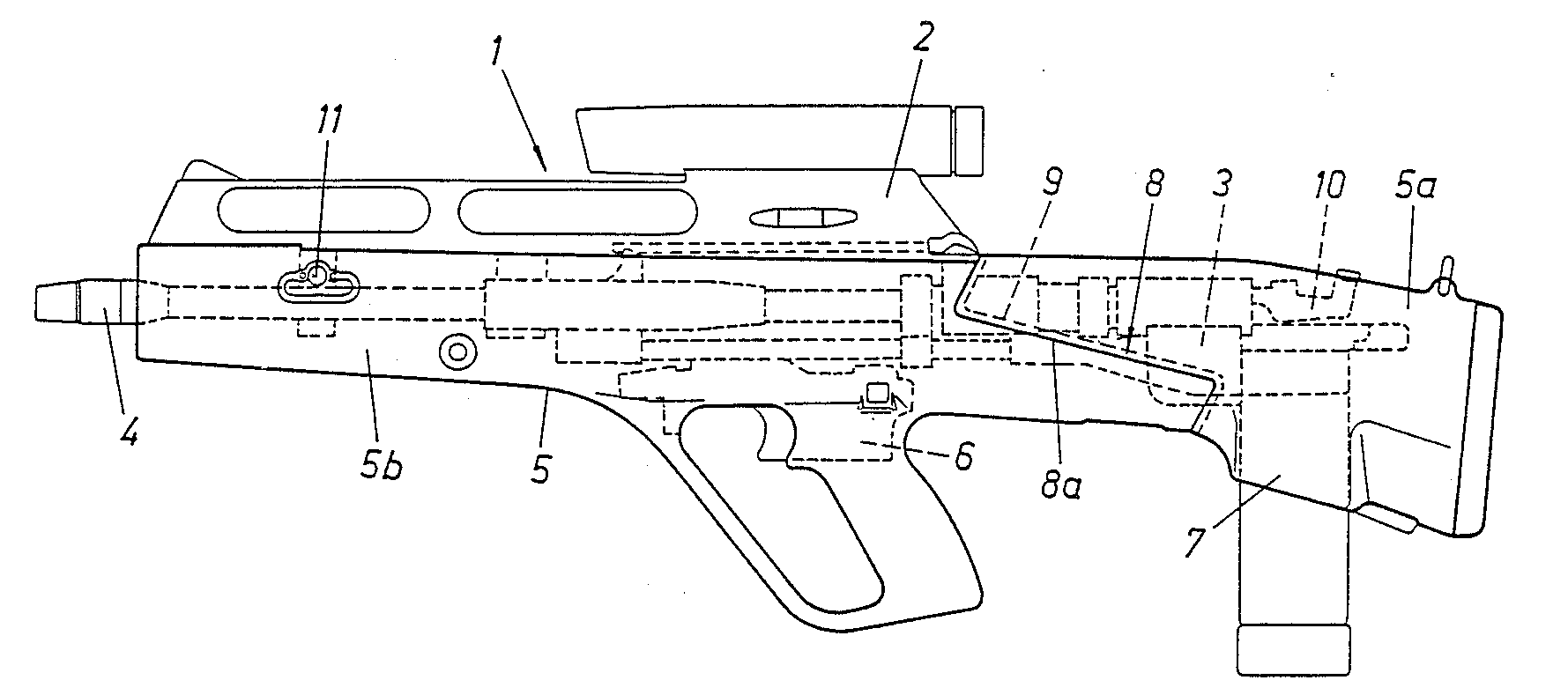
By the mid-1980s Steyr-Mannlicher were already leaders in unconventional small arms designs. In 1977 the Steyr AUG was adopted by the Austrian Army becoming the first generally adopted bullpup service rifle. As such Steyr-Mannlicher’s entry was inevitably a bullpup. Designed by Ulrich Zedrosser the rifle used a gas piston driven rising chamber mechanism which rose and fell to chamber rounds.
Left and right side views of the Steyr ACR, note the small AUG-style (Matthew Moss)
The rifle’s action is described in a 1988 patent (US #4949493) granted to Zedrosser, it explains that ” chamber member, which is separate from the barrel… is reciprocable between a firing position and a loading position in a direction which is transverse to the longitudinal direction of the barrel.” This means that the chamber rises and falls, with the rifle firing from an ‘open bolt’.
The patent goes on to explain the weapon’s action:
When the chamber member is in its loading position its chamber is freely accessible and at one end communicates through a loading opening of the firing block with the interior of a magazine holder and at the other end communicates through an ejection opening of the firing block with an ejection shaft. For the performance of the loading and unloading operation, a slider is provided, which is movable in the longitudinal direction of the barrel and carries a feeder, which is movable from a first end position… when the chamber member is in its loading position, and the movement of the chamber member from its loading position to its firing position is adapted to be initiated before the feeder reaches that end position in which the feeder extends into the loading opening.
One of the other patents (US #4817496) protecting the design explains the weapon’s gas system:
In order to provide a gas drive which is particularly simple and functionally reliable, light in weight and compact, the barrel is provided with a collar or the like, which constitutes a stationary pneumatic piston, and the pneumatic cylinder consists of a sliding sleeve, which surrounds the collar and is longitudinally displaceable between stops.
Patent diagram showing the Steyr ACR’s action (US Patent Office)
The Steyr ACR, like AAI’s entry, fires flechettes but Steyr’s are housed inside a cylindrical polymer case. The bullpup Steyr was the second shortest at 30 inches (76cm) and the lightest of the rifles submitted weighing 8.5 lbs (3.86kg).
The Steyr ACR borrows its ergonomics from its conventional forebearer, the AUG. With a moulded green plastic stock and a similar pistol grip, magazine release, trigger and safety layout. Unlike the AUG, however, the ACR uses an AR-15 style charging handle located at the rear of the sight mounting block and the stock extends further forward to encompass the barrel and gas system. The rifle could be fitted with a variable 1.5x to 3.5x optic or use iron sights.
Comparison of the Steyr ACR with the earlier AUG (Matthew Moss)
As discussed earlier the rifle does not use a conventional bolt, instead it uses a rising chamber, as a result the rifle fired from an open bolt. A live round only entered the chamber after the trigger had been pulled, thus reducing the potential for cook-offs. Spent polymer cases were pushed out of the chamber and ejected from an opening just in front of the magazine well.
Steyr’s Polymer Cased Flechette round (US Army)
Feeding from a 24-round box magazine, made from the same translucent material used in conventional AUG magazines. The magazine goes from double stack to single stack, to allow it to feed reliably, as a result the capacity had to be shortened. A high capacity drum magazine was planned but not provided for the trials. The polymer case held a fin stabilised 9.85 gr flechette with a moulded four piece sabot which broke up soon after exiting the muzzle. This was identified as a shortcoming as it risked hitting nearby troops.
ACR Program Summary recognised the Steyr ACR entry as “the simplest weapon, the simplest round, and the most cost effective approach of any of the ACR contenders.” The report noted that the weapon’s “greatest current deficiency is its poor round to round dispersion characteristics.” This was a criticism levelled at both the flechette firing entries, it essentially ended the US Army’s interest in flechette firing individual weapons, relegating the concept to larger area effect weapon systems.
If you enjoyed the video and this article please consider supporting our work here.
On the 21st May 1943, Birmingham Small Arms Ltd.’s chief designer Henry Faulkner, along with Roger Wackrow, patented a series of features used on the BESAL light machine gun. The BESAL had begun life as a stop-gap, emergency light machine gun design which could be quickly manufactured alongside the Bren gun in the event of an imminent German invasion of Britain.
Instead, the design evolved into BSA’s attempt to have the BESAL adopted as a subsitute standard light machine gun. The images below comes from three British patents filed in May 1943 and granted in October 1945. They show the basic layout of the BESAL along with detailed drawings of the sight, universal magazine adaptor, bolt and the take down knob.
You can find our in-depth video, complete with disassembly, here.


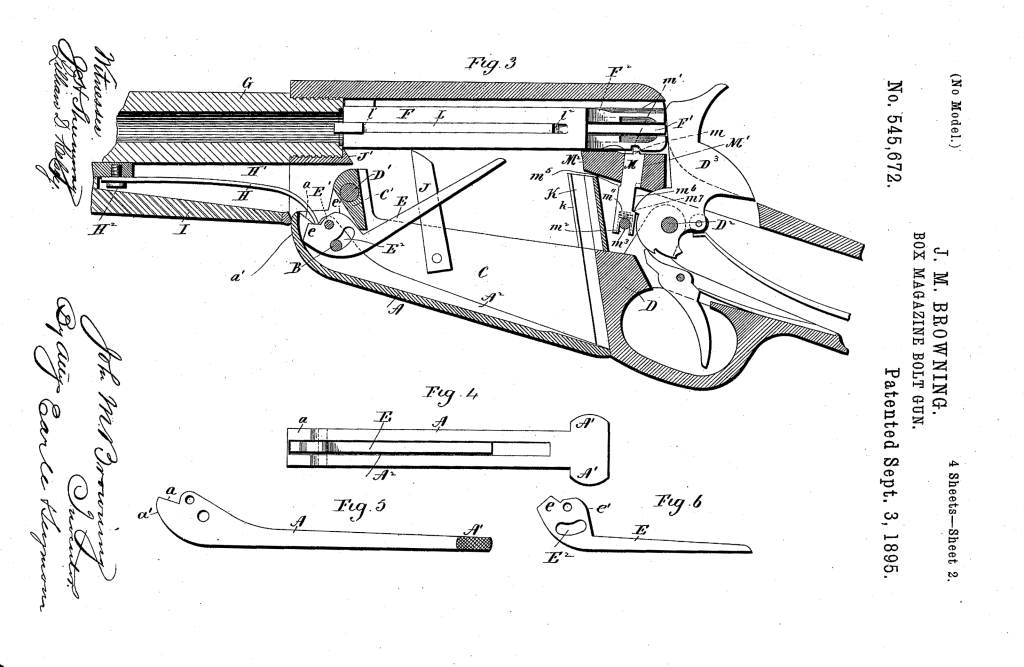

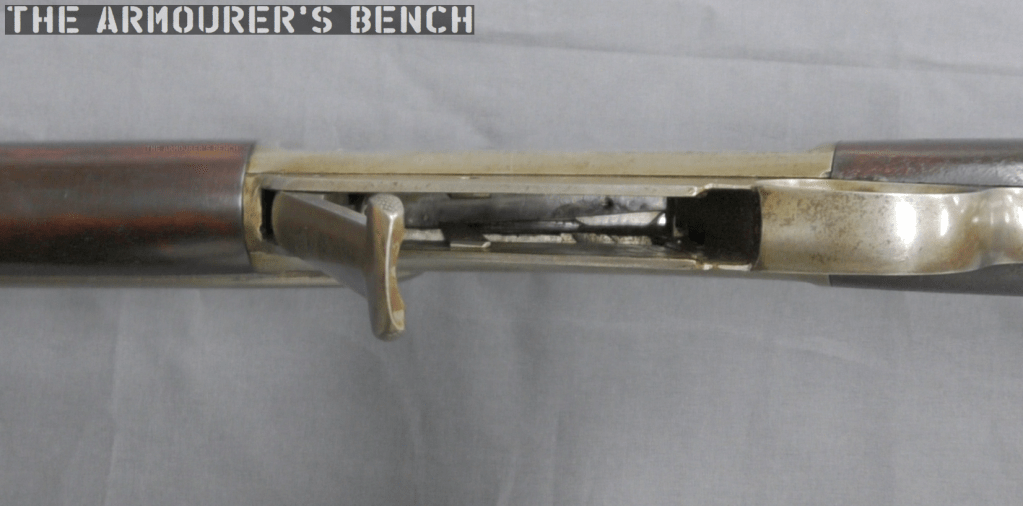
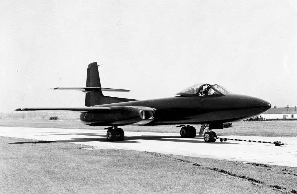
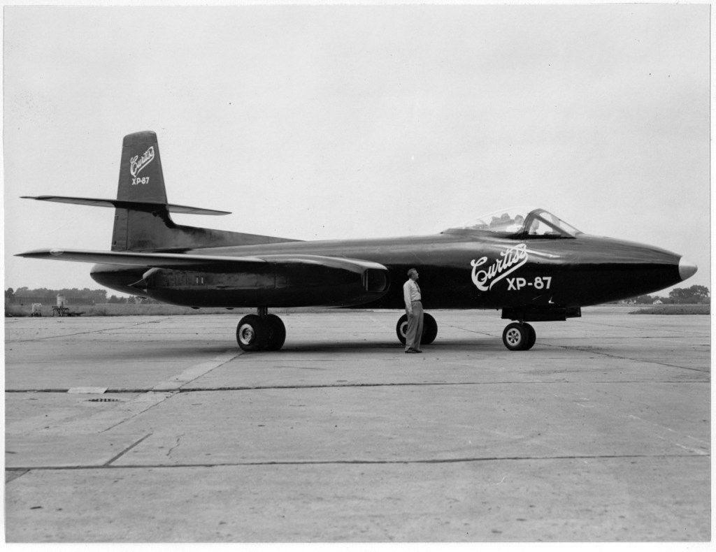
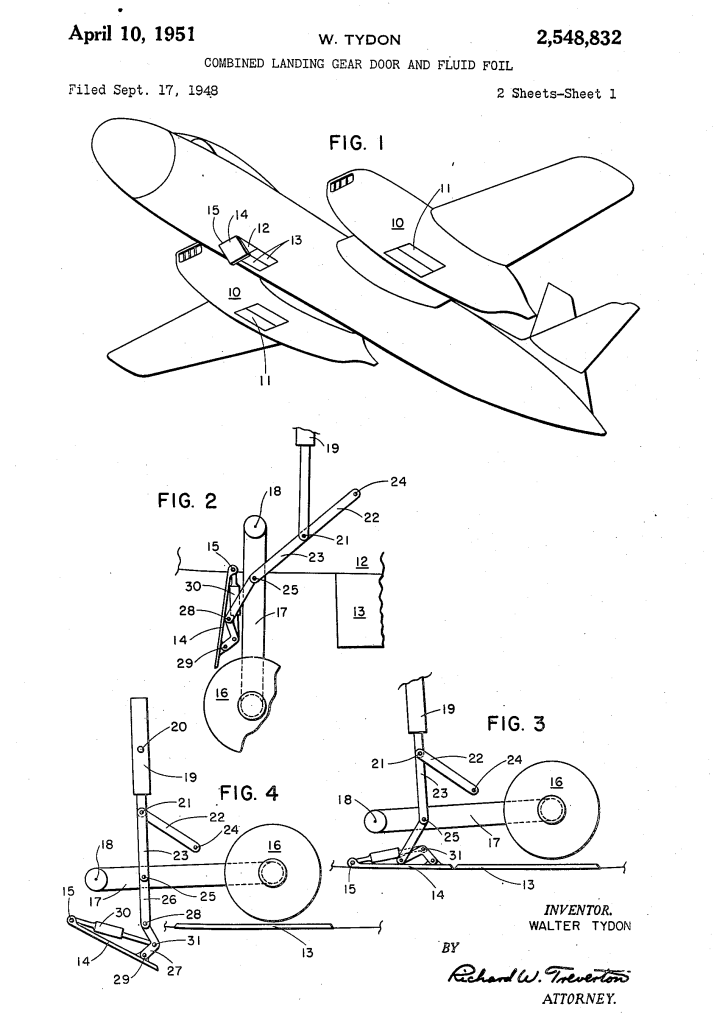
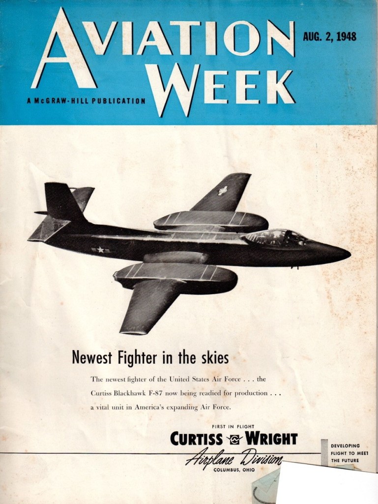

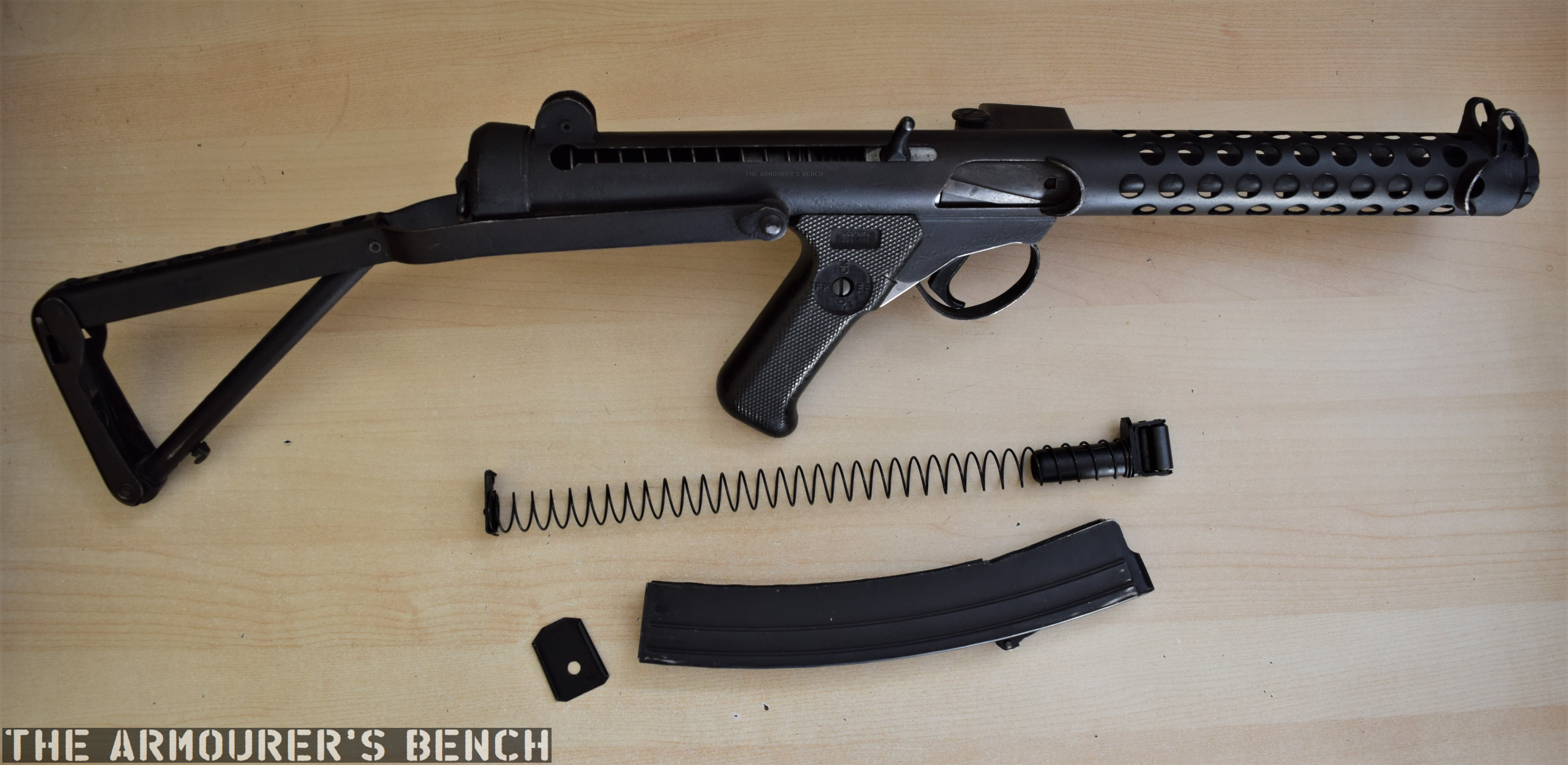

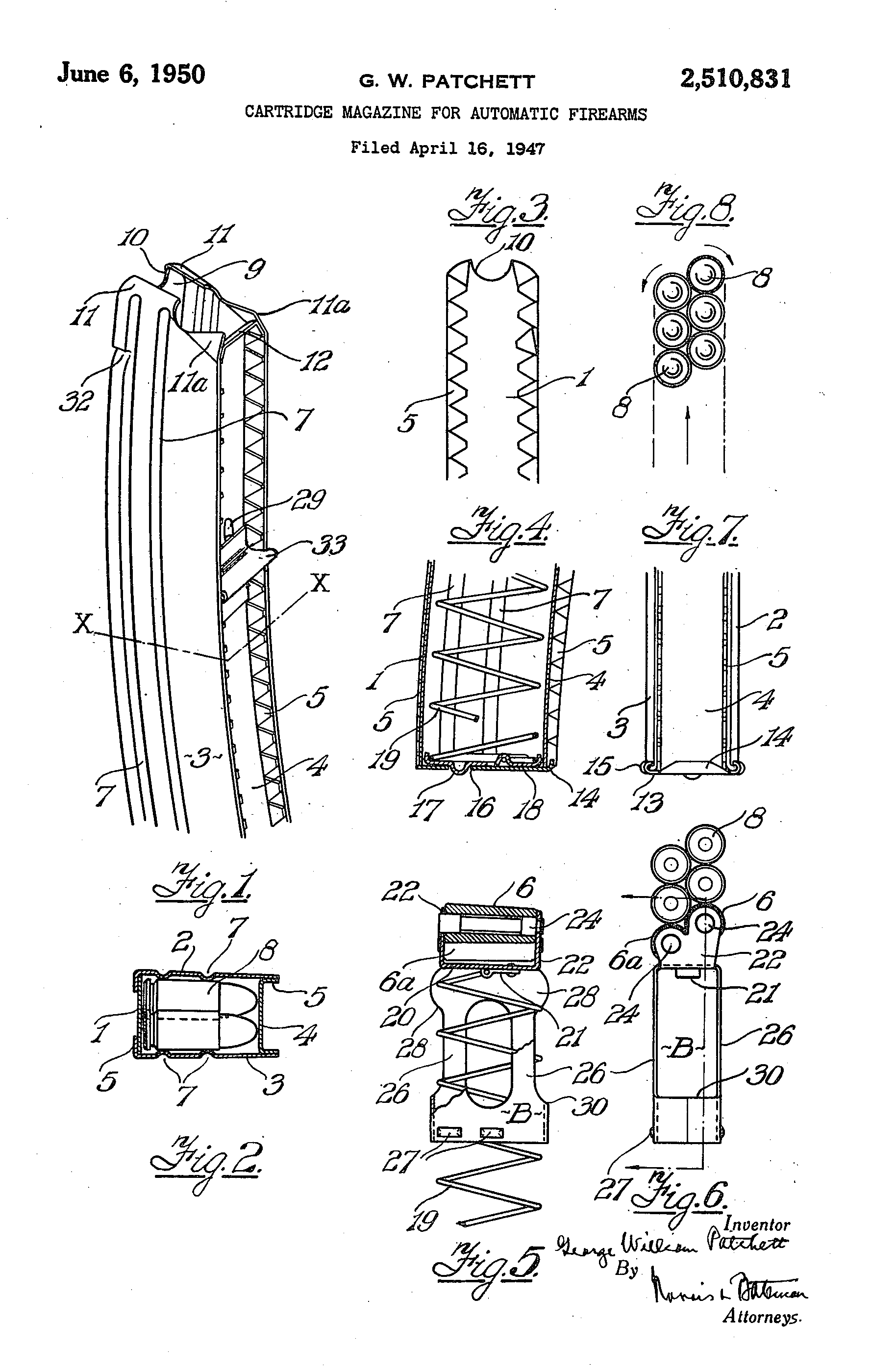
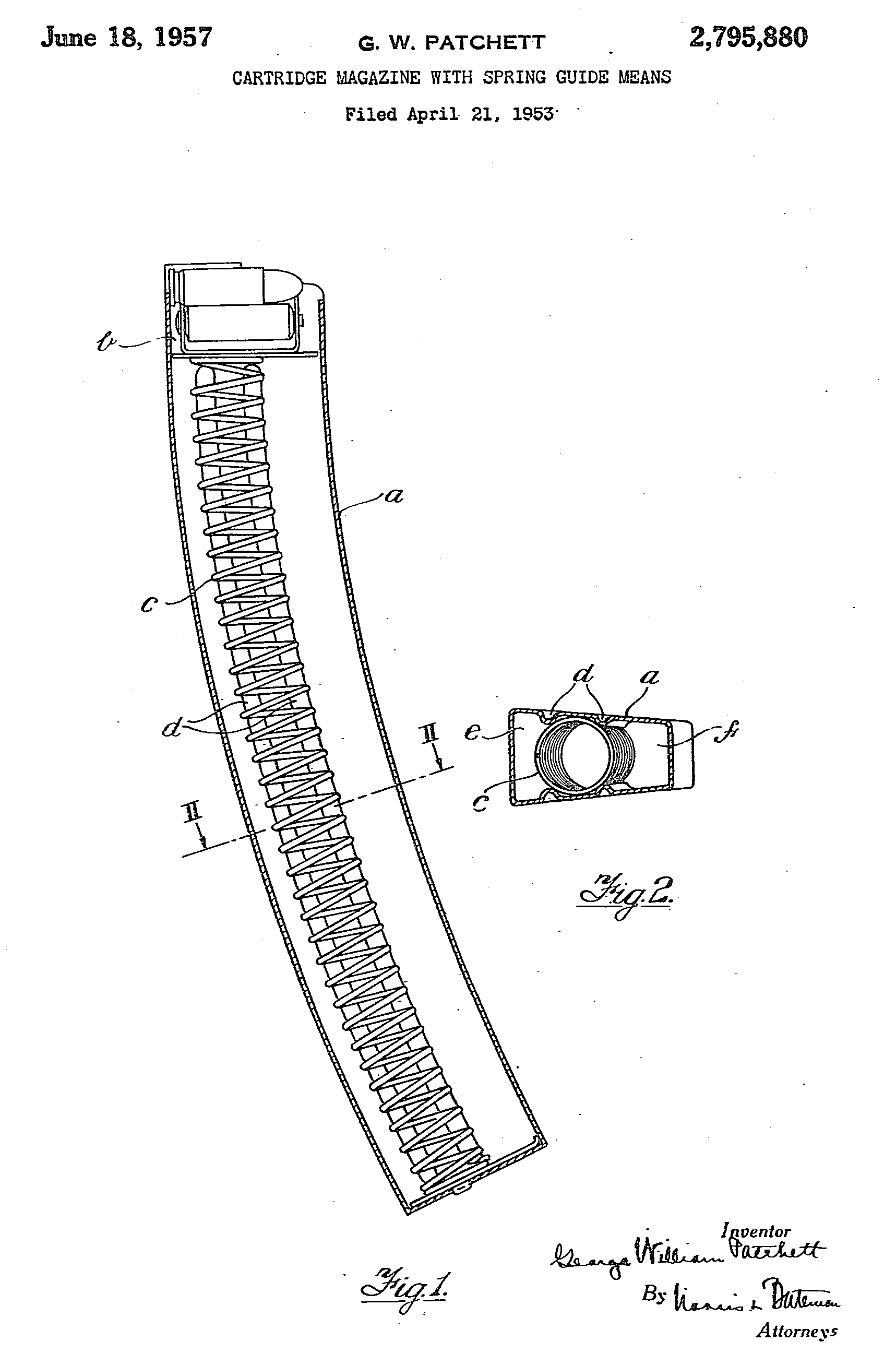
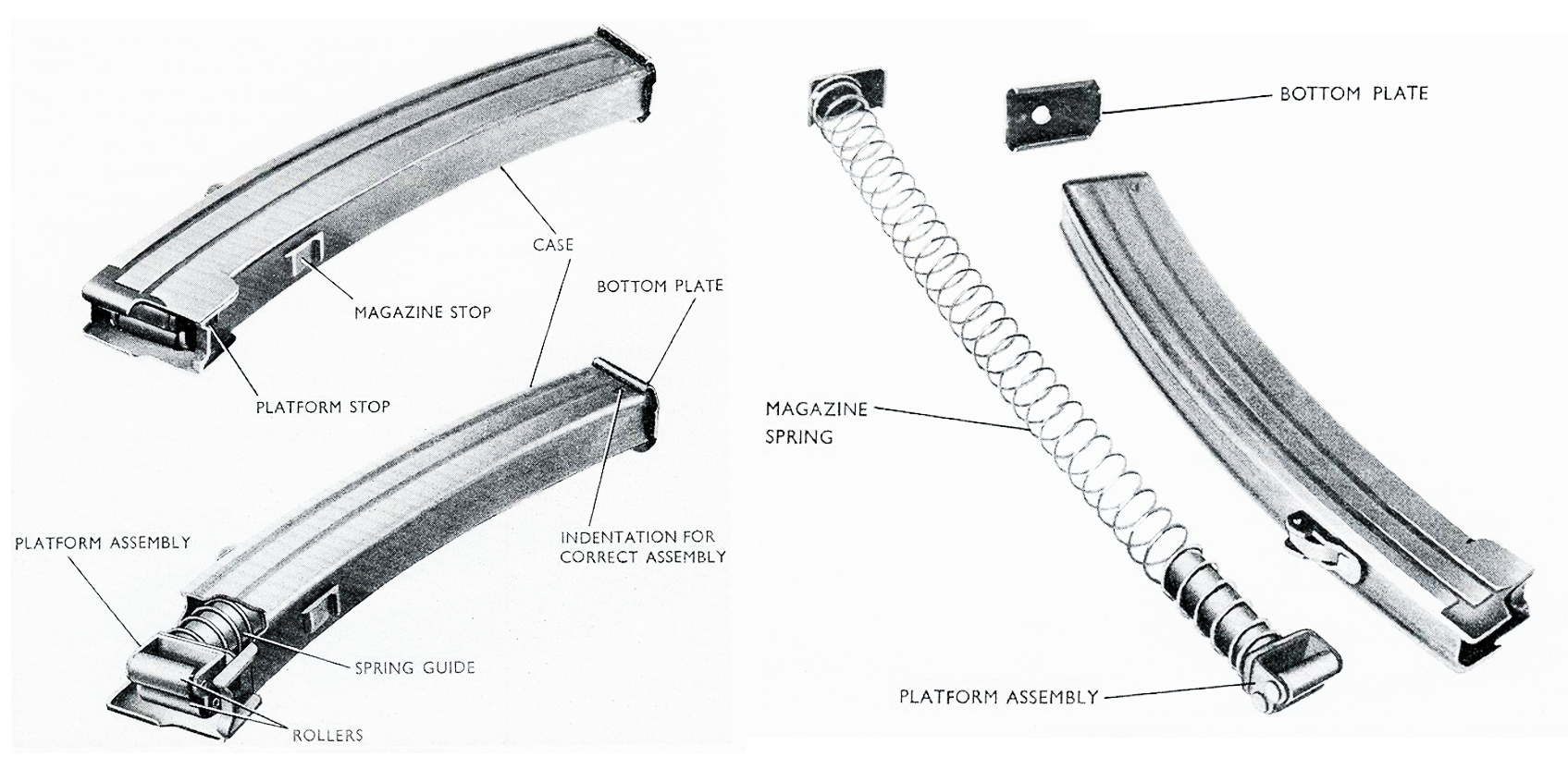
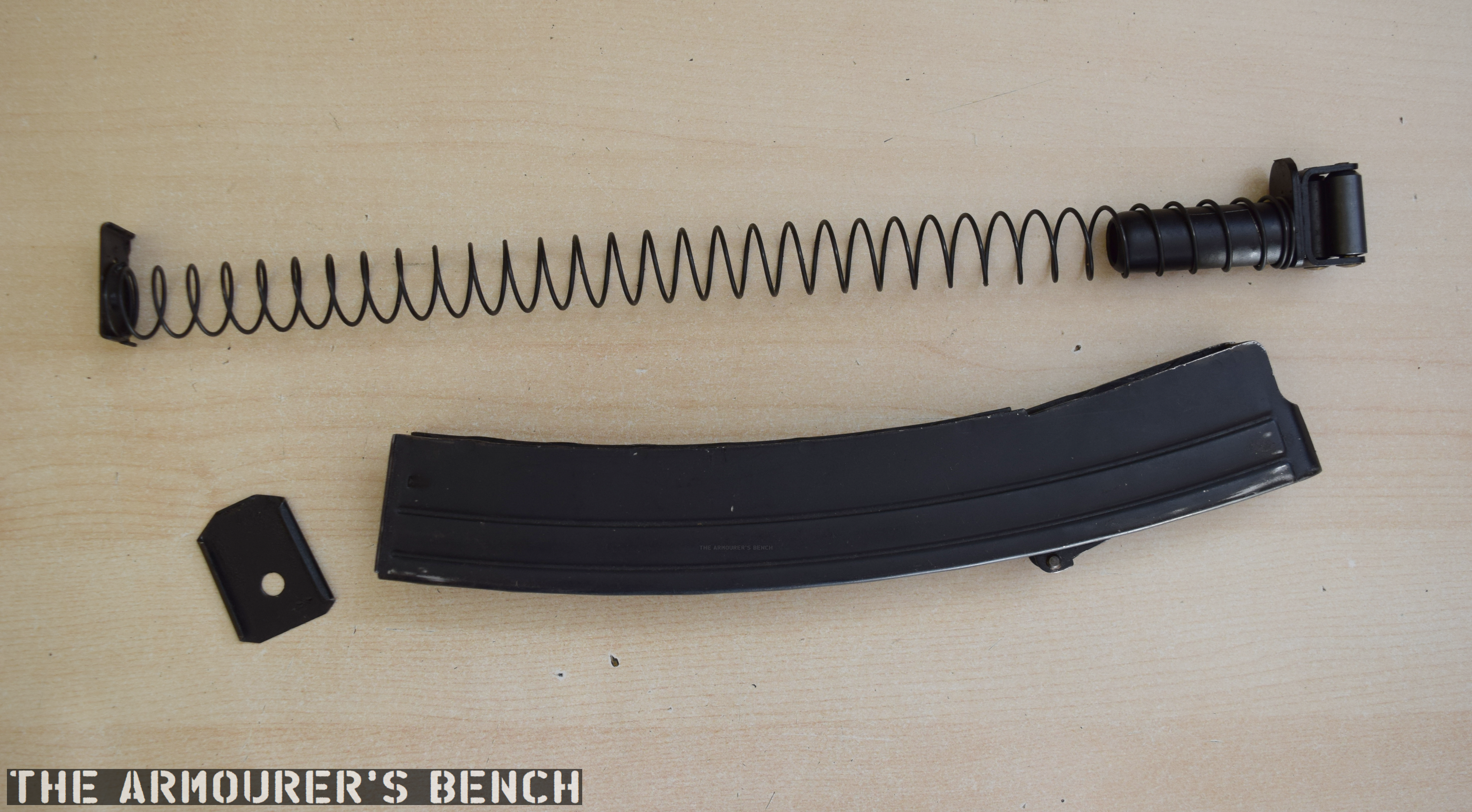
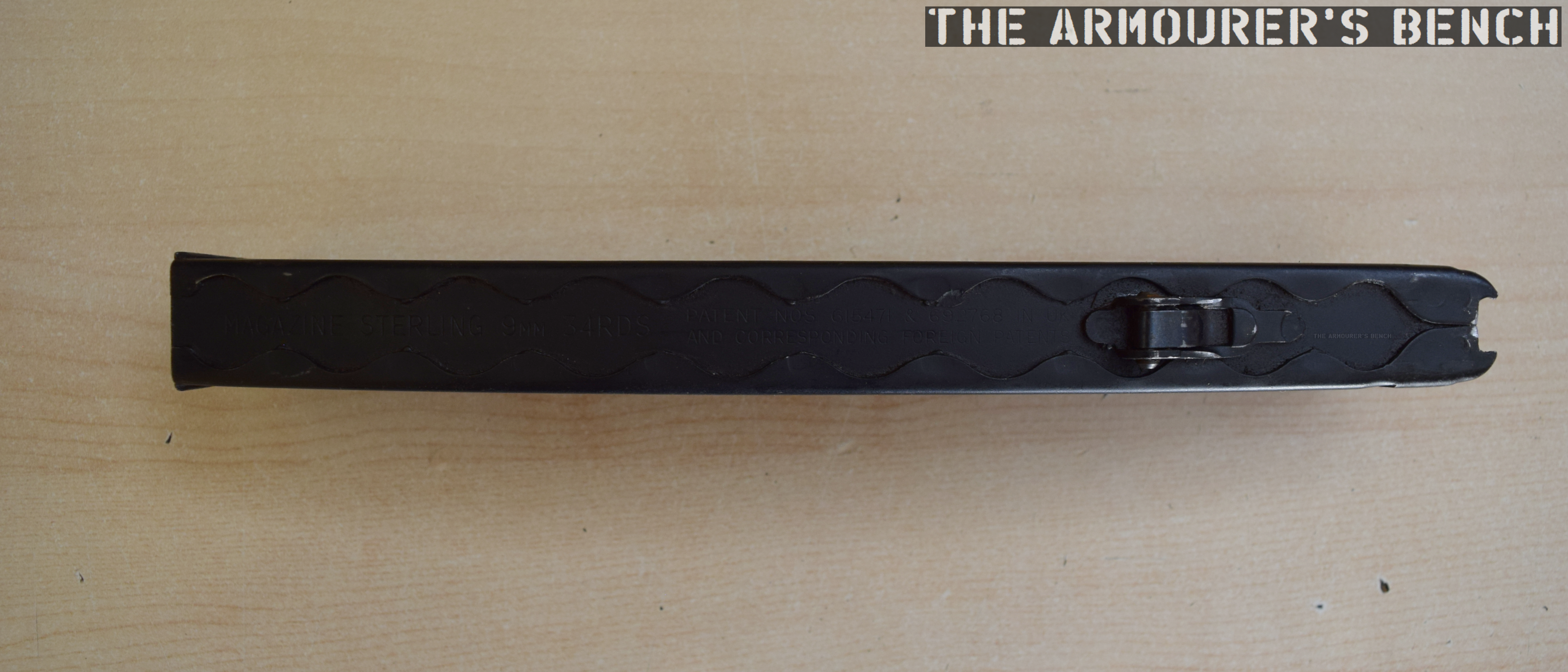
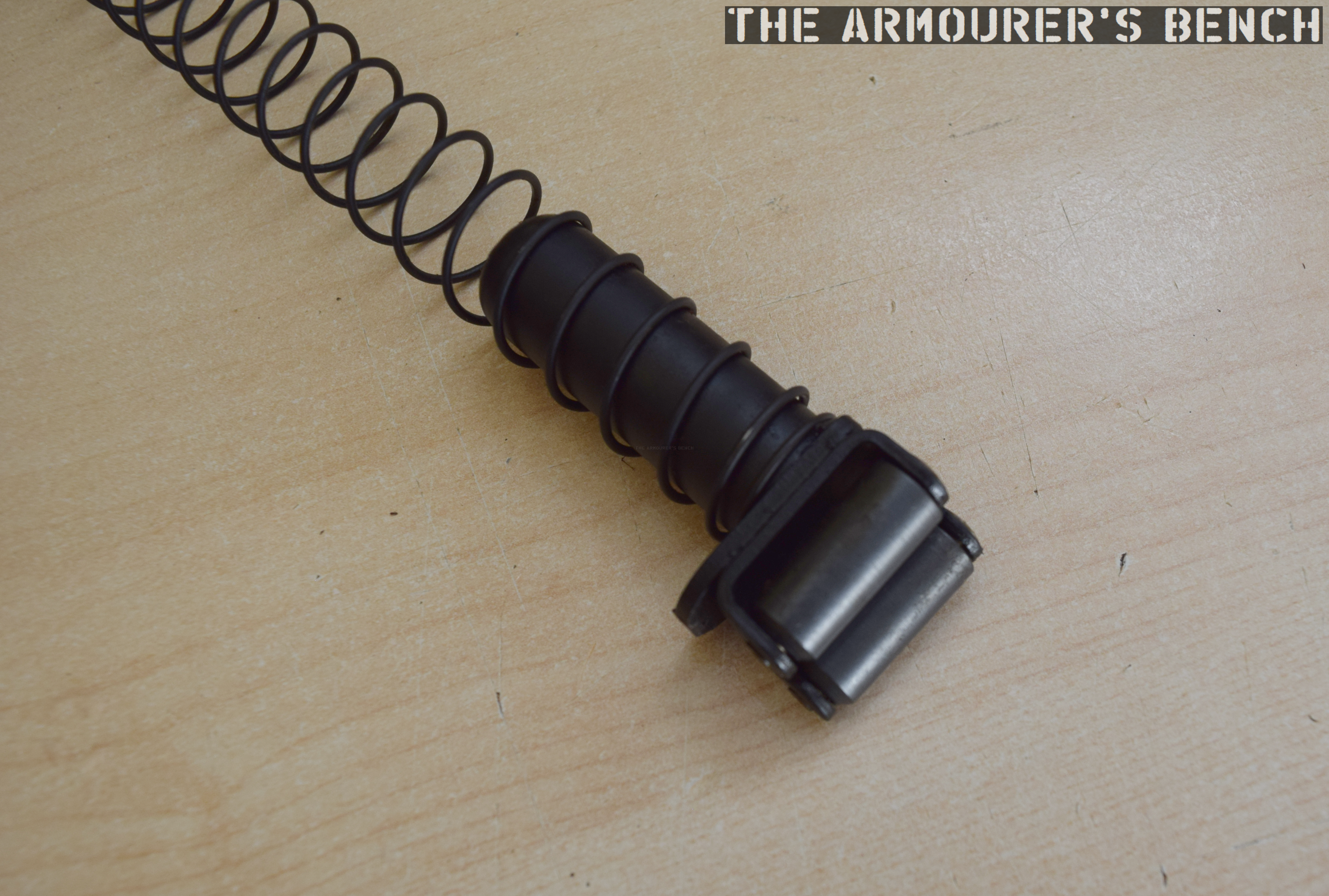
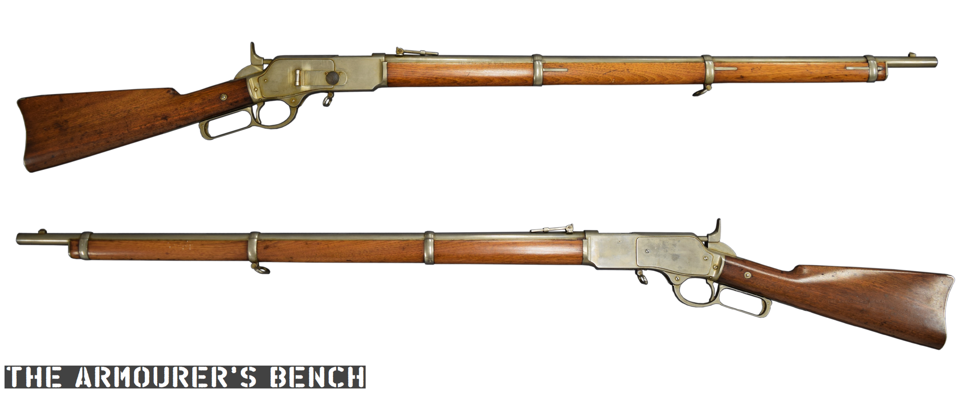

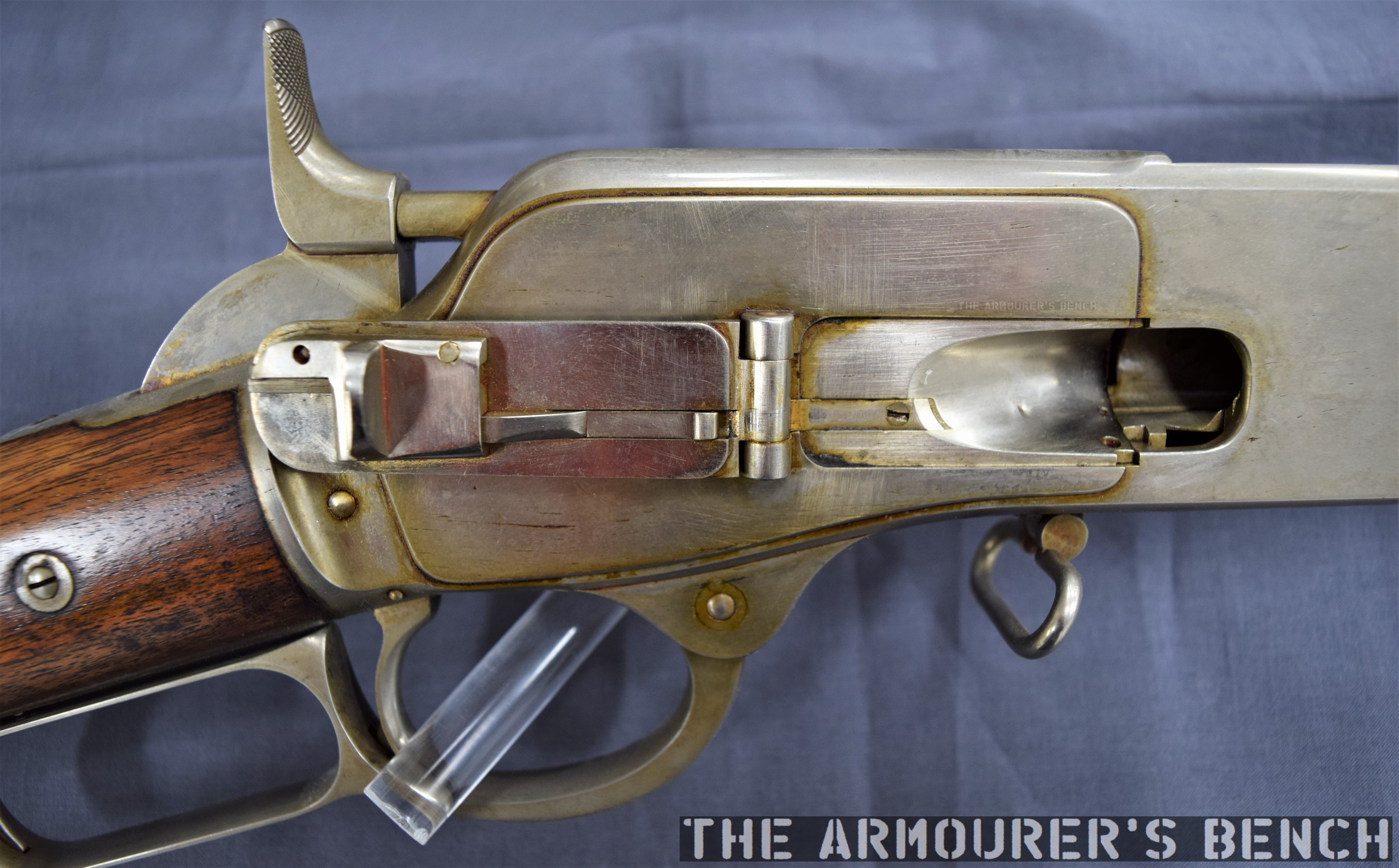


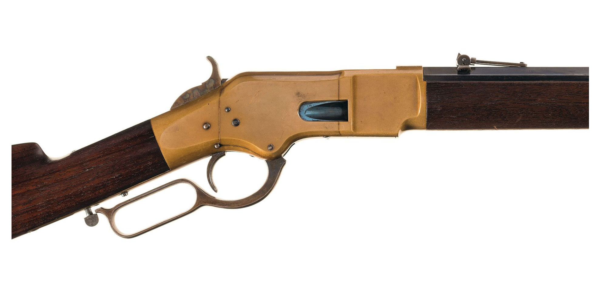
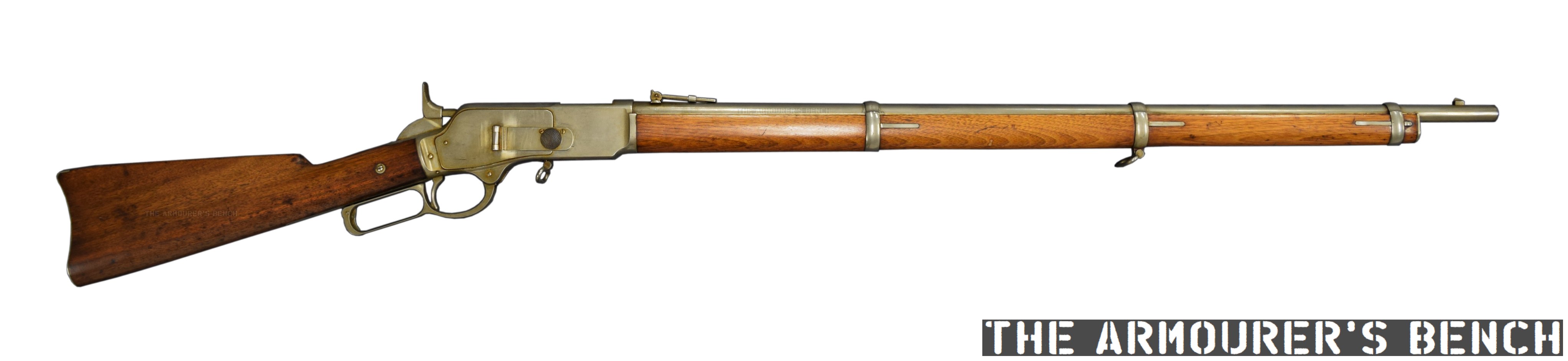
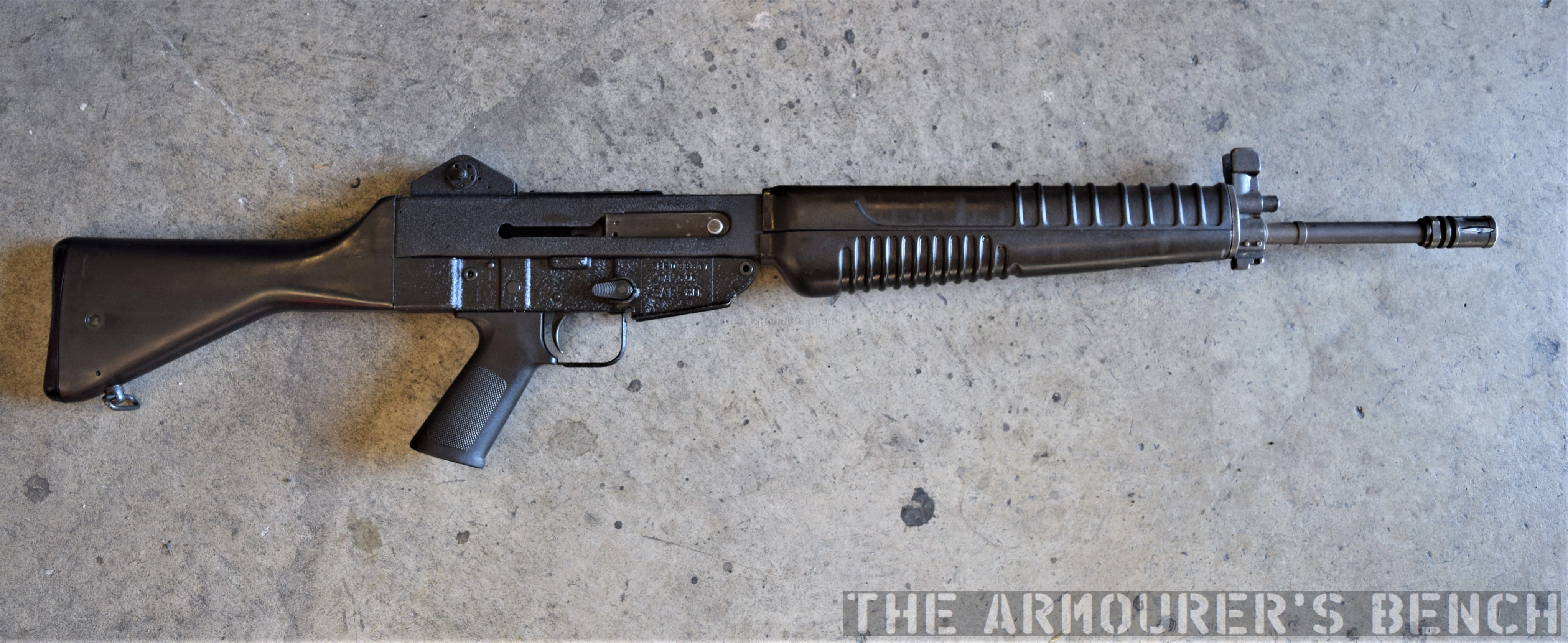
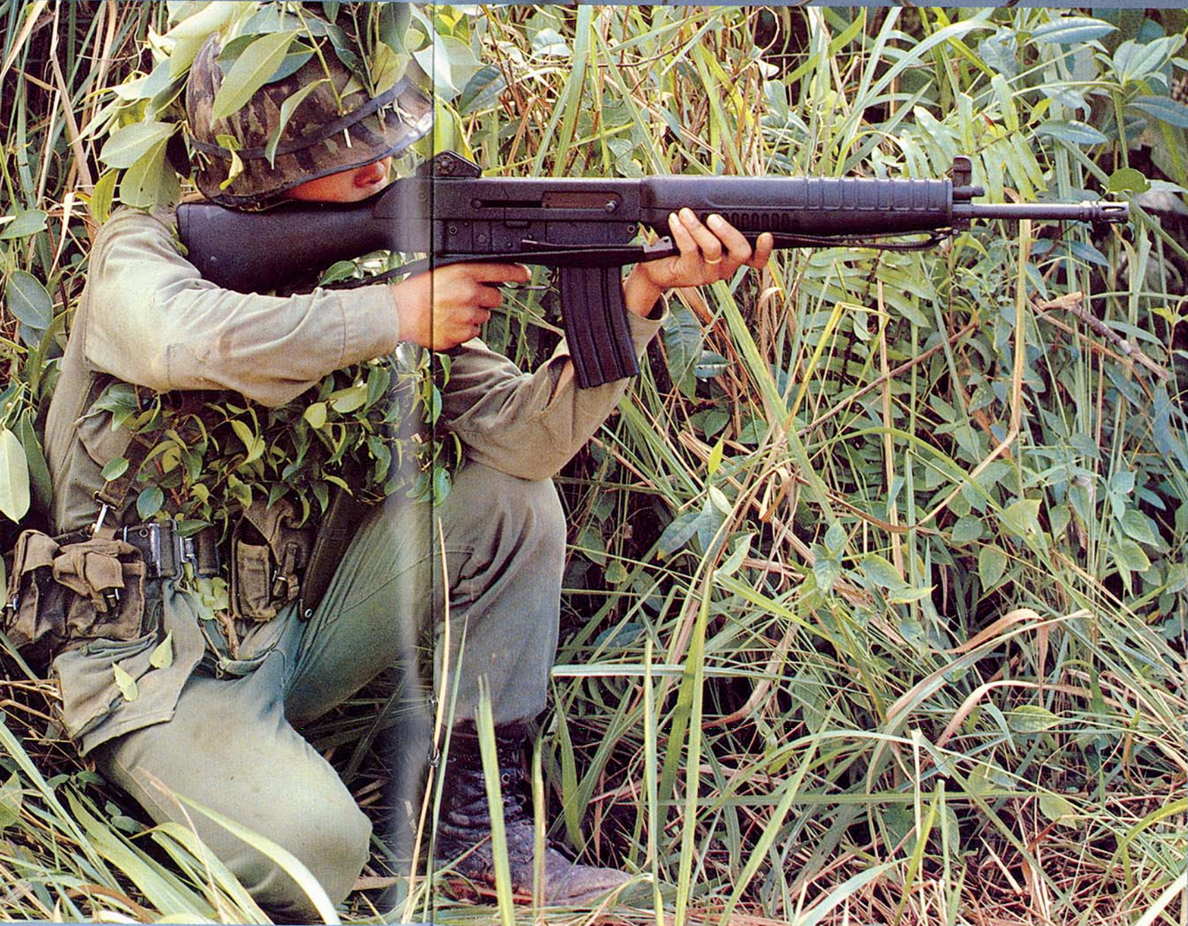
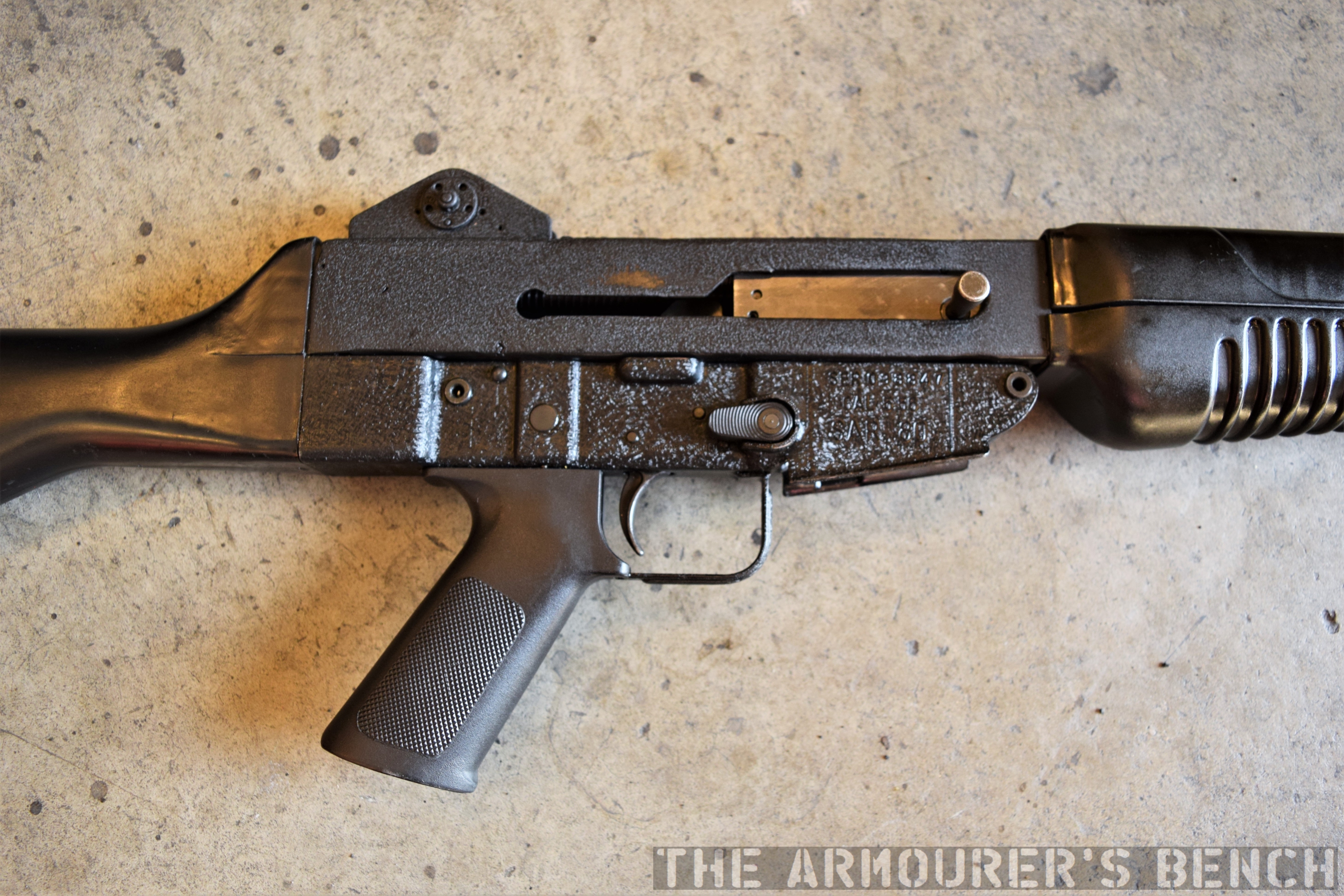
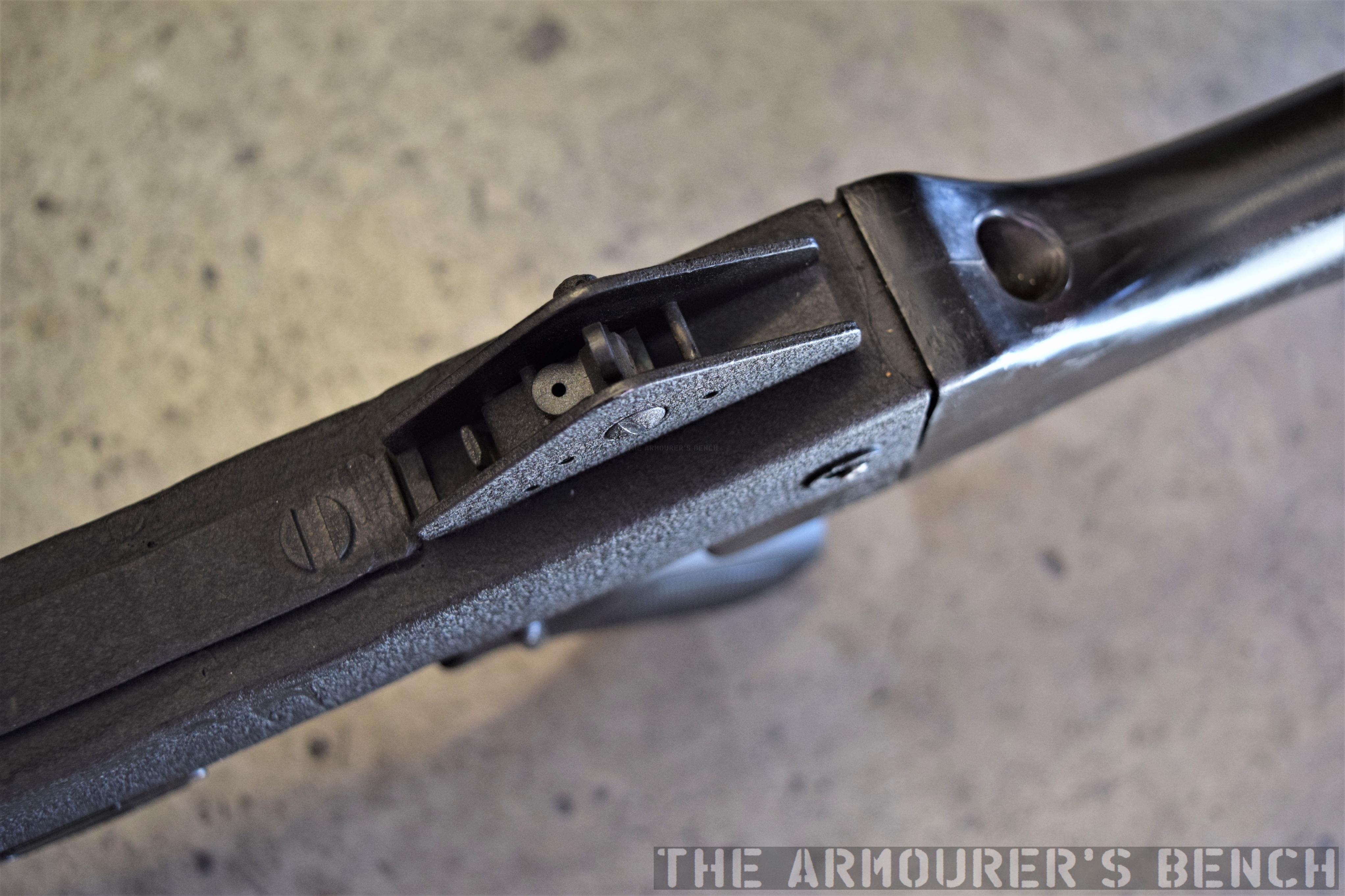
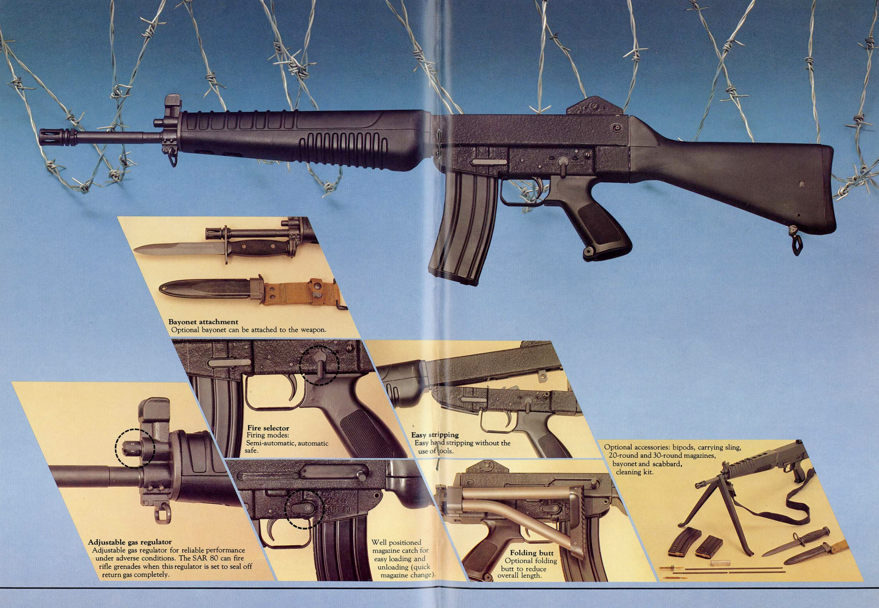
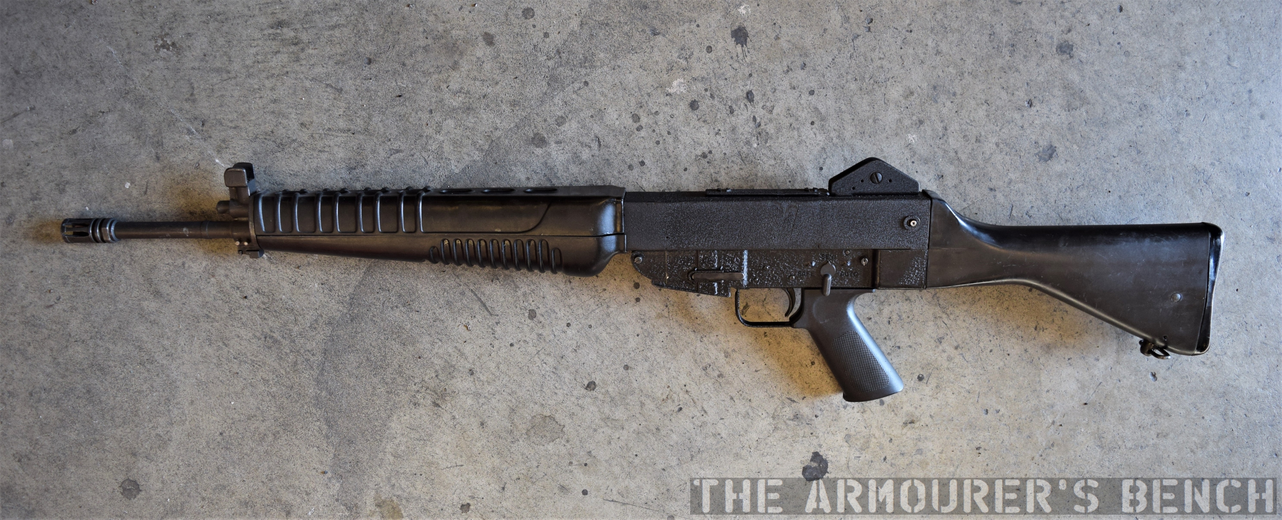


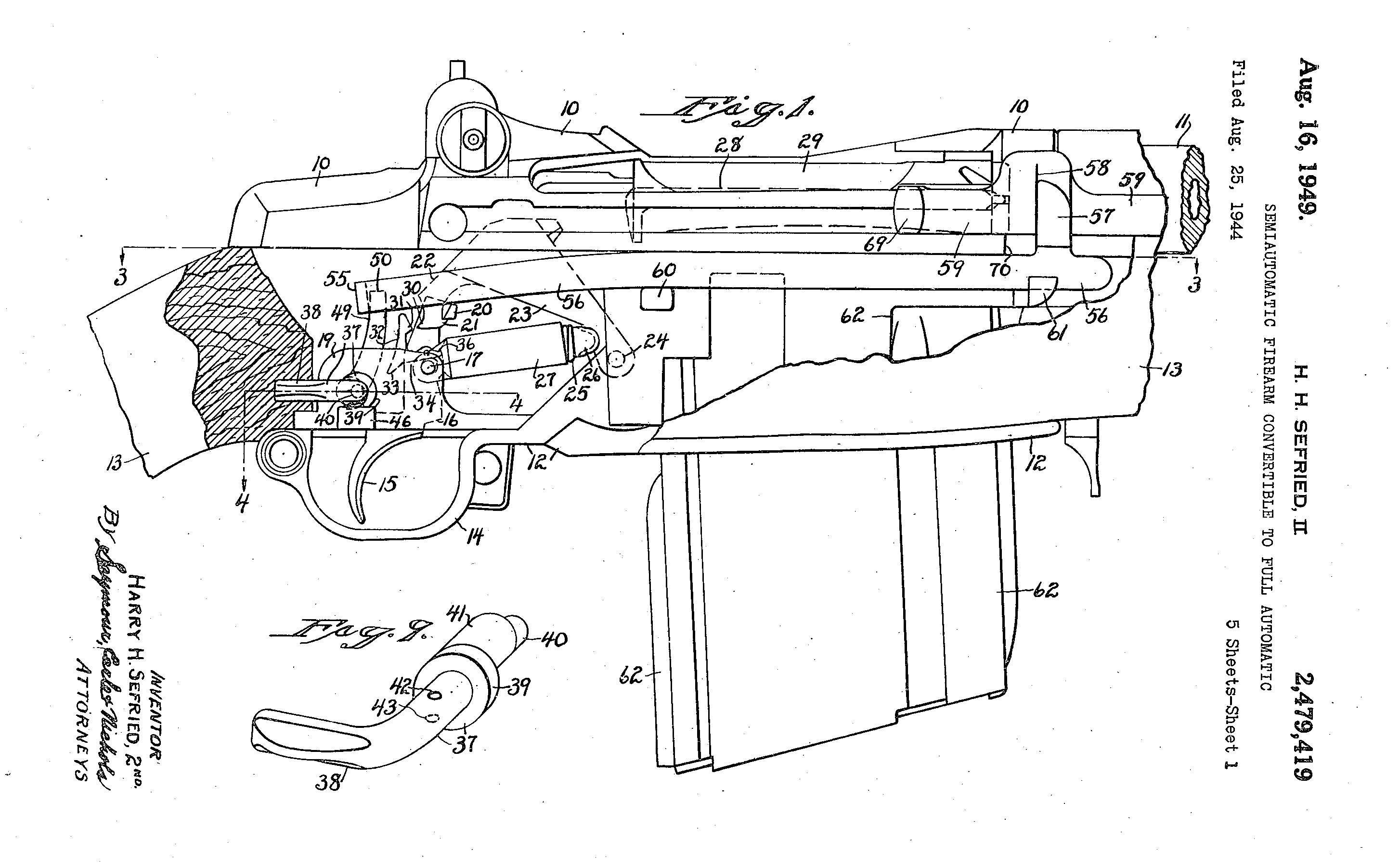
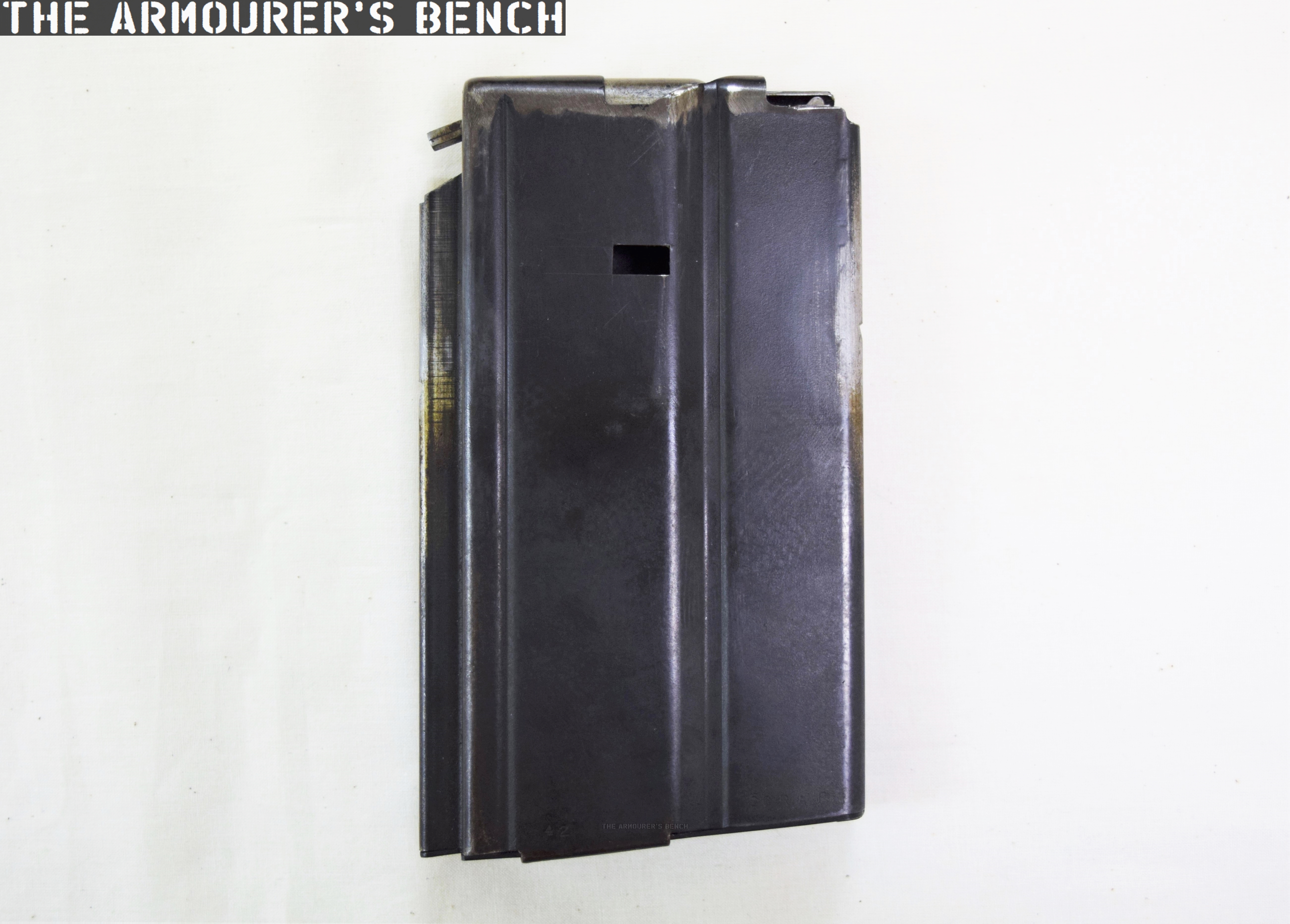
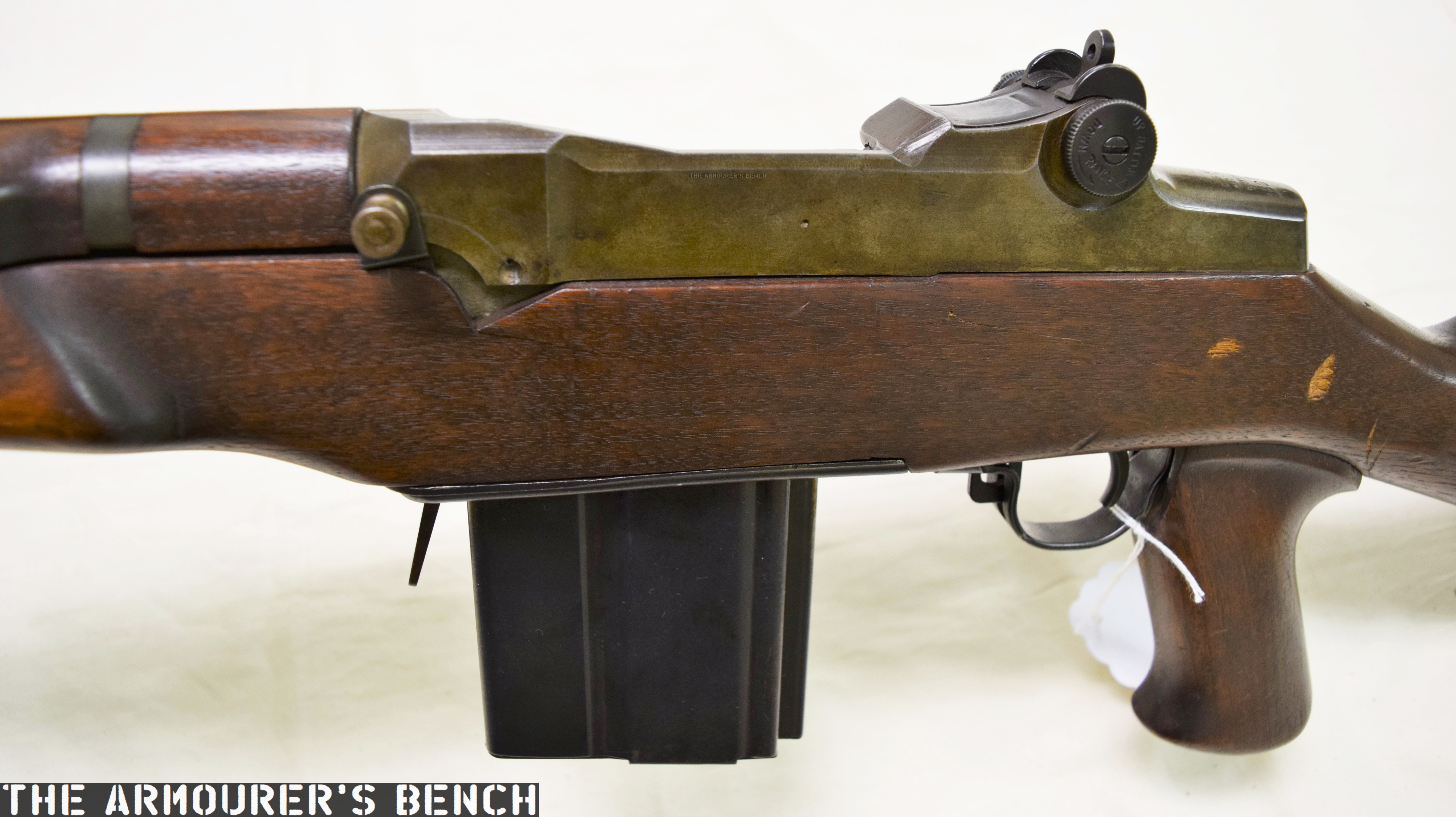
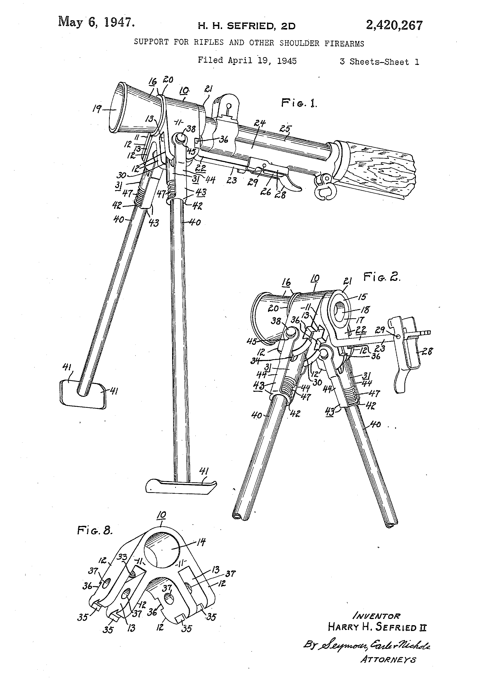
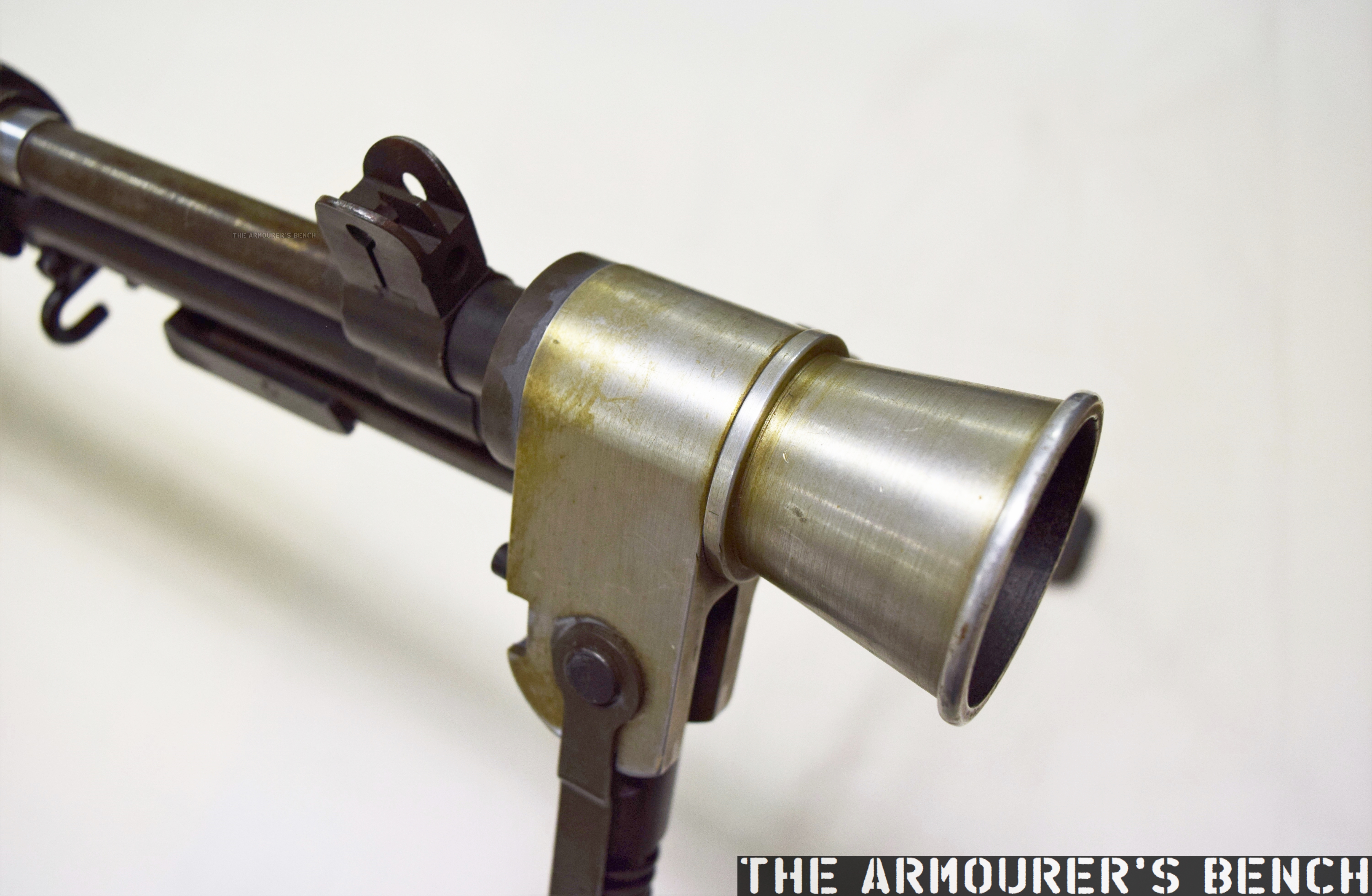

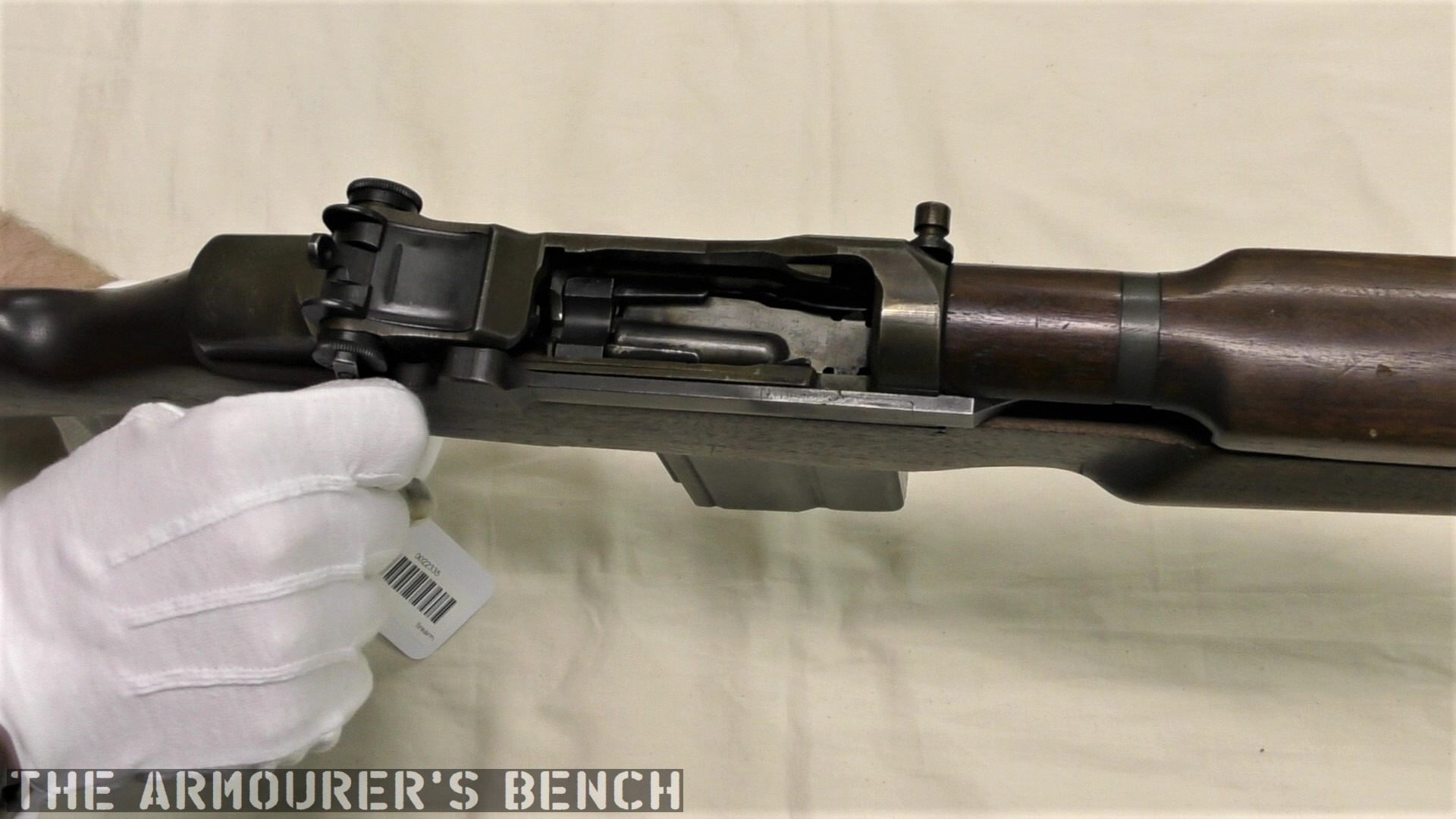

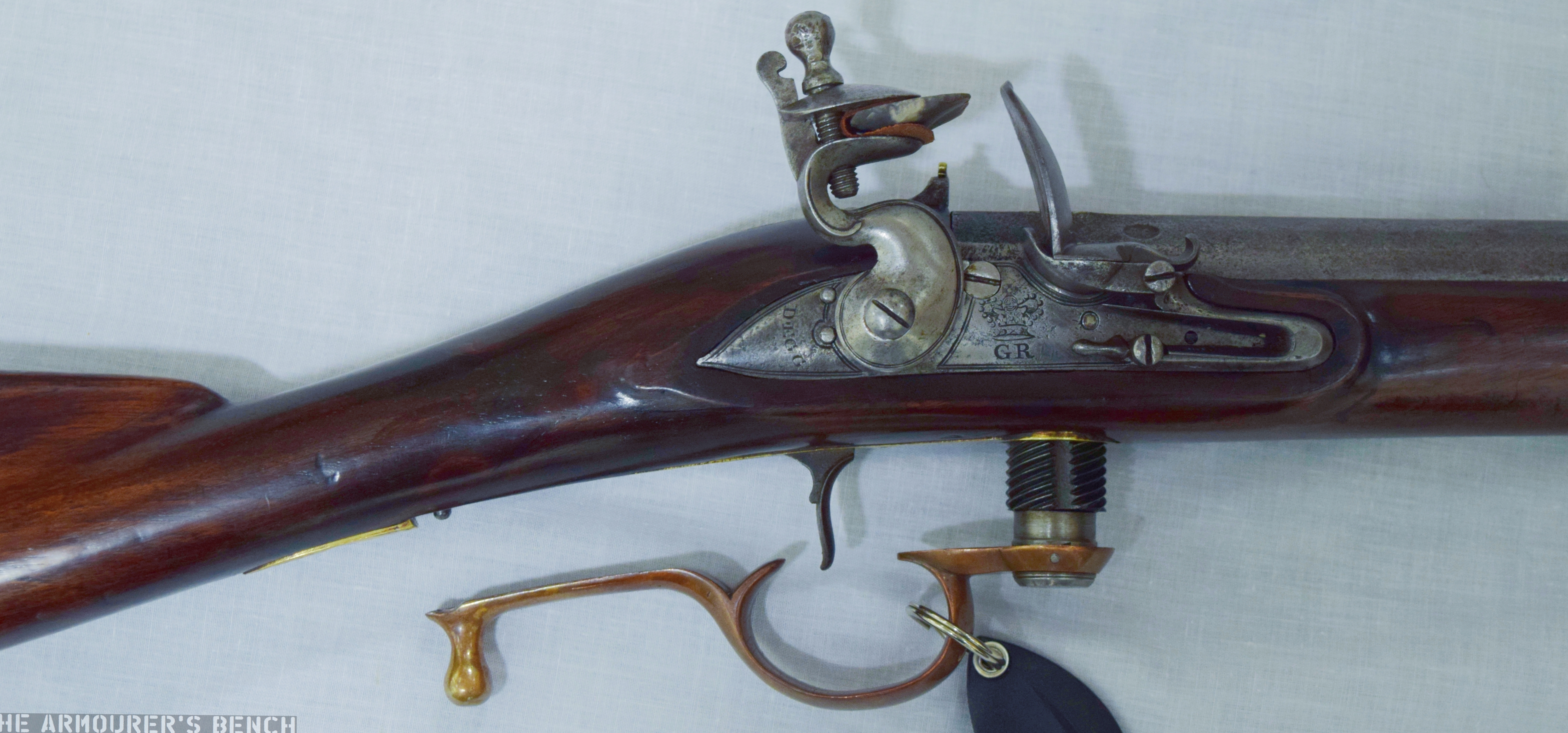
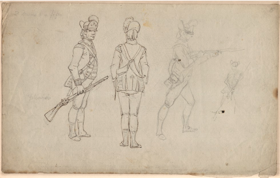
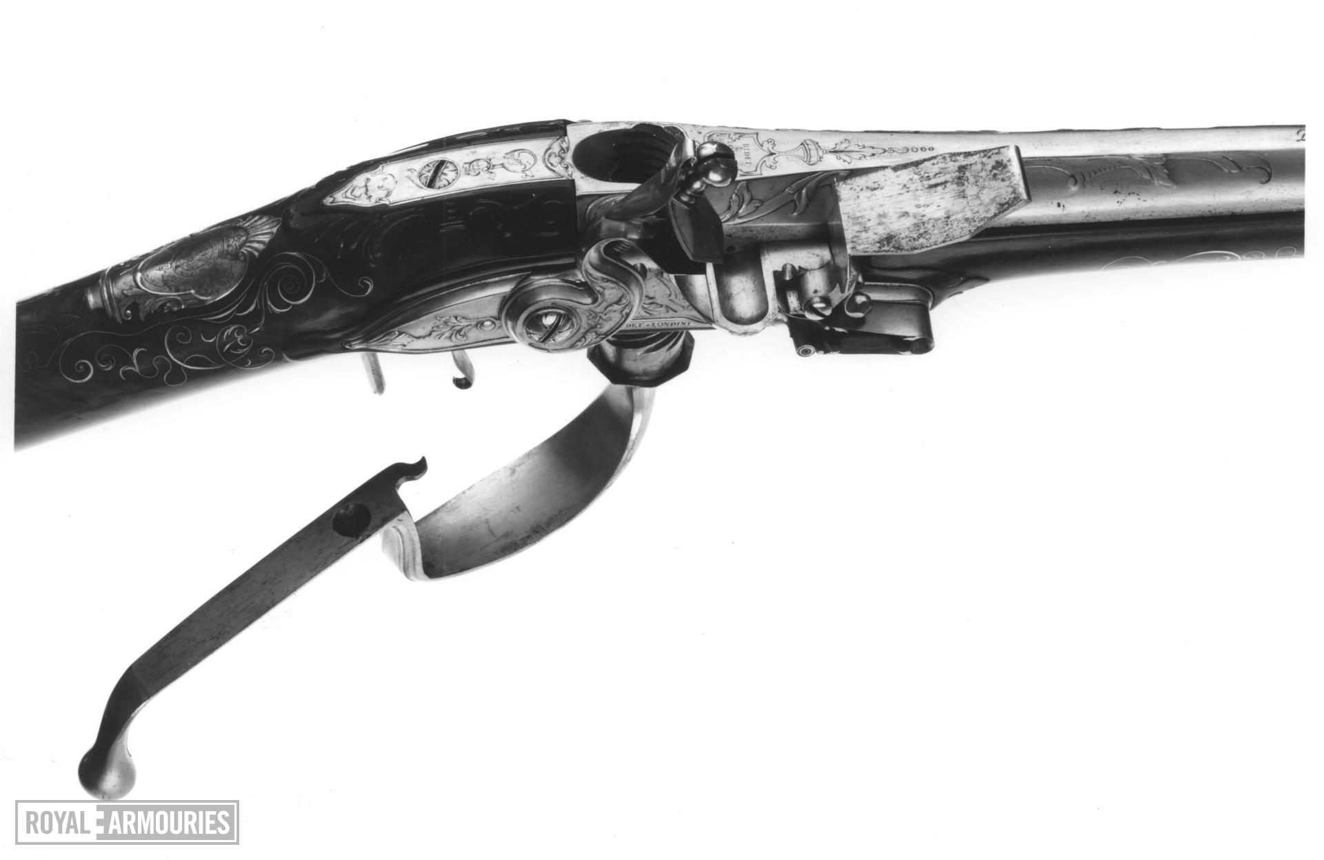
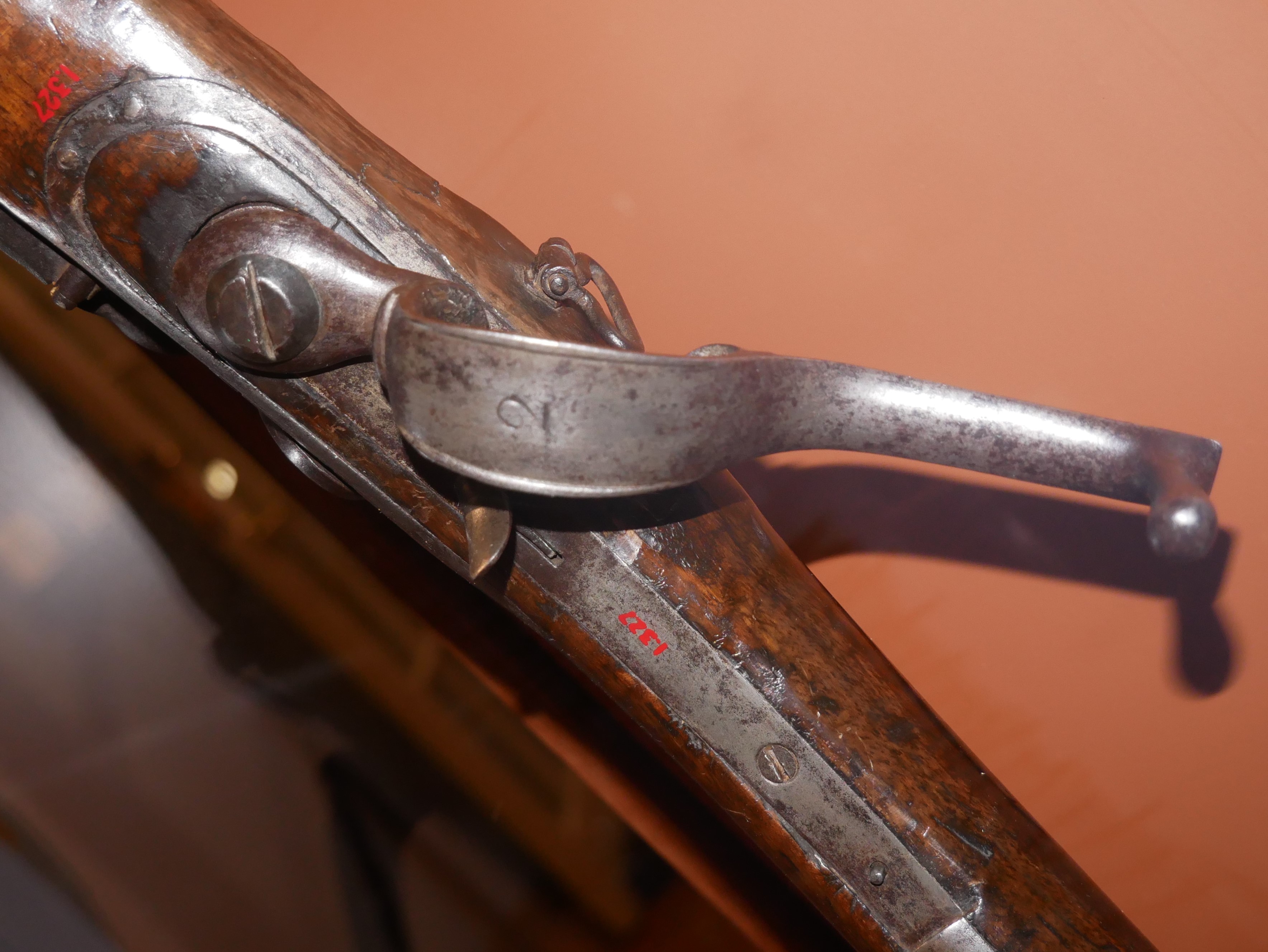
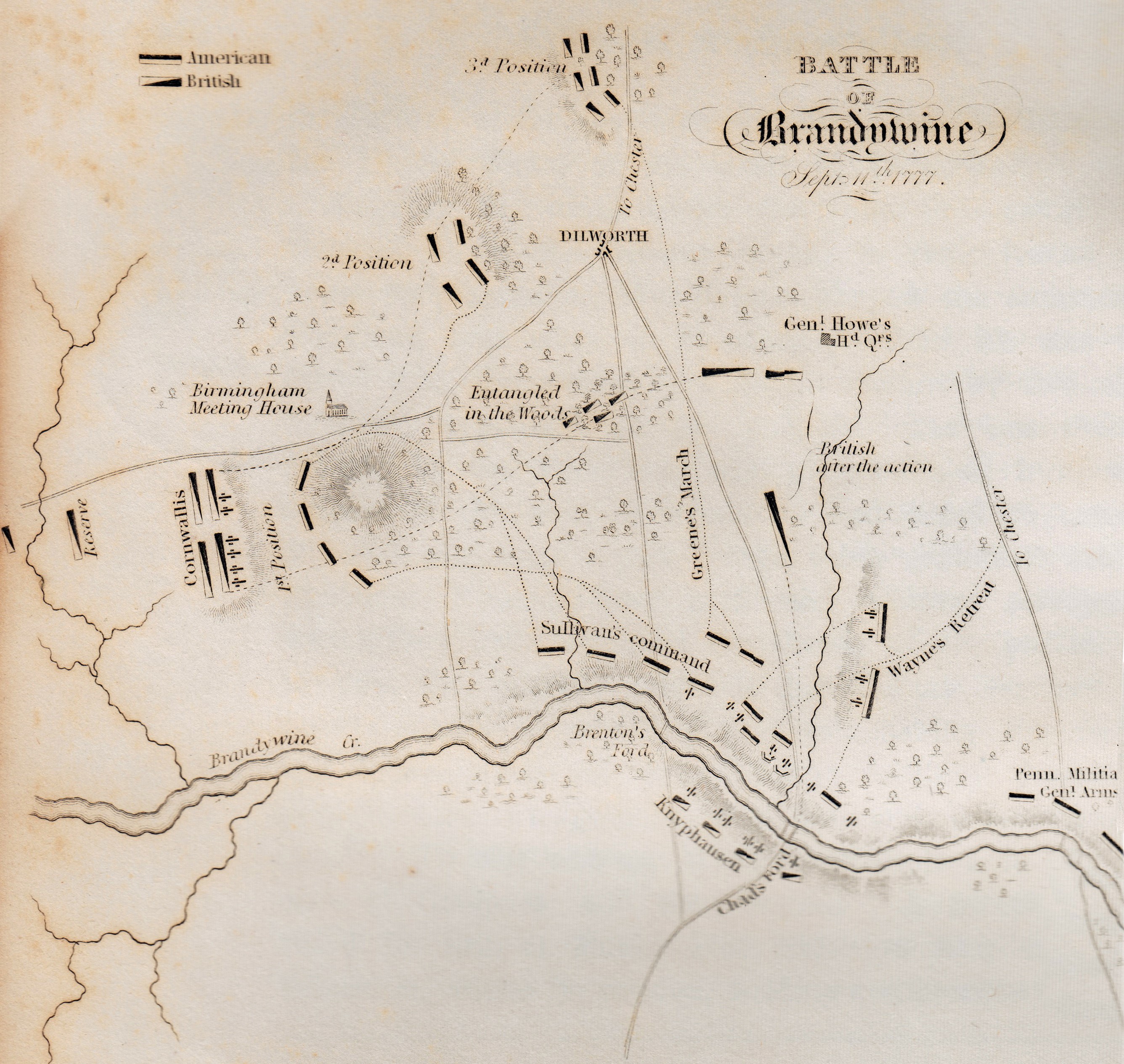
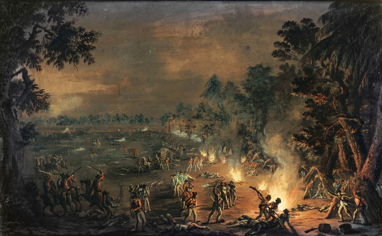
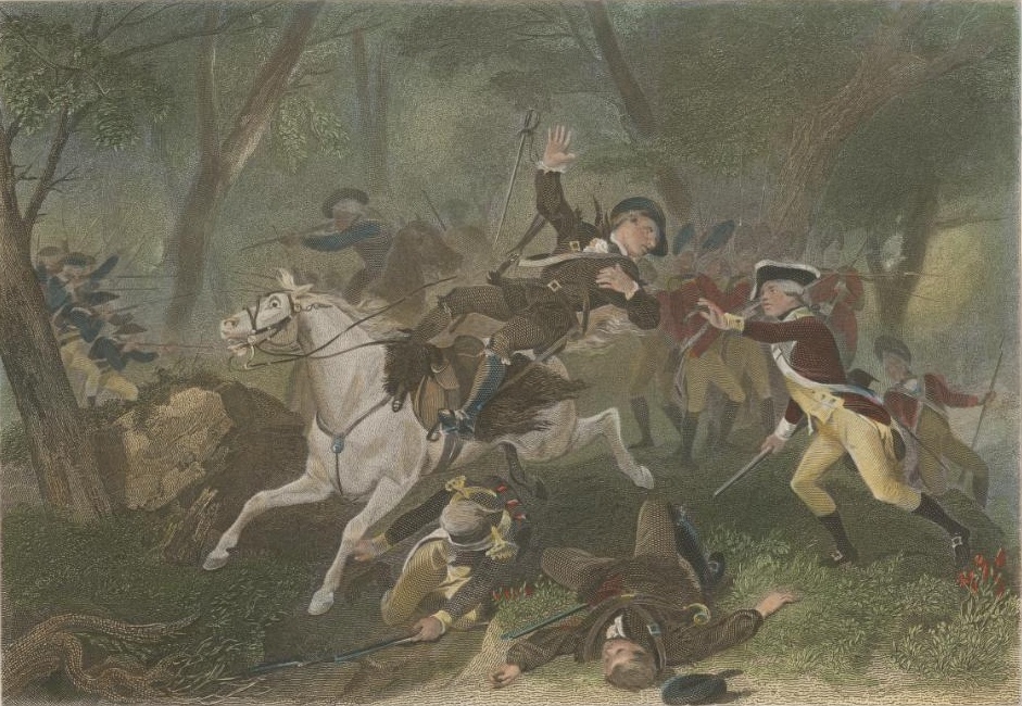
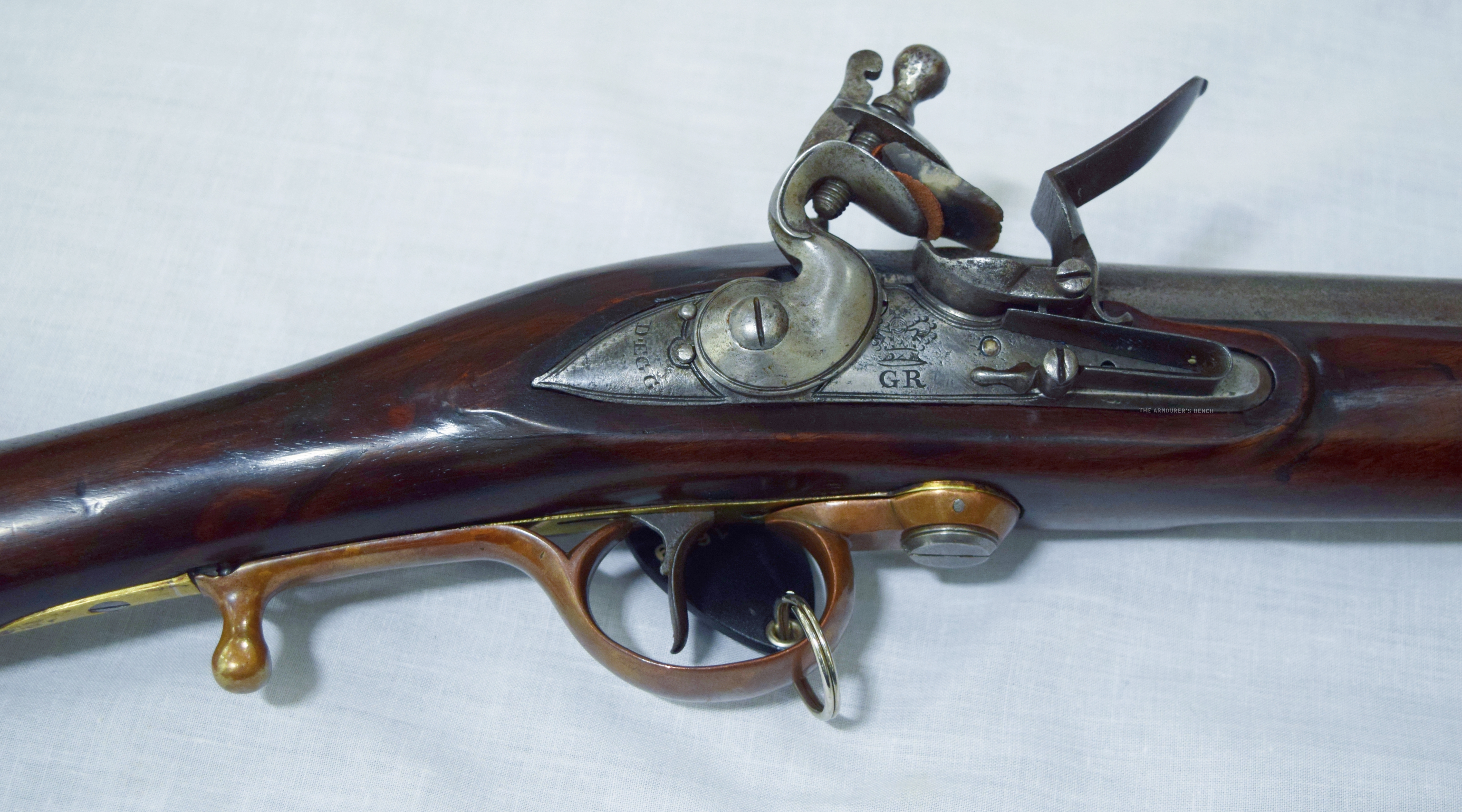
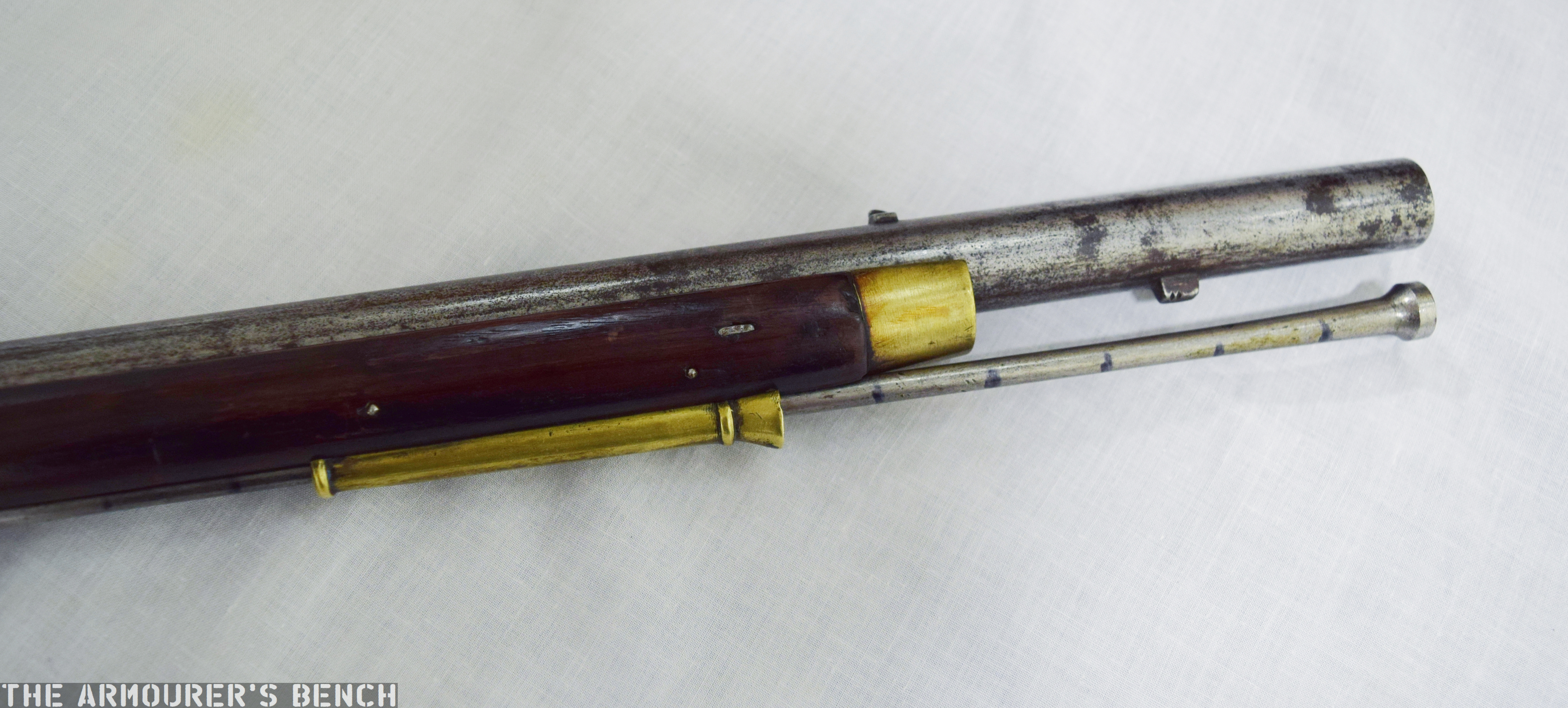
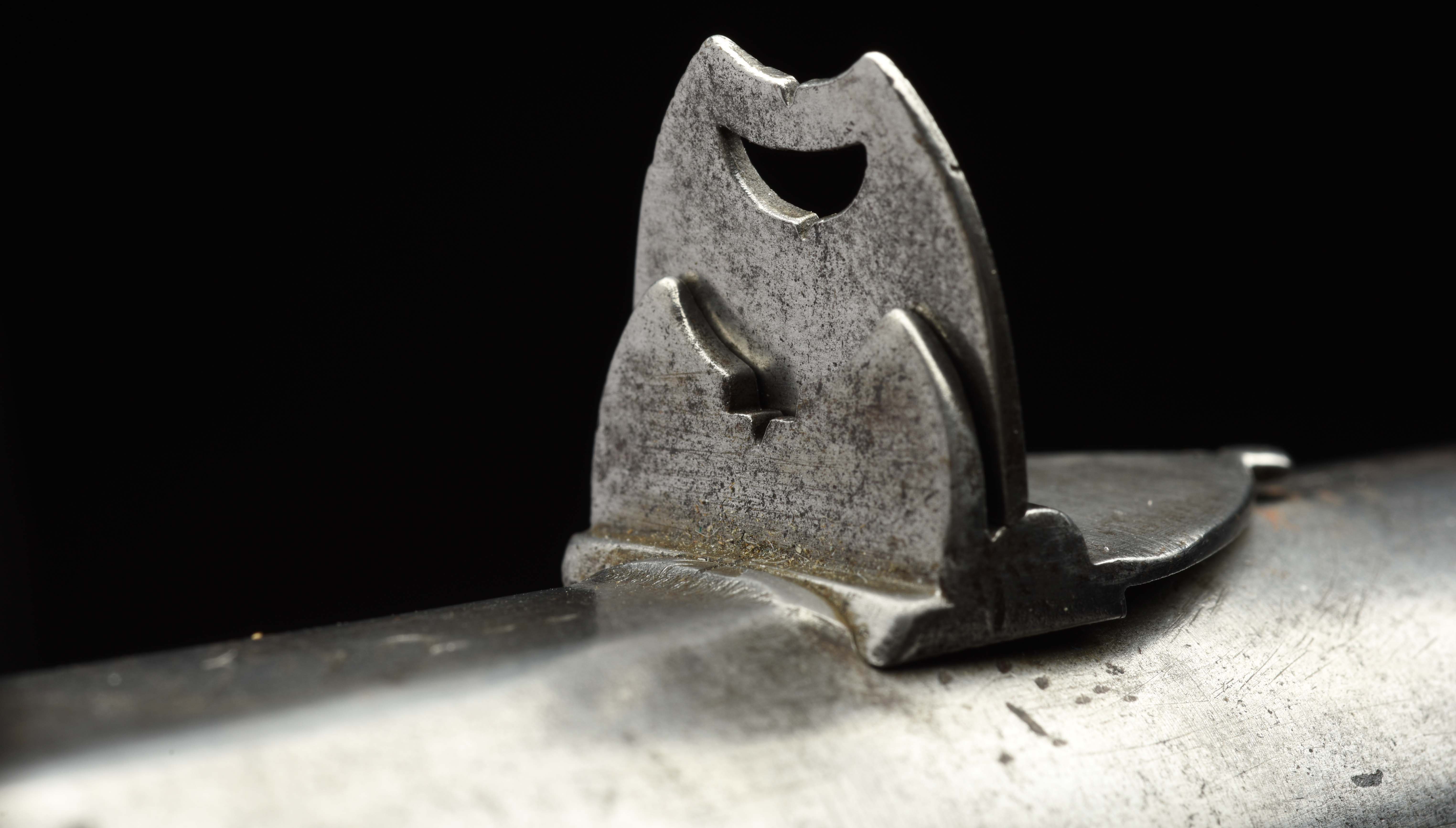
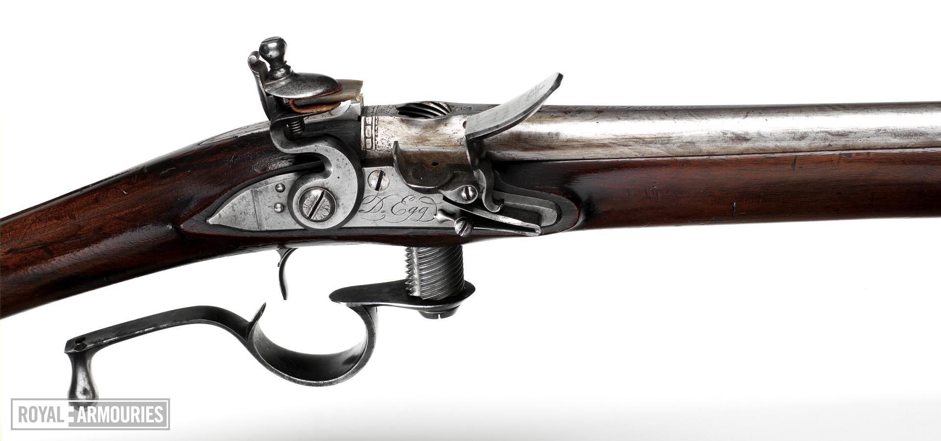
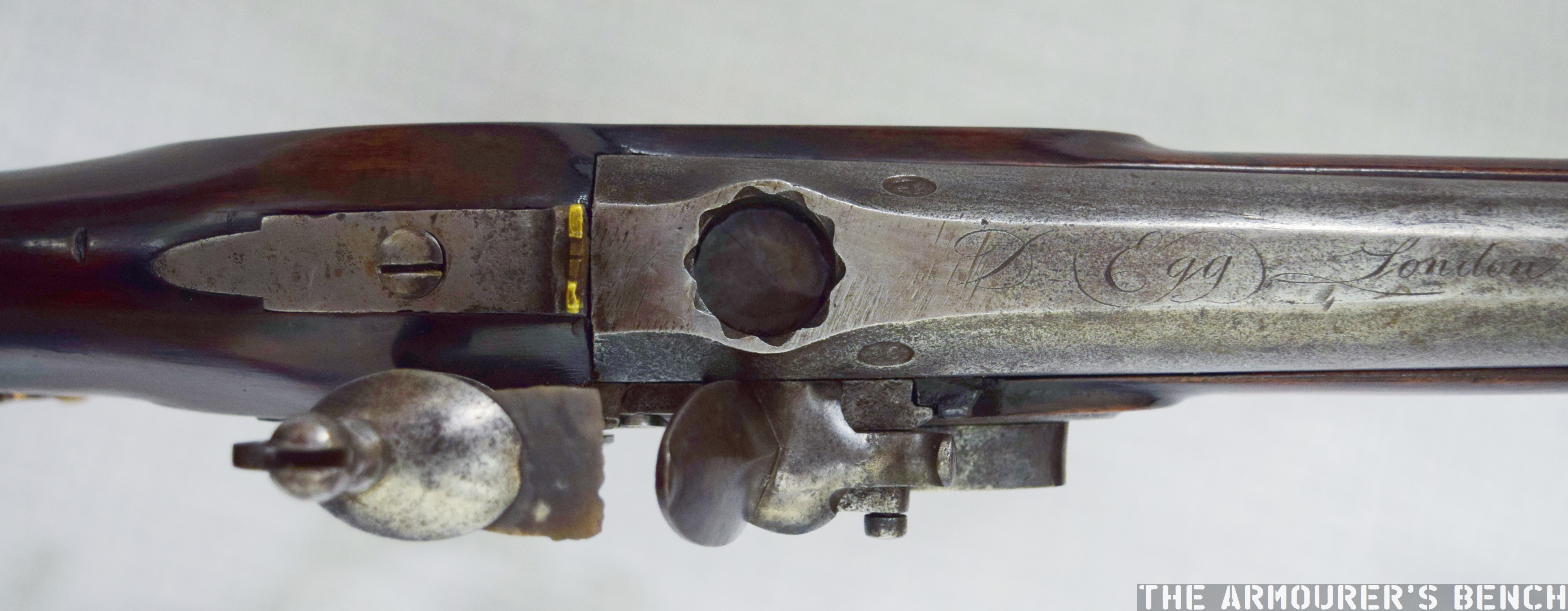
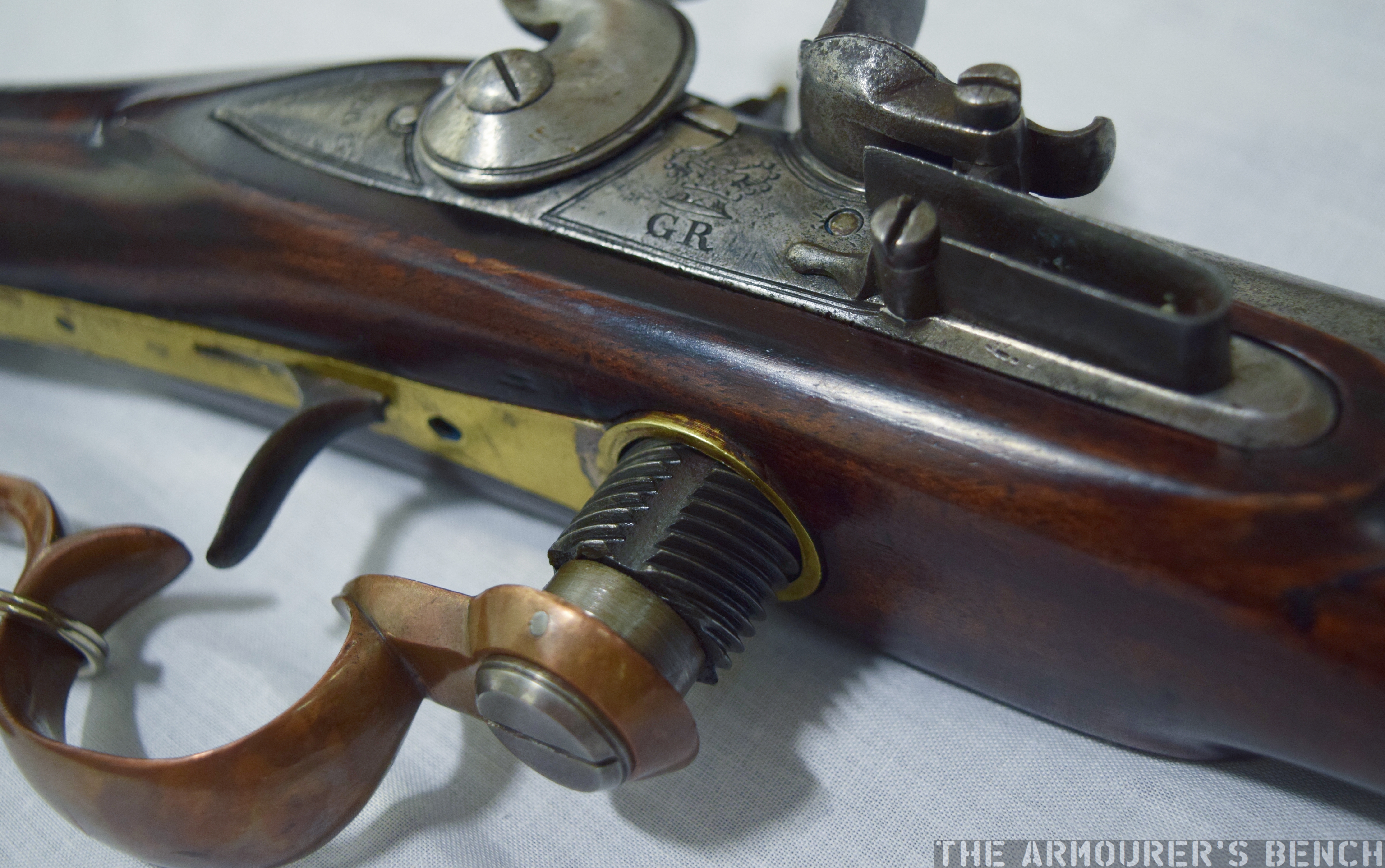
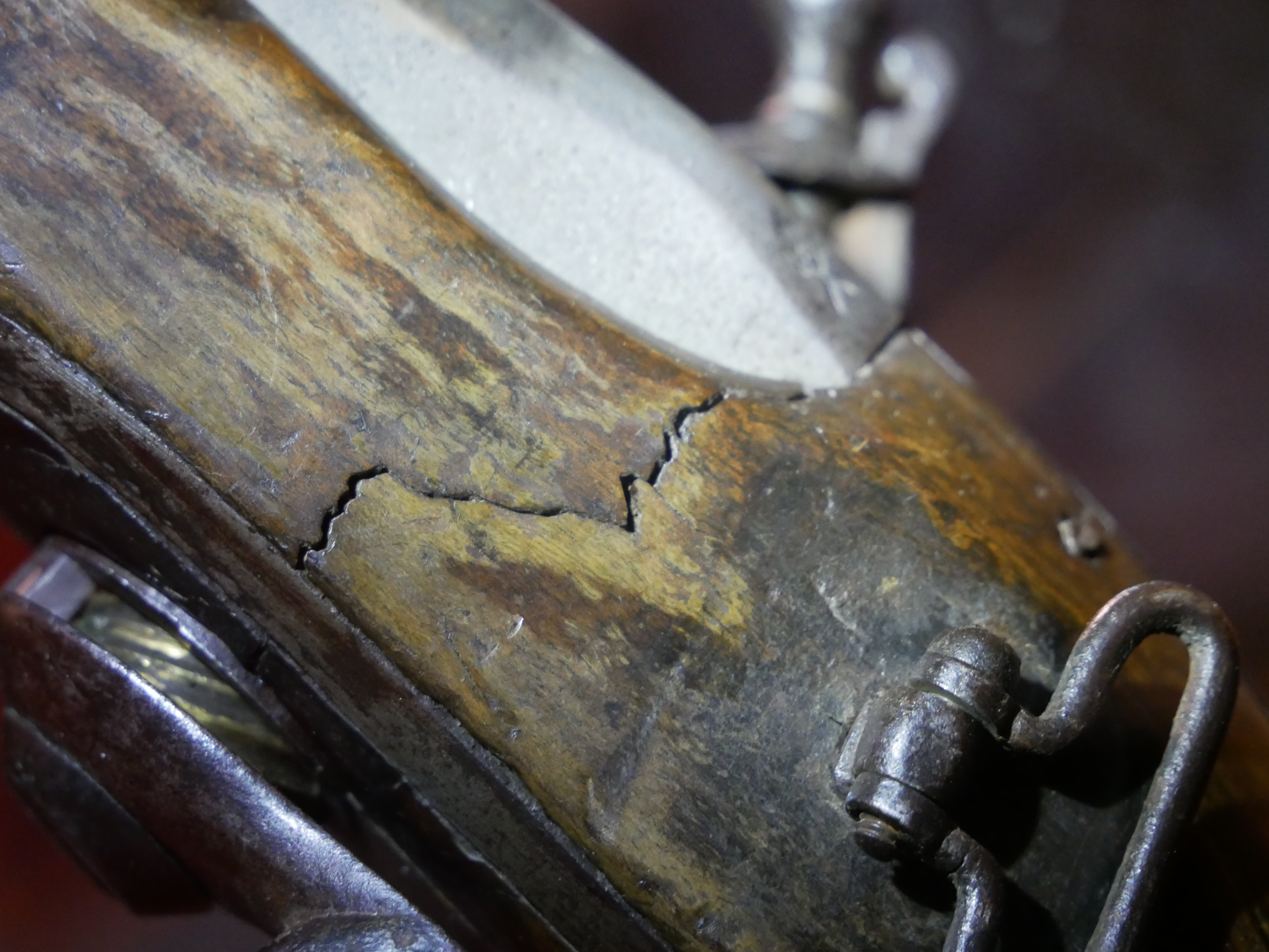
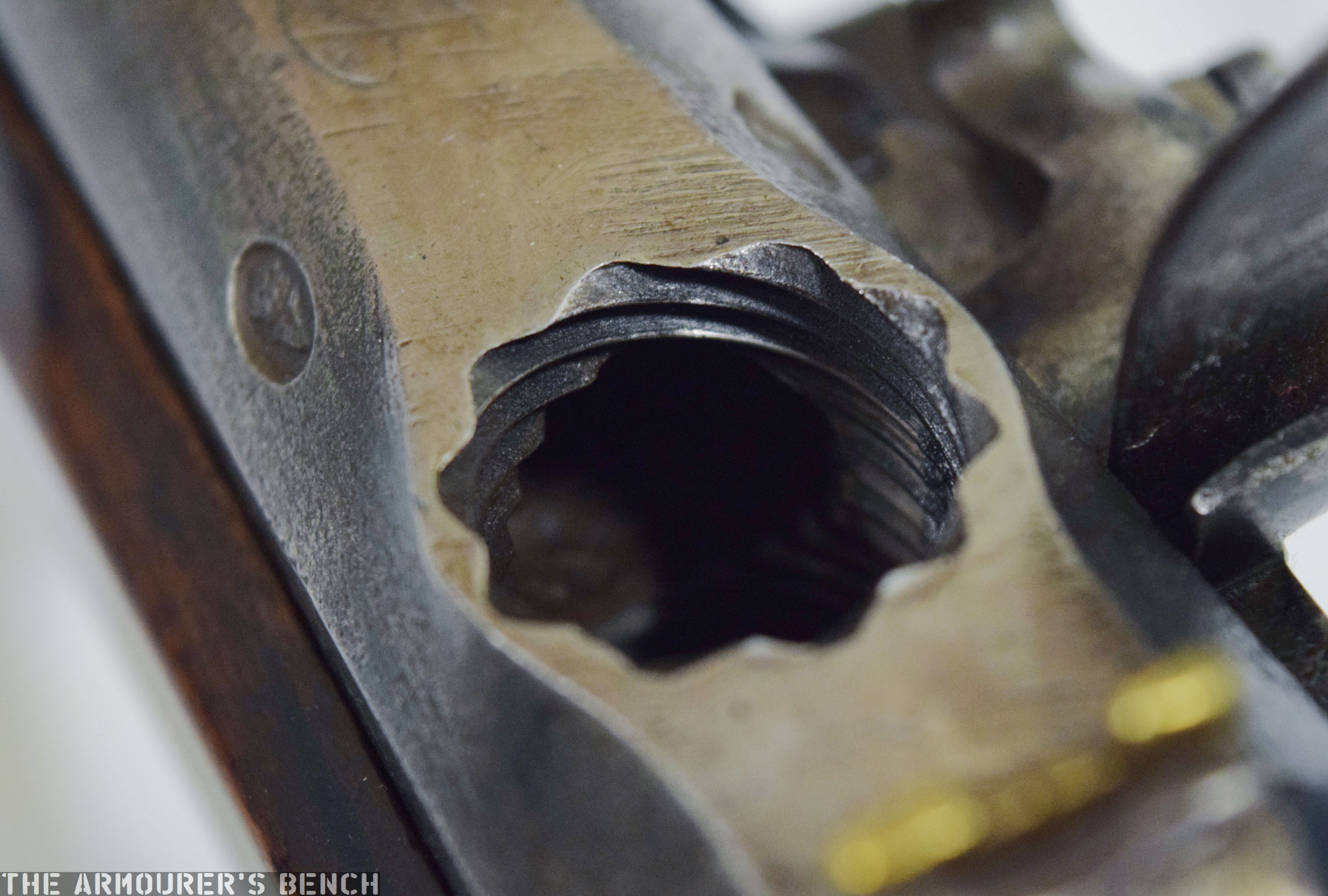
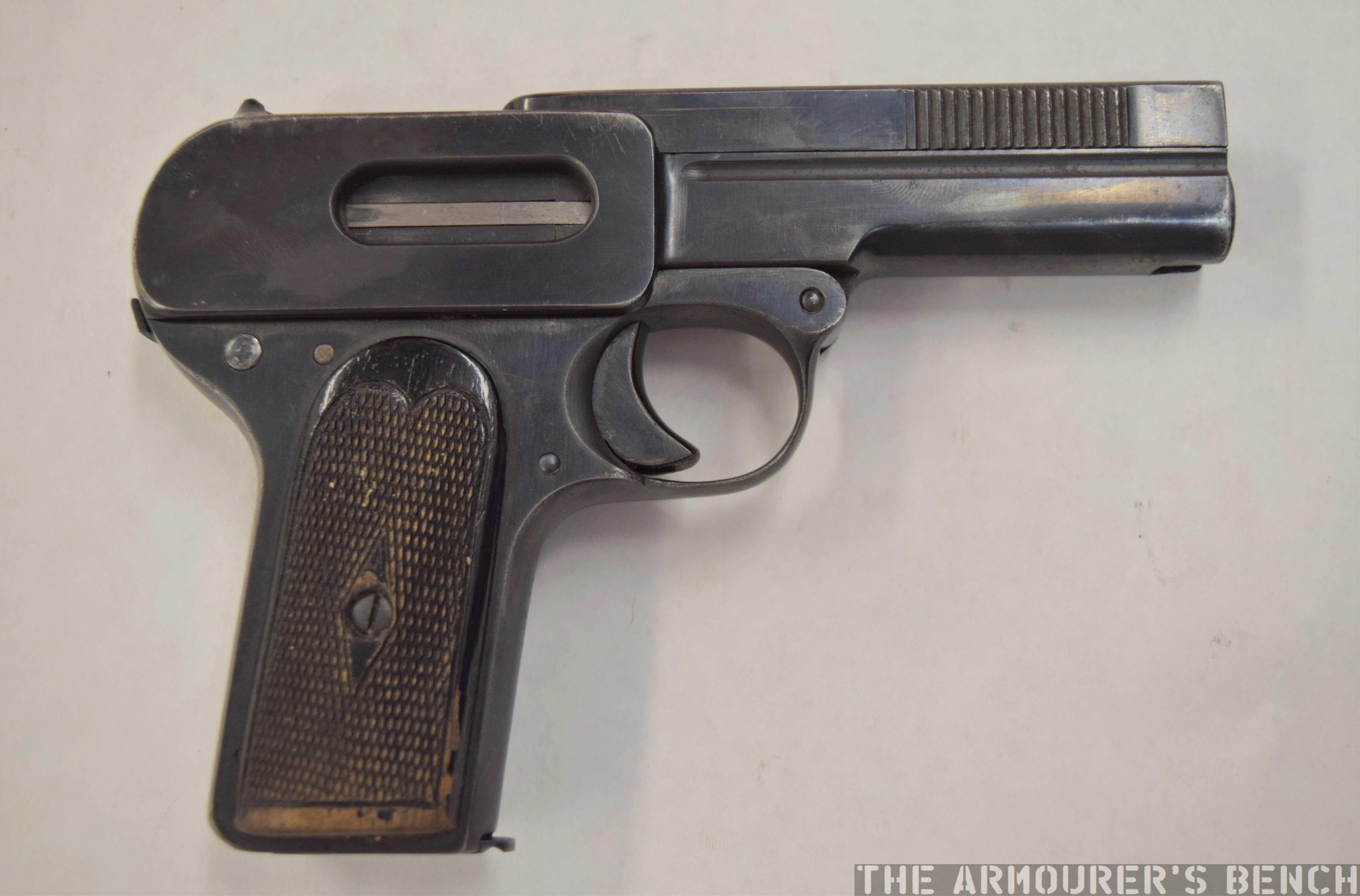


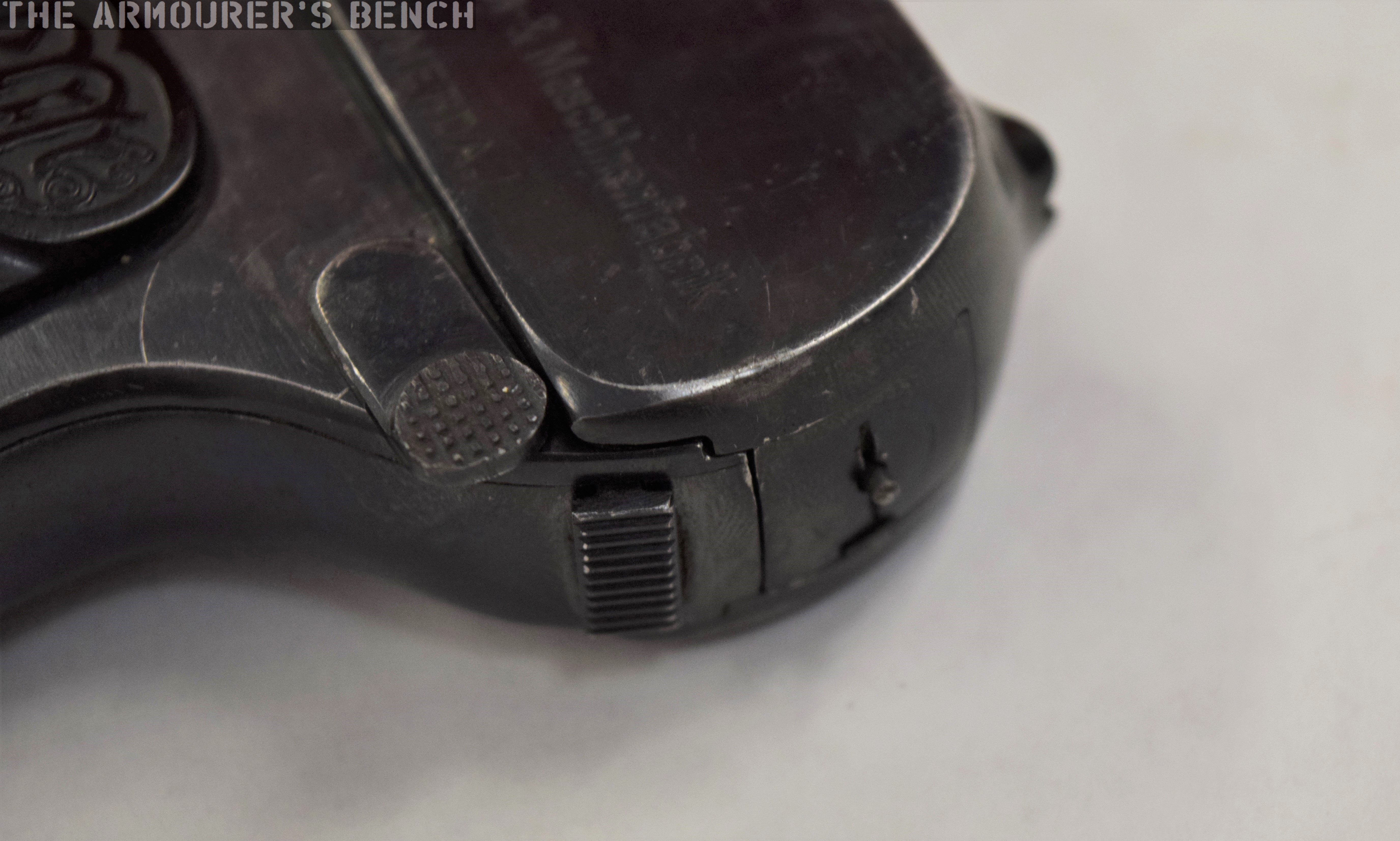
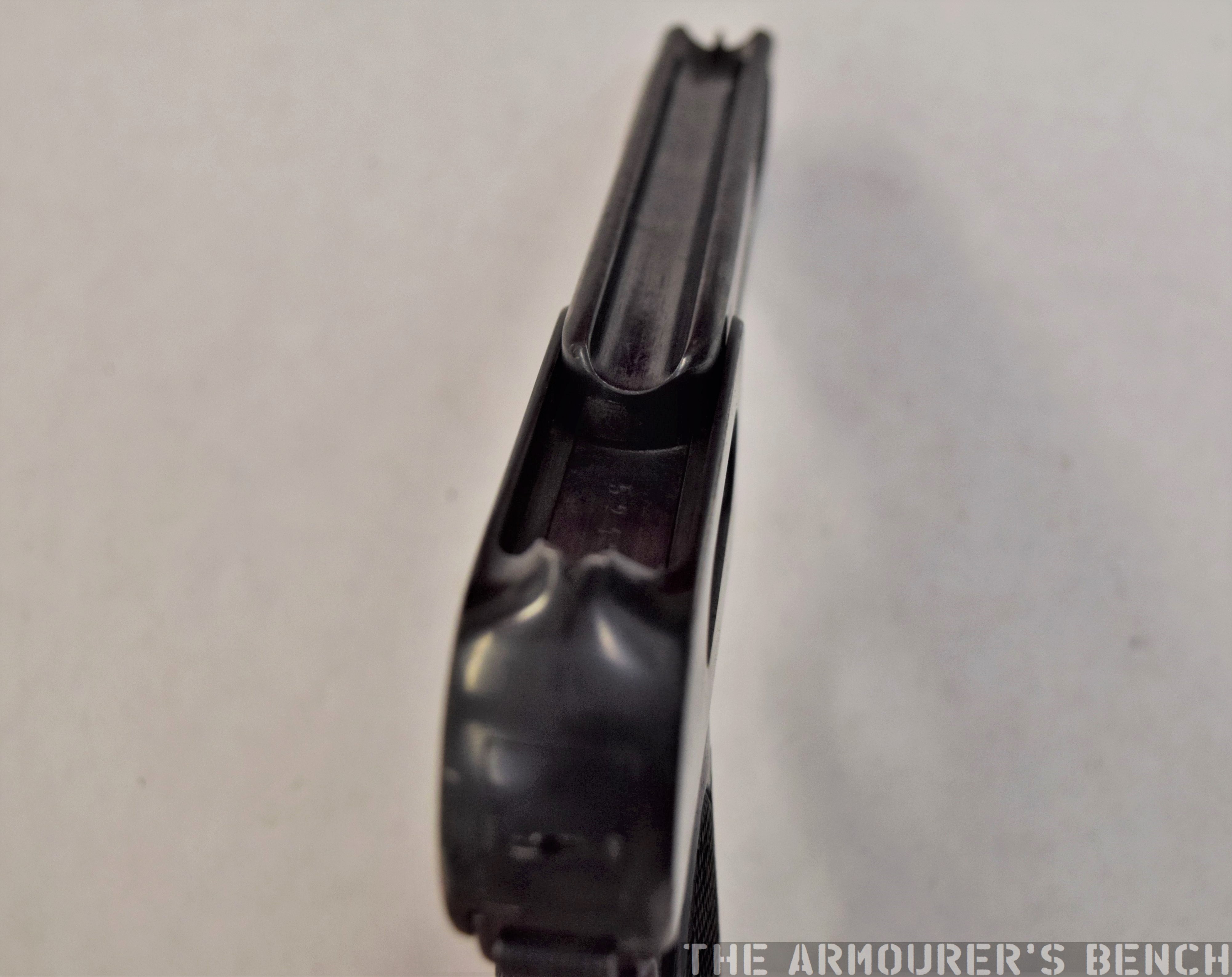
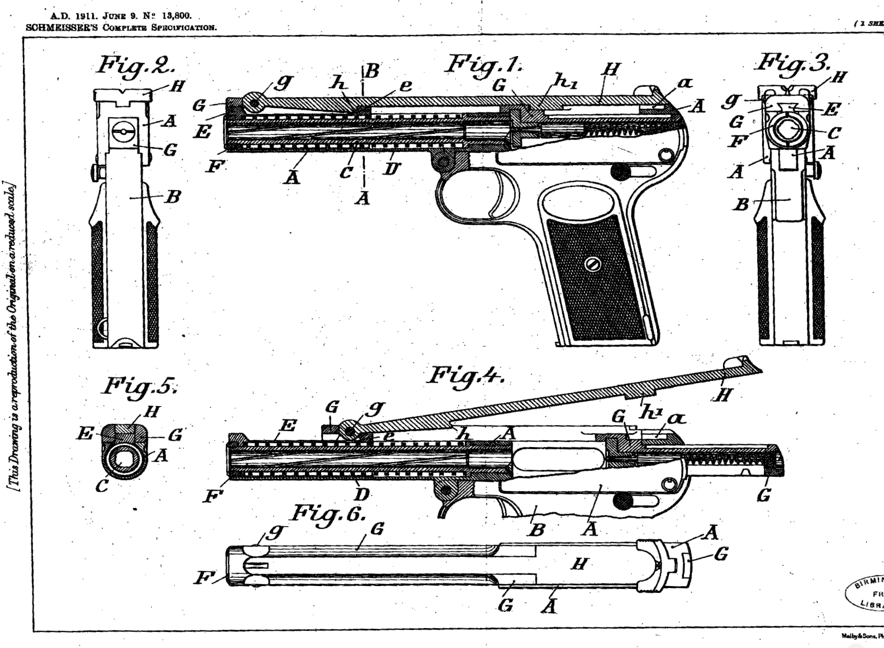
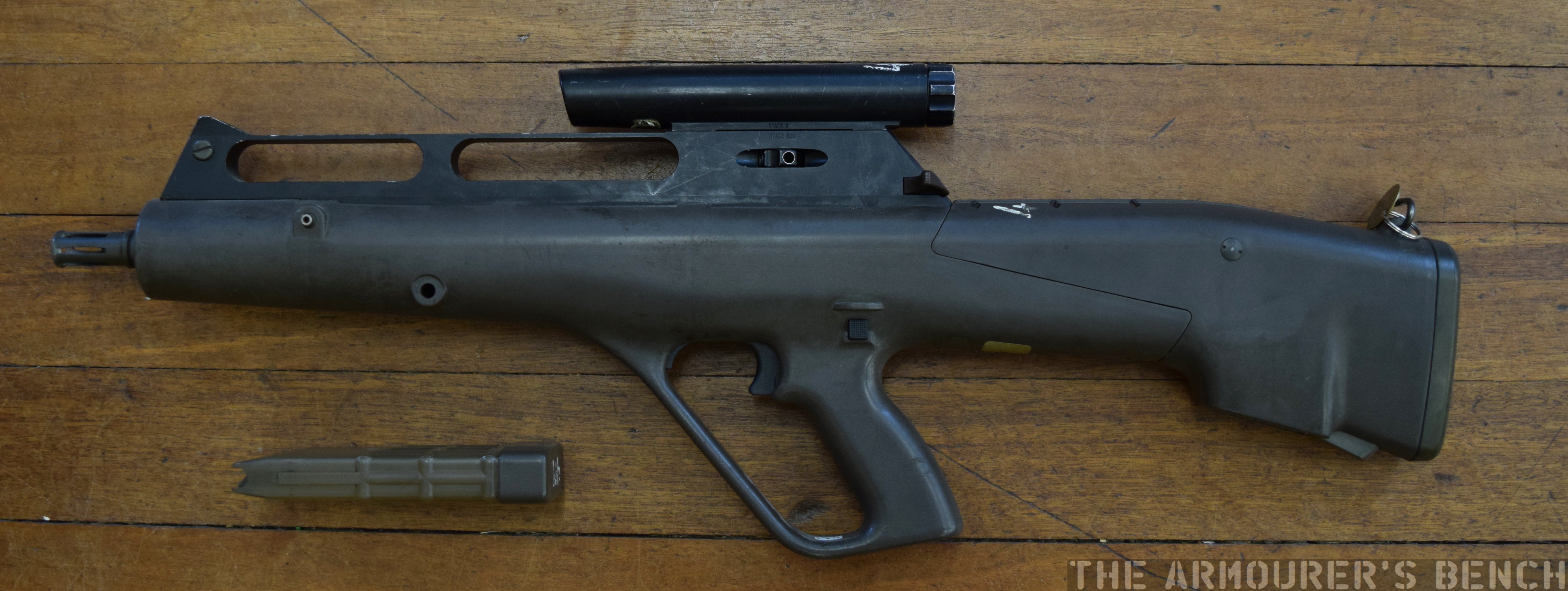
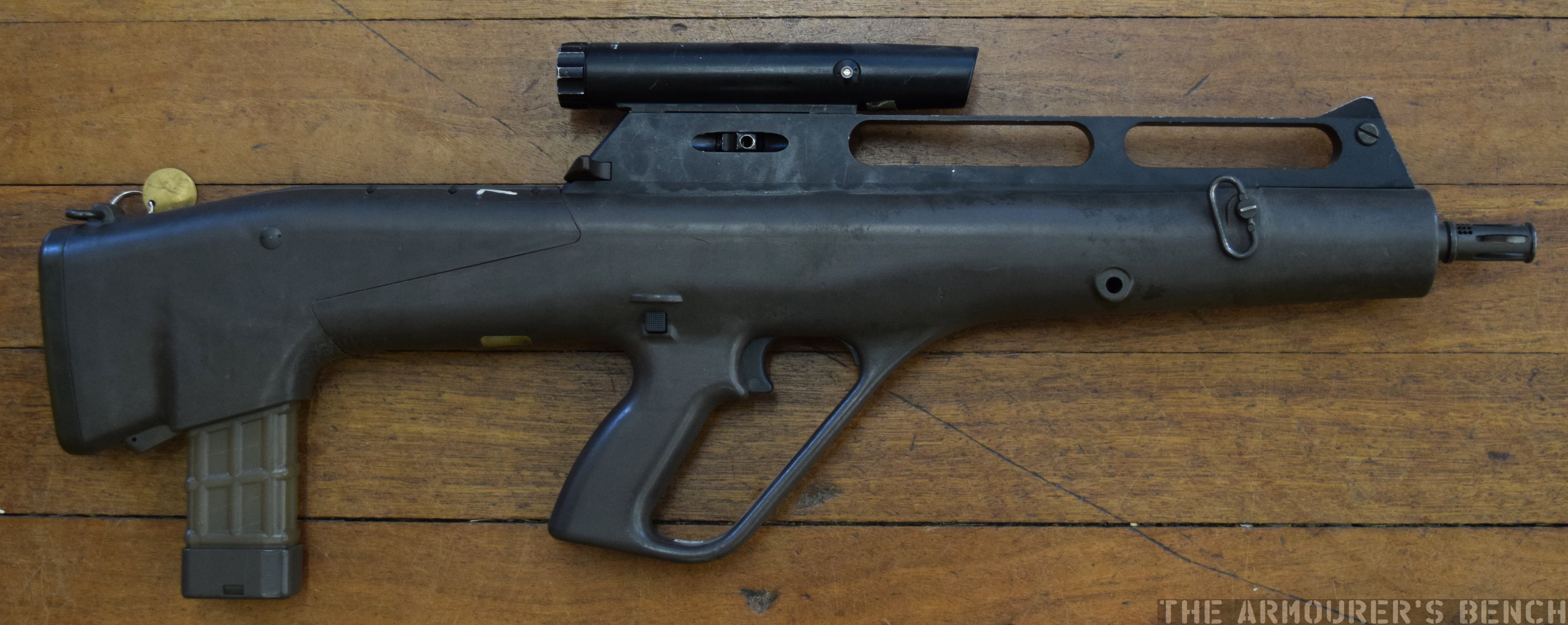 Left and right side views of the Steyr ACR, note the small AUG-style (Matthew Moss)