‘Paper Tiger’ – PIAT Scene Analysis

We return to the Projector, Infantry, Anti-Tank’s long and storied on-screen career. This time we are examining a scene from ‘Paper Tiger’ (1975). It’s an interesting film, and certainly not one you’d expect a PIAT to pop up in! David Niven plays Mr  Bradbury, a tutor to a young Japanese boy. Bradbury is a Walter Mitty-like character that regales the child with made up tales of his wartime escapades.

Early in the film Bradbury describes a battle in France in October 1944. Niven’s Character is shown to be a member of the Grenadier Guards and receivers orders to take an enemy pill box. Bradbury describes how he attacked the German position single handed. The sequence begins with what looks like a platoon making a frontal assault. 

Niven receives a call from his commanding officer and then asks his Sgt to hand him ‘the bazooka’. But it’s not a Bazooka he’s handed but a PIAT! Now it’s quite the faux pa’s to call a PIAT a Bazooka but I imagine the script called for one and the film armourer brought along British weapons to fit the action involving the Grenadier Guards. 

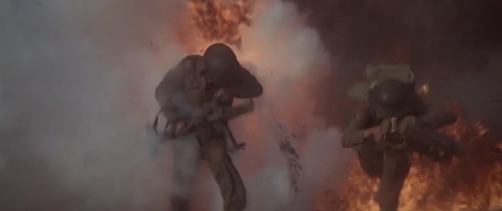
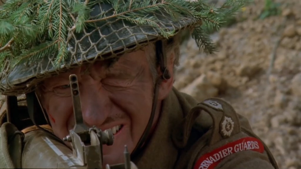
Niven’s character then charges across the ground in front of the pillbox. He takes cover in a shell crater and we can see that the bomb loaded into the tray is painted black with a yellow stripe – this denotes that its actually an inert drill round. – If we look closely inside the yellow stripe it also appears to have the words ‘drill use’ written on it. Note how far forward the bomb appears in the bomb support – this suggests that the weapon isn’t cocked and that the bomb has just been slid down onto the spigot to make it look loaded.

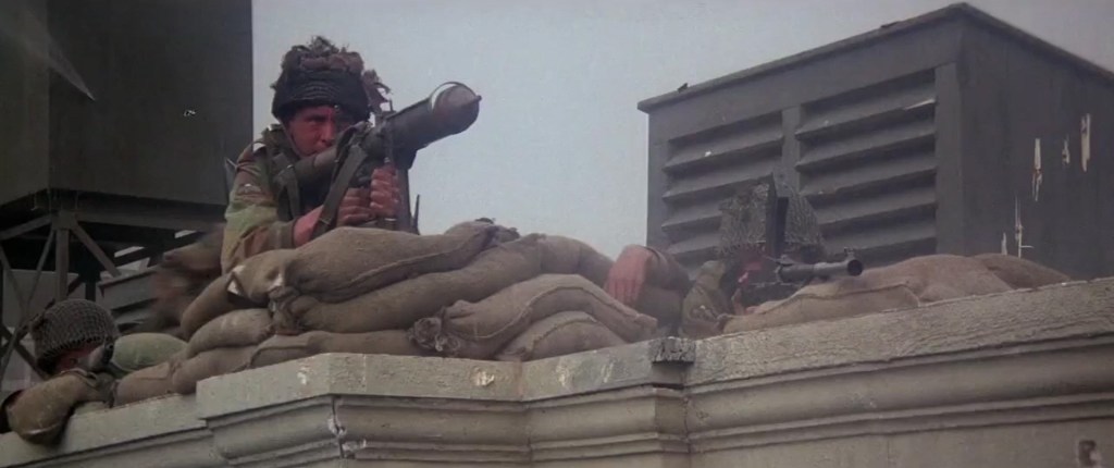
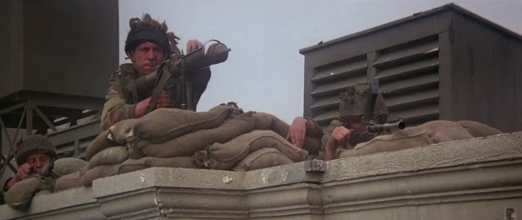
Before he can take on the pillbox a German armoured fighting vehicle (which is actually a disguised American M8 Greyhound) crests the ridge. Niven takes aim with the PIAT and knocks it out. As he aims, we can see the PIAT has the later pattern 3 aperture rear sight rather than the earlier 2 aperture. The apertures are for 50, 80 and 110 yards. The PIAT, however, is missing its webbing butt pad and gaiter cheek rest. But we can see the white indirect aiming line painted along the top of the PIAT for use in the light mortar role! 

As the Greyhounds crew bails out Niven draws his revolver and shoots the crew with a style that pastiches many war films. Leaving his PIAT Niven runs forward and we see that the spigot is forward in the bomb tray – this means he would have had to manually re-cock the weapon before firing again! As he runs we can see he has another PIAT bomb handing from his belt. I’ve never seen any contemporary photos or documents referencing this method of carrying bombs – in reality they would have been carried in a 3-bomb bomb carrier. 

He throws a No. 36 (Mills) grenade into the pillbox with perfect aim. Another funny nod to a common war movie trope! The bunker is knocked out and the enemy surrender en masse. It’s an interesting little scene, Niven as always is great and of course as a veteran of the war and an officer he would have been familiar with the PIAT. 

Check out the rest of our videos looking at on screen PIAT portrayals here.


If you enjoyed this video and article please consider supporting our work here. We have some great perks available for Patreon Supporters. You can also support us via one-time donations here. Thank you for your support!

The MB-1 ‘Genie’ – The USAF’s Unguided Air-To-Air Nuke

The MB-1/AIR-2 ‘Genie’ was the world’s first nuclear-armed air-to-air weapon and remains the most powerful missile ever deployed aboard U.S. Air Force interceptors. Developed as the Cold War began to heat up it would be carried aboard a succession of aircraft including the F-89, F-101B Voodoo, and the F-106 Delta Dart.

The MB-1 (later the AIR-2) was an air to air rocket with a 6 mile range and a 1.5 kiloton W25 nuclear warhead. It was ostensibly a tactical nuclear weapon designed to take on Soviet strategic bomber formations. The early 1950s saw the Soviet Union’s strategic bomber capability expand from the Tu-4, B-29 Superfortress copy, to include the Tupolev Tu-16 and Tu-95 and the Myasishchev M-4. These new long-range, nuclear capable bombers posed a serious threat to the continental United States. It was decided that only nuclear anti-aircraft weapons could counter the new high-flying Soviet bombers. Development began in 1954 with the project code-named “Genie” by the Air Research and Development Command.

We’ve previously looked at the Boeing BOMARC, the world’s first long-range surface to air missile, whose role was similar to the air-launched MB-1 – to engage incoming Soviet bombers. During the early 1950s, before the emergence of ICBMs, the USAF expected the main nuclear threat to the United States to come via massive attacks by Soviet long-range bombers carrying atomic bombs.

The USAF hoped that weapons like the BOMARC and the MB-1 would be able to engage and neutralise large soviet formations before they reached their targets. This would be achieved by USAF interceptors scrambled to meet the incoming Soviet aircraft, the interceptors would move into engagement range and launch their MB-1 missiles, turning away to avoid the blast. The Genie would detonate inside or near the Soviet formations breaking up their attack. For this role, attacking massed enemy aircraft, the Genie certainly appears to be an efficient weapon concept. However, like the BOMARC it quickly became obsolete as the Soviets moved away from strategic bomber aircraft and embraced long-range intercontinental ballistic missiles.

BOMARC Site No. 1 at McGuire Air Force Base (USAF)

Development of the MB-1 was carried out by the Douglas Aircraft Company. Physically, the plump-looking air-to-air nuclear rocket was 9ft 2in long and 17.5in in diameter, weighing in at just over 820lbs (372kg). The weapon had four fins, which spanned over 3 feet, these deployed once launched and helped to stabilise the Genie’s flight.

The Genie carried a 1.5-kiloton W-25 nuclear warhead and was powered by a solid-fuel rocket engine developed by Thiokol. It could reach speeds up to Mach 3.3 and travel just over 6 miles before detonating. It’s effective blast radius was estimated to be just short of 1,000 feet (300m), the Genie relied upon this area effect as guidance systems small enough to be fitted to a missile were in their infancy, as a result the Genie was essentially an unguided rocket with no onboard guidance. 

An Northrop F-89J has the distinction of being the only aircraft to fire a live MB-1 Genie during the Operation Plumbbob tests on 19th July, 1957. The F-89 was flown by Captain Eric W. Hutchison, with Captain Alfred C. Barbee acting as Radar Intercept Officer. They launched the Genie at around 18,500 feet, the nuclear-tipped Genie accelerated to Mach 3 and travelled 2.6 miles in less than 5 seconds. While operationally the weapon would have detonated by a time-delay fuse the Plumbbob detonation was triggered by a signal from the ground.

The F-89, flown by Captain Eric W. Hutchison, firing a live MB-1 during Operation Plumbbob’s Test Shot John, 1957 (National Nuclear Security Administration)

Test shot John was a form of controlled human testing, with not only those on the ground, beneath the blast tested for radiation dose sizes but also the crews of the aircraft that launched the rocket. This contemporary film about the test notes that “neutron and gamma doses for the three crews did not exceed 5 Reps and 3 Roentgens respectively.

A later report noted:

“Neutron and gamma radiation dosages received by the crew members were less than had been predicted. To some extent this may he attributed to the effect of aircraft shielding. which was not utilized in the theoretical predictions. No crew member received more than 5 Reps neutron and 3r gamma during his participation. The experiment proved that the MB-1 air-to-air rocket can be successfully launched by the F-89 aircraft at 19,000 feet MSL with a radiation dose to the delivery crew within acceptable limits.”

The yield of the explosion was estimated to have been 1.7 kilotons. 18,500 feet below, at ground zero, five USAF officers and a photographer volunteered to stand under the blast to prove that the weapon was safe for use over populated areas. The radiation doses received by the F-89 crew and the men on the ground were reportedly small.

An F-106 Delta Dart aircraft after firing an ATR-2A missile over a range. The aircraft is assigned to the 194th Fighter Interceptor Squadron, California Air National Guard (USAF)

The MB-1 became the primary air to air weapon of the F-106 Delta Dart, this footage includes and illustration showing how the MB-1 was deployed from the F-106 as well as some of the live missile tests with inert missiles during the development of the Delta Dart’s launch system for the Genie.

Douglas built more than 1,000 Genie rockets before terminating production in 1962. In June 1963, the MB-1 Genie rockets were re-designated in the AIR-2 and later the ATR-2A. The USAF’s operational deployment of the Genie ended in late 1980s with the retirement of the last F-106 Delta Darts. The Genie’s other operator, the Royal Canadian Air Force, continued to operate the Genie aboard until 1984.

Bibliography:

OPERATION PLUMBBOB, Technical Summary of MiIitary Effects, 1962, Defense Atomic Support Agency, (source)

‘MB-1 Documentary’, Douglas Aircraft Company via US National Archives, (source)

‘Five Men at Atomic Ground Zero’ Operation Plumbbob Test Shot John footage, Atomic Central, (source)

‘The F102A – F106A Annual Review 1957’, technical review of the Delta Dagger, USAF via San Diego Air and Space Museum Archives, (source)

’19 JULY 1957 – FIVE AT GROUND ZERO’, CTBTO, (source)


If you enjoyed these videos and this article please consider supporting our work here. We have some great perks available for Patreon Supporters. You can also support us via one-time donations here. Thank you for your support!

Bring Up The PIAT Pt.II

So you may have seen our earlier video looking at the portrayal of PIATs in the 1978 classic A Bridge Too Far! If not check it out.

When I think of Richard Attenborough’s all-star war epic telling the story of Operation Market Garden, I immediately think of the iconic ‘BRING UP THE PIAT’ scene where Anthony Hopkins playing Colonel John Frost commanding 2 PARA calls for the Projector, Infantry, Anti-Tank to take out a marauding ‘Panther’.

But this isn’t the only scene from the film depicting the PIAT! In this video we’ll look at a couple of the other scenes showing the PIAT in action.

We first see the PIAT during the scene when the Guards Armoured Division’s spearhead meets heavy german resistance. Michael Caine’s Sherman’s get a pasting from some Pak 40s. The British infantry deploys and we see a cornucopia of kit ranging from Brens to Vickers to an M2 Browning. But blink and you’ll miss them a pair of PIAT teams also ‘bring up the PIAT’. A two man team can be seen moving forward, the No.1 carrying the PIAT and the No.2 carrying a 3 round bomb carrier, sadly killed by enemy fire.

The second scene in which we see the PIAT finally get to work on some German armoured fighting vehicles is during Gräbner’s attack over the bridge. As the PARAs at the Bridge prepare for the attack we see 2 or 3 PIAT positions get ready – loading bombs into their bomb support trays. One PIAT No.1  can be seen slotting the rear of a PIAT bomb into the projectile guide plates to hold the bomb in place – very authentic.

As the column crosses the Bridge Frost orders his men to open fire, Brens, Stens, Rifle No.4s and PIATs open up and the column is stopped in its tracks. During the scene we see a number of PIAT’s fire and knock out SS vehicles. One PIAT No.2 is hit by enemy fire. The first PIAT round fired hits a lead German vehicle causing it to halt, the second flips a Kubelwagen. We then see a No.2 two load a fresh bomb into the bomb support tray – with a tap to make sure its properly in place. We get a great show of the PIAT firing from the front. It’s worth noting that the PIAT doesn’t recock and the spigot is still seen in the bomb tray just before the camera cuts away. Meaning that that PIAT No.1 will have to recock his weapon before he can fire again!

It’s worth remembering without the ‘Bring Up The PIAT’ scene making a point of naming the weapon, most people would never have known what this unusual weapon that dealt so much damage in the earlier scene was! Of course the attack wasn’t stopped by PIATs alone, there were also airborne anti-tank guns, which the film doesn’t show.

Another little titbit of information I learnt since the first ‘Bring Up The PIAT’ video, thanks to my friend Robbie of RM Military History [check out his channel], is that the PIAT was fired in most of these scenes by one of the film’s armourer Bill Aylmore. The information comes from After the Battle – The Battle of Arnhem – War Film: A Bridge Too Far which describes him as formerly a sergeant with the 50th Regt. – which might be a reference to the Queen’s Own Royal West Kent Regiment. The book goes on to say that “Aylmore excelled himself during the filming of the battle on the bridge by being the ace shot with the PIAT. During all the various takes he was able to put the bomb exactly where the director wanted it and where it coincided with the special effects explosions.” – Good shooting indeed!

Check out more PIAT scene analysis videos here.


If you enjoyed these videos and this article please consider supporting our work here. We have some great perks available for Patreon Supporters. You can also support us via one-time donations here. Thank you for your support!

Cold War British Vehicles – Anglesey Transport Museum

Late last summer we visited the Anglesey Transport Museum in North Wales. They had a great collection of classic and vintage cars and bikes and most interestingly they had a little collection of British military vehicles.

They had a number of trucks and special purpose vehicles from the Royal Engineers, REME and RLC and even a Green Goddess Fire Engine. They also had a couple of pretty cool Cold War British Army armoured personnel carriers.

Alvis Saracen

Alvis Saracen (Matthew Moss)

The Saracen was a six-wheeled armoured personnel carrier (APC) built by Alvis. It entered service in 1952 and was used extensively in Malaya and Northern Ireland. The Saracen could carry an 8 man section along with its 2 man crew. It had a 160HP Rolls Royce engine and depending on when during its service life its turret could be mounted with a .30 calibre M1919A4 or an L37 vehicle-mounted general purpose machine gun.

Humber Pig

Humber Pig (Matthew Moss)

Another APC which was in service alongside the Saracen, the ‘Truck, Armoured, 1 Ton, 4×4’, better known as the Humber Pig. Based on a truck chassis, it had a 120HP 6 cylinder engine and room for 6 men on the benches in the back. It could be mounted with an L4 Bren gun. It saw extensive use in Northern Ireland during operation Banner and was in service from 1956 through to the early 90s.

Daimler Ferret Mk1 Scout Car

Daimler Ferret (Matthew Moss)

Next to the Pig in the collection was a Mk1 Daimler Ferret scout car. Fitted out with an M1919A4 and six forward-firing grenade launchers – for smoke grenades. The later Mk2 had a turret but the Mk1 made use of its low profile. This one has its canvas cover over the fighting compartment. The 4×4 Ferret was powered by a 130HP Rolls Royce B60 straight six. Perfect little run-around to do the shopping in.

On the top of the hull is the pintle mounted Browning M1919A4 machine gun. This would have been operated by the Ferret’s commander. We can see the mount allows it to be aimed and fired from somewhat inside the hull. The Ferret entered service in the early 1950s and remained in use into the late 1980s/early 1990s. Just short of 4,500 Ferrets were manufactured.

Bofors QF 40mm Mk1

QF 40mm Mk1 (Matthew Moss)

At the centre of the military vehicle collection was a QF 40mm Mk1, better known as a Bofors. Both land and naval versions of the Bofors were used during the Second World War and after. Capable of firing 120 40mm shells per minute, it was normally manned by a four man crew. It filled the British army’s light Anti-Aircraft gun role and remained in service well into the 1980s.

We can see the gun’s huge recoil spring and to the rear of the gun is a case deflector which connected with a trough which channels the spent cases down below the gun. The gun still has most of its controls and traverse and elevation crank handles in place. On top of the gun are the huge guides for the four-round clips of 40mm shells.

Find out more about the museum here.


If you enjoyed these videos and this article please consider supporting our work here. We have some great perks available for Patreon Supporters. You can also support us via one-time donations here. Thank you for your support!


John Browning’s 1895 Slide-Action Prototype

By 1895 Winchester had been considering a slide-action rifle for some time, in 1882 William Mason had begun work on one (US Patent #278987) to counter Colt’s slide-action Lightning only to drop it. Finally in 1890, Winchester introduced a slide-action .22 calibre rifle developed by John Browning. The Model 1890 became extremely popular.

Between 1887 and 1895 Browning patented four slide-action rifle designs. The first of these, US patent #367336, was granted in July 1887, this was followed in 1888 by US patent #385238. In September 1890, the Browning brothers were granted US patent #436965, which along with the previous 1888 patent protected what became the Model 1890. Three years later Winchester introduced the Model 1893 pump action shotgun, that would eventually evolve into the famous Winchester Model 1897.

Right-side close up of the rifle with its action open (Matthew Moss)

Finally, April 1895, Browning filed a patent for a design for a .30 calibre rifle which was granted in September 1895 (US patent #545672) This patent covers the rifle we’re examining here. The rifle itself is a slide or pump action in long barrelled configuration which Winchester described as a ‘Musket’.

The September 1895 slide-action design was purchased by Winchester but like so many other Browning designs, it never entered production and Winchester purchased the design purely to secure it and prevent other rival manufacturers picking it up. Winchester instead went with a lever-action design, patented in November 1895 (US #549345), which became the famous Winchester Model 1895.

A left-side view of the rifle’s receiver with Browning’s patent overlaid (Matthew Moss)

The September 1895 slide or pump-action rifle design had a laterally camming locking breechblock. As we can see, externally Browning’s toolroom prototype looks somewhat similar to the contemporary Winchester Model 1895, with a single-stack integrated box magazine but with a pump sleeve rather than a lever. 

An action-bar connects the slide/pump to the front of the breechblock/bolt carrieron the right-hand side of the rifle. The slide handle itself is made of a U-shaped piece of metal which wraps around the rifle’s forend. The slide has been roughly cross hatched to improve grip. There is a channel cut into the furniture for the action arm’s attachment point to travel. The slide is attached to the arm by a pair of screws.

A close up of the rifle’s slide/pump handle (Matthew Moss)

However, Browning developed this prototype to allow loading of the magazine from below rather than through the top of the receiver. He added a hinged floor plate, with a spring loaded follower, that allowed loose rounds to be dropped into the magazine and then closed.

As we open the magazine, hinging the cover plate down, we see the carrier flip down against the plate to allow loading. The rifle was designed to be loaded from below with the bolt forward.

Browning’s September 1895 patent (US Patent Office)

In the patent description Browning explained that his aim was to improve breech-loading box-magazine firearms by designing:  

“…a simple, compact, strong, highly effective, and safe gun, containing comparatively few parts and constructed with particular reference to provision for charging the box-magazine with cartridges from the bottom of the frame of the arm while the breech-bolt is in its closed position, so that the arm may be charged without operating its action mechanism or disturbing the cartridge in the gun-barrel, if one is there.”

Browning’s September 1895 patent (US Patent Office)

From the original patent drawings we can see the flat spring which acted on the carrier running below the barrel, ahead of the magazine. Inside the magazine are a pair of what Browning refers to as ‘spring fingers’ these act on the cartridges inside the magazine and keep them properly aligned, seen here in Fig.7 of the patent. In Fig.8 we can see what Browning calls a ‘box-like guideway’ which guide the rims of the cartridges, “preventing the cartridges from being displaced while being fed upwards.”

The rifle’s breechblock locked into a recess in the left side of the receiver, tilting at an angle with the rear of the breechblock canting to the left. When the pump handle was pulled rearwards the breechblock cammed laterally to unlock the action, extracted and ejected any spent casing and when the slide/pump was returned forward a new cartridge was picked up from the magazine, chambered the breechblock locked again ready to fire. The rifle’s hammer was cocked by the rearward movement of the breechblock.

A left-side view of the rifle with its action open, note the complex machining on the rear of the breech bolt (Matthew Moss)

Externally, the slide-action’s receiver looks similar to that of the production Model 1895 but internally they are very different. The action is certainly less open than the Model 1895’s but the lateral locking mechanism is less robust. Additionally, with no lever, as in the Model 1895, the slide-action rifle lacks the safety mechanism which prevents the action from opening accidentally.

A view inside the open magazine with the floorplate hinged open (Matthew Moss)

The model is in the white and while externally the machining and tool work is very neat, inside the action we can see where the cuts in the receiver wall have been more crudely made. In terms of design, the slide-action prototype was certainly simpler and had fewer working parts than the Model 1895 lever-action.

Winchester purchased the .30 calibre slide-action design but never produced it, it is believed that only Browning’s prototype was built to prove the concept. The prototype was part of Winchester’s collection and may now be found at the Cody Firearms Museum.

Check out our earlier videos on Browning’s lever-action box magazine-fed prototype and his en bloc clip-fed prototype.


If you enjoyed the video and this article please consider supporting our work here. We have some great perks available for Patreon Supporters. You can also support us via one-time donations here.


Bibliography:

‘Box Magazine Bolt Gun’ J.M. Browning, US Patent #545672, 3 Sept. 1895 (source)

‘Box Magazine Firearm’, J.M. Browning, US Patent #549345, 5 Nov. 1895 (source)

John M Browning: American Gunmaker, J. Browning & C. Gentry (1964)

Winchester Repeating Arms Company, H. Houze, (2004)

STEN Magazine Loaders

While the ongoing Coronavirus pandemic has prevented some archival research I had planned which would have informed much of the STEN series, our good friend Richard at the Vickers Machine Gun Collection and Research Association, has come to our aid and we’re able to cover some of the loading accessories developed for the Sten’s magazines.

As we know the Sten uses a 32-round double stack, single feed magazine which can trace its origins back through the Lanchester Machine Carbine to the Haenel MP28,II’s magazine designed by Hugo Schmeisser [patented in 1931].

Sten Magazine, inert 9x19mm rounds and MkII and MkIV magazine fillers

The nature of the single feed makes the magazine difficult to load by hand with the last few rounds very hard to insert. So a series of four marks of ‘magazine fillers’ were developed. These are described in the British Army’s official List of Changes in February 1943.

The MkI is described as consisting of “a lever mounted on a short case which conforms to the shape of the magazine. It is hand operated, the loading lever being given a rocking motion during filling. The MKI slipped over the top of a magazine with a rivetted spring tab which indexed into a notch in the front of the Sten mag.

A cutaway showing the MkII filler

The MkII is very similar but simplified by having the spring catch mounted on the rear instead of the side and engaged a “small rectangular slot on the magazine”. The rear of the spring is turned up slightly to allow the user to remove its from the magazine.

The MkIII, which is possibly the rarest of the fillers, is described as:

“hand operated but of different design from the MkI and MkII. It consists essentially of a spring loaded vertical plunger which is attached externally to a case, the latter to assemble on the magazine. There is no retaining catch. It comprises the following parts:

Case. Is a rectangular shaped steel pressing with a tube of rectangular section welded thereto. The latter, which houses the plunger and spring, has a hole trilled at the lower end to accommodate a pin which restricts the amount of movement of the plunger and acts as a stop for the compressing spring.

Plunger, loading. Is made of two laminated steel strips welded together the top part of which is set to form a handle. The body of the plunger is slotted to accommodate the compression spring. The top part is splayed to form a suitable contact with the cartridge.”

List of Changes, Feb. 1943
Sten accessories including a sling and a MkII magazine filler

The other more common filler is the MkIV. Which is a much simpler design with a loading lever mounted on top of a clip which is attached to the rear of the magazine body and retained by a spring similar to that of the MkII.

Rich has very kindly demonstrated the use of the two most common fillers – the MkII and the simpler MkIV. It takes Rich just under 2 minutes to load that magazine, but he was doing his best to show various angles and unlike a British soldier during the war he hasn’t regularly loaded magazines with one of these fillers either. Despite that the clip gives a good idea of how fast you could load a mag once you’re in the groove.

With the MkIV filler Rich was able to load the mag in about 1 minute 15 seconds, the stability of resting the base of the mag on the table helped with the MkIV’s simpler design.

Manual diagram showing both the MkII and MkVI

Also, as a follow on to our previous episode looking at the Sterling Submachine Gun’s magazine Rich has also demonstrated the loading of a Sterling mag to its 34 round capacity. No magazine filler needed with George Patchett’s double-stack, double feed magazine.

Massive thanks to Richard for taking the time to film the clips used in the video. please do go and check out Richard’s channel and www.vickersmg.org.uk.


If you enjoyed the video and this article please consider supporting our work here. We have some great perks available for Patreon Supporters. You can also support us via one-time donations here.

XF-87 Blackhawk

Development of the XF-87 began at Curtiss-Wright in 1946, it would eventually be intended to be an all-weather interceptor. The Blackhawk was developed from an earlier ground attack, tactical bomber design, the XA-43. The Blackhawk was a response to the initial specification for a jet-powered night fighter, capable of speeds up to 530 mph, issued by the US Army Air Force in August 1945.

A number of companies responded including Bell Aircraft, Consolidated-Vultee, Douglas Aircraft, Northrop, Goodyear and Curtiss-Wright. The US Army Air Force down-selected Northrop’s design – then known as the N-24 and the Curtiss-Wright design- known as the Model 29A.

Curtiss-Wright XF-87 (US Air Force)

The XP-87 had a two-man crew seated side-by-side and was powered by two pairs of Westinghouse XJ34-WE-7 turbojet engines mounted on the wings. In comparison to the sleeker Northrop design, the Blackhawk was a slightly larger, bulkier and heavier aircraft with a straight wing profile. The XJ34-WE-7 turbojets only provided 12,000 lbf and Curtiss-Wright’s test pilot B. Lee Miller described performance in initial tests as sluggish. The Blackhawk’s armament was to consist of four 20mm cannons mounted in a nose turret.

The US Army Air Force designated the Curtiss-Wright jet the XP-87, while Northrop’s N-24 became the XP-89 and full-scale models of both were ordered.

The Curtis XP-87 (Curtiss-Wright, courtesy of Mark Lane)

In June 1948 the newly formed US Air Force re-designated fighters from P to F and the XP-87 became the XF-87 when prototypes were ordered. The XF-87 made its first flight in March 1948. During subsequent flight evaluations in October 1948, the Northrop XF-89 was found to be faster than the XF-87 and the US Navy’s XF3D (Douglas F3D Skyknight). While the Blackhawk was a capable and generally satisfactory aircraft it was deemed to be underpowered. It also reportedly suffered from buffeting at relatively slow speeds.

Walter Tydon’s patent for the Blackhawk’s landing gear (US Patent Office)

Evaluators disliked the Northrop and reportedly favoured the XF-87, however, one evaluating pilot likened its handling to a medium Bomber. An improved faster and more powerful Blackhawk was planned with J47 engines from General Electric. The fate of a second prototype is unclear and sources conflict. Most sources state that the XF-87 never had its armament fitted, however, photographic evidence clearly shows an aircraft, not with a turret, but with four nose mounted guns. This aircraft may be one of the airworthy prototypes or it could be a full-scale mock up built to show the USAAF during the selection process.

Despite the trials favouring the XF-89, the USAF initially ordered 57 F-87A fighters and 30 RF-87A reconnaissance aircraft from Curtiss-Wright in June 1948. Curtis-Wright and the USAF began a publicity campaign to unveil the new fighter, even appearing on the cover of an August edition of Aviation Week and in numerous other aviation publications, but the orders were abruptly cancelled in October 1948 and the USAF moved forward the development of the Northrop XF-89 instead. Check out our video on the F-89 Scorpion linked above.

The ‘F-87’ Blackhawk on the cover of Aviation Week (courtesy of Mark Lane)

The reason for this reversal of the decision is unclear. Only minor faults had been identified during testing and the more powerful J47 engines would have greatly increased the Blackhawk’s speed. The official reason for the cancellation was reportedly a disagreement on the price of a redesigned wing profile. According to his memoir, Walter Tydon, Curtiss-Wright’s chief engineer at the time, believed that some bad blood between Curtiss-Wright’s management and the then-President Harry S. Truman may have led the F-87 contract to be cancelled. Truman was Senator for Missouri from 1935 to 1945 and during that time Tydon believed he had come into conflict with the Curtiss-Wright’s management, perhaps regarding the company’s factory in St. Louis. Without substantial archival research it is difficult to verify either the official reason or Tydon’s theory.

Another potential reason for the cancellation was raised during the Congressional Hearings regarding the B-36 Program, Congressman Charles B. Deane noted that both Curtiss-Wright and Northrop had been informed that “unless they agreed to merge with Consolidated Vultee, business would be bad for them.” The testimony before the hearing notes that Curtiss-Wright were unenthusiastic about a potential merger and this might have been why the F-87 contract was cancelled. The Secretary of the Air Force denied this, however, stating that the cancellation was the result of “operating difficulties with the experimental model of the F-87, plus increasingly satisfactory operating data on competitive all-weather fighters.”

The XF-87 Blackhawk taking off (courtesy of Mark Lane)

Sadly, the prototype XF-87 Blackhawk’s was reportedly scrapped and photographs and footage of the initial flight testing of the Blackhawk is all we have left. The loss of the interceptor contract to Northrop led to the end of Curtiss-Wright’s aircraft production, with the Blackhawk being their last fighter design.

Special thanks to Mark Lane, the grandson of Walter Tydon, Curtiss-Wright’s chief engineer, for taking the time to discuss the Blackhawk and his grandfather’s role in its design.


If you enjoyed the video and this article please consider supporting our work here. We have some great perks available for Patreon Supporters. You can also support us via one-time donations here.


Bibliography:

Saga of the P-40 and Curtiss Airplane Division: Its Rise and Demise, W. Tydon

Newest Fighter In the Skies, Aviation Week, 2 Aug. 1948

Ad featured in Army & Navy Journal, Vol. 85, No. 40, 7 Aug. 1948 (source)

Ad featured in Air Force, Vo.31, No.9, Sept. 1948 (source)

‘Investigation of the B-36 Bomber Program’, US Congressional Hearing, Aug.-Oct. 1949, (source)

Curtiss Aircraft, 1907-1947, P.M. Bowers (1987)

American Attack Aircraft Since 1926, E.R. Johnson (2008)

The Big Book of X-Bombers & X-Fighters: USAF Jet-Powered Experimental Aircraft and Their Propulsive Systems, S. Pace (2016)

Curtiss-Wright Aeroplane Factory, Missouri, National Register of Historic Places, US National Park Service (2016) (source)

The Battle of Palmdale – WW2 Drone Hellcat vs F-89 Scorpion Jet Interceptors

The Battle of Palmdale is one of those historic events that could easily spawn clickbait titles: US Navy vs US Air Force, Drone vs Manned Fighter, Runaway WW2 fighter vs Rocket-armed Jet Interceptor. None of these would be a lie! 

Artists impression of the ‘battle’ (Pageant magazine, 1957)

On 16th August, 1956 a US Navy Grumman F6F-5K Hellcat a target drone went rouge over California and the USAF scrambled a pair of Northrop F-89 Scorpions to shoot it down. The F-89s failed to down the Hellcat but did manage to start a serious wildfire. 

Check out the video below:


If you enjoyed the video and this article please consider supporting our work here. We have some great perks available for Patreon Supporters. You can also support us via one-time donations here.

Bring Up The PIAT! – A Bridge Too Far Scene Analysis

A Bridge Too Far (1977) is undoubtedly a classic of the war film genre, massively ambitious it attempts to tell the story of Operation Market Garden. One of the key stories told is that of 2 PARA besieged in Arnhem awaiting relief from XXX Corps.

Capture 04_Moment
A PIAT waits for the ‘Panther’)

Perhaps one of the most enduring scenes sees Anthony Hopkins, portraying 2 PARA’s commanding officer Johnny Frost, spot an enemy tank approaching and bark the order: “Bring Up The PIAT!”

Capture 04_Moment
Set photo from A Bridge Too Far (Airborne Assault – PARA Museum)

If you follow me over on twitter you’ll know that I use this famous line as a hashtag (#BringUpThePIAT) whenever I discus the Projector, Infantry, Anti-Tank. I thought it would be fun to break down the iconic scene and see just how accurate it is.

The scene itself is actually quite authentic. The PIAT gunner misses, and that isn’t too surprising as despite being a platoon weapon not everyone had a lot of training on them. While the PIAT misses twice – this is because the gunner was firing from an elevated position. This makes judging the range and lead which should be given to an advancing tank all the more difficult. It is something we see in contemporary accounts, including in Arnhem Lift: Diary of a Glider Pilot, by Louis Hagen. Hagen describes firing a PIAT at a self-propelled gun (likely a StuG) from an attic during the fighting in Arnhem: “The direction was perfect, but it fell about twenty yards short.” Similarly, there are accounts from Home Army members fighting in Warsaw during the Uprising which describe exactly the same thing.

Capture 04_Moment
The second PIAT shot in A Bridge Too Far

While the flash we see in the scene might be excessive the recoil is quite authentic. While writing my book on the PIAT, I did a lot of research into the cultural impact of the PIAT and the numerous films it appeared in since World War Two. I recently wrote an article about the numerous films it has appeared in, you can read that here.

Perhaps the most important and realistic appearance was its first, in the fascinating 1946 film ‘Theirs Is The Glory‘. It’s a unique film that was filmed entirely on location with from veterans of the battle making up most of the cast and help from the British Army’s Army Film and Photographic Unit.

The PIAT appears twice in the film, scene some PARAs are trying to fight through to Arnhem but have been pinned down by what appears to be a French Char B. As a sidenote captured Char B1’s in German service were present in Arnhem).

Capture 04_Moment
‘Theirs Is The Glory’ Film Poster (Airborne Assault – PARA Museum)

The PIAT team are seen to move to the flank to get a good shot at Char B. The short scene gives a good indication of how the No.2 would load the PIAT as well as showing the rate of fire possible – a good team could get off five rounds a minute. Theirs Is the Glory also features another brilliant PIAT scene with Corporal Dixon seen knocking out a Panther

Capture 04_Moment
PIAT Team in action in ‘Theirs Is The Glory’

I would highly recommend both films as they are both interesting depictions of the battle and both good representations of the PIAT in action.


If you enjoyed the video and this article please consider supporting our work here. We have some great perks available for Patreon Supporters. You can also support us via one-time donations here.

SOE Sabotage – The Limpet Mine

During the Second World War Britain’s Special Operations Executive (SOE) developed a whole series of sabotage devices for use behind enemy lines. Using unique archival footage this series of short videos examines some of the weapons developed for use by SOE agents in occupied Europe. In this episode we look at one of the numerous version of the magnetic Limpet Mine developed by SOE and other clandestine organisations.

In this very rare footage we see a Free French Air Force officer, possibly training as a member of the SOE, place a limpet mine on a substantial piece of metal plate.

Capture 04_Moment
Free French officer attaching a Limpet to a steel plate (IWM)

The mine seen in the footage is clearly much smaller than the Limpets used against ships. The Limpet mine was developed by Military Intelligence (Research) in late 1939-40. Stuart Macrae and Cecil Vandepeer Clarke developed a mine with enough magnetic strength to attach an explosive charge to the hull of a ship. The initial design seen here was quite large but the design was refined as the war went on with various types and marks. Here’s a Type II limpet, a MkIII and here is a Type 6 MkII.

Page 080.jpg
Limpet MkIII (U.S.N.B.D.)

The idea was that divers or saboteurs in small boats could quietly attach the mines to enemy shipping while at anchor. However, the usefulness of magnetic charges was clear and it appears that smaller versions, like that we see in the footage here, were developed for use against armoured vehicles and other substantial armoured targets.

Placing_limpet_mines.jpg
A demonstration of the Limpet mines and mine carrier (UK National Archives)

It’s unclear from the film what the explosive charge was, how big it was or how it was laid out inside the mine but from the damaged plate displayed at the end of the footage it may have been a ring of plastic explosive held in place by the four magnets. This would blow the characteristic round hold in the plates.

Interestingly, the limpet mine seen in the film is very similar to a Japanese design, the Type 99 anti-tank mine, however, it has a different fuse design and the four magnets are blocky rather than rounded. Whether the Japanese magnetic mine influenced this design developed by SOE is unknown.

Type 99 Magnetic Mine
Japanese Type 99 anti-tank mine (IWM)

I’ve been unable to find out these mine’s designation, it may not have been given one but it does appear to be fairly well developed. In this photograph we can see that a metal plate carrier has been developed to allow a soldier to carry 4 mines on his back. Perhaps these mines were developed for a specific mission. The magnetic Clam charge, which we have covered in an earlier video, would have done a similar job for smaller task


If you enjoyed the video and this article please consider supporting our work here. We have some great perks available for Patreon Supporters. You can also support us via one-time donations here.


Bibliography:

World War II Allied Sabotage Devices and Booby Traps, G.L. Rottman (2006)

SOE’s Descriptive Catalogue of Special Devices and Supplies, (1944)

SOE’s Secret Weapons Centre: Station 12, D. Turner (2007)

SOE: The Scientific Secrets, F. Boyce & D. Everett (2009)

British Land Mines and Firing Devices, U.S.N.B.D. (1945)

The footage is part of the Imperial War Museum’s collection © IWM MGH 4324 and is used under the Non-commercial Use agreement.