We’ve seen a number of submachine guns appear in Ukraine over the last 3 years, MP5s, B&T APC-9s, Ukraine’s own Fort 320 and classics like the Carl Gustaf M/45 but one of the rarer to appear is Heckler & Koch’s MP7. Sightings of these began in early 2025. In this article/video we’ll survey some of the sightings, examine how the guns have been set up and I’ll share some opinions and insights shared by Ukrainian soldiers who have experience with the MP7.
If you’re unfamiliar with the HK MP7, its a personal defence weapon chambered in the proprietary 4.6x30mm round. It uses a gas-operated, short stroke piston action and weighs around 1.8kg (4lbs) unloaded and without accessories. It was introduced in the early 2000s and is in use with a number of militaries and law enforcement agencies around the world. It is typically used as a PDW for personnel who don’t need a full-size rifle, for close quarter tasks by special forces and as a concealable carbine for personal protection details.
The earliest photograph of an MP7 I have come across dates to February 2025 when a member of Ukraine’s Main Directorate of Intelligence (the GUR/HUR)’s Kraken Regiment posted an image of a black MP7A2 with an Aimpoint Micro T-1 red dot and a Finnish Ase Utra S Series SL4i SMG-MP7 suppressor. Colleagues at StreakingDelilah report that the individual noted that Kraken had received a small number of the weapons (between 5-7) and that they were brought out for some training sessions but have not yet seen action “in the field”.
The next sighting came in August 2025, when a member of the HUR Tymur Special Unit shared a photo posing with an MP7A2 in HK’s favoured RAL 8000 colour. It appears to have been fitted with an Aimpoint Acro red dot on an Eratac mount and an Ase Utra S Series SL4i SMG-MP7 suppressor.
At the beginning of Septmber a member of the Special Operations Center “South” (formerly the 73rd Naval Special Operations Center) posted a short clip showing an operator equipped with what appears to be an MP7 but is in fact a licensed airsoft copy from Umarex. We can identify this from the white license markings on the right side of the receiver. It’s complete with an Umarex H&K QD Suppressor and a PEQ-15. Its unclear if an airsoft clone is being use for training because the actual weapons are in the SSO’s inventory.
Potential Airsoft – On 11 September 2025 an Instagram account affiliated with the Ukrainian Army’s Air Assault forces shared a photo of an individual posing with a black MP7A2, The MP7 has a 30 round magazine, an Ase Utra suppressor and an Aimpoint Micro T-2 red dot optic. It’s unclear if elements of Ukraine’s Air Assault forces have also received MP7, this is the only photograph of a combatant from that formation holding one of the weapons I’ve come across so far.
In November and December two additional images of black MP7A2s were shared by combatants with HUR units. The gun is seen with an Ase Utra suppressor and an Aimpoint Micro T-2 red dot optic.
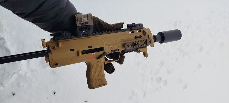
The first sighting of the MP7s in 2026 came in February, with several posts about the weapons on Telegram. On 6 February, a telegram channel affiliated from individuals from Ukraine SOF community posted a series of photographs of a brand new RAL 8000 MP7A2, with Ase Utra suppressor and Acro red dot on an Eratac USL mount. The caption praised the weapons “compactness, low weight, and practically no recoil” but noted that it has a short effective range, unique ergonomics and uncommon ammunition. The post went on to suggest that its best use would be as a PDW for snipers.
Another Telegram post, on 9 February, by Про Зброю, which has been described as a shooting instructor serving in the Ukrainian Army, described the MP7 as “extremely convenient, very compact and lightweight, a highly maneuverable weapon that allows for surprisingly controlled automatic fire against a “silhouette” target at distances of up to 100 meters and beyond. There’s practically no recoil or barrel flip when firing. A long burst can be completely placed in the target! The accuracy, thanks to the collimator sight, is excellent! And the sound of the shot is well muffled by the compact sound moderator.” The author’s primary complaint, however, was that 4.6x30mm ammunition is exotic and rarely available in Ukraine. It’s unclear how much ammunition has been supplied for the weapons. The earlier post included a photo of Fiocchi 4.6mm copper plated steel black tip ammunition.
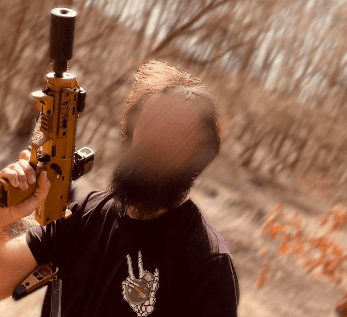
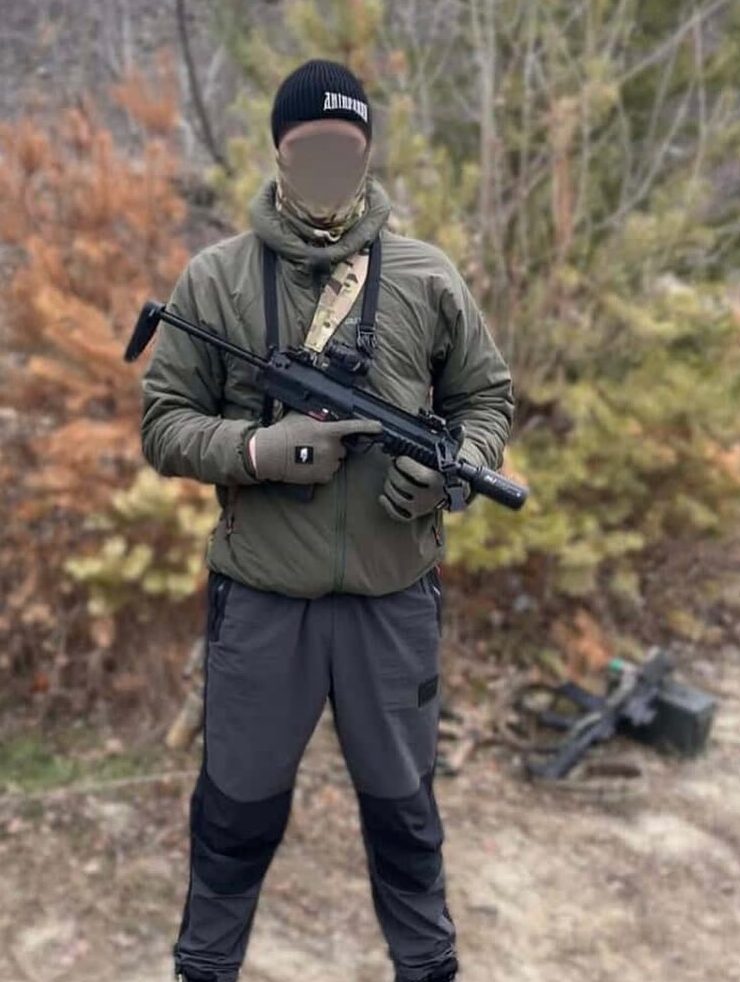
At the beginning of April a combatant with an HUR team shared a photo posing with an MP7A2 during a range trip. The individual shared some thoughts on the MP7 with me, he noted that it’s a “weapon more for bodyguards” and that while “the weapon is very cool” its best suited to specific roles. He noted that .300BLK is preferred for operational roles that require a quiet weapon. He also noted that the accuracy of the MP7 wasn’t as good as he’d expected. It’s unknown what sort of ammunition he used while testing the MP7. Again the weapon has the standard Ase Utra suppressor and an Aimpoint Acro red dot sight on an Eratac USL mount.
Most recently on 24 April 2026, ‘Explosive Department’ an instagram account affiliated with an element of the HUR’s Kraken Regiment shared a photograph of a RAL 8000 MP7A2 with an FDE Aimpoint Acro and an Ase Utra S Series suppressor.
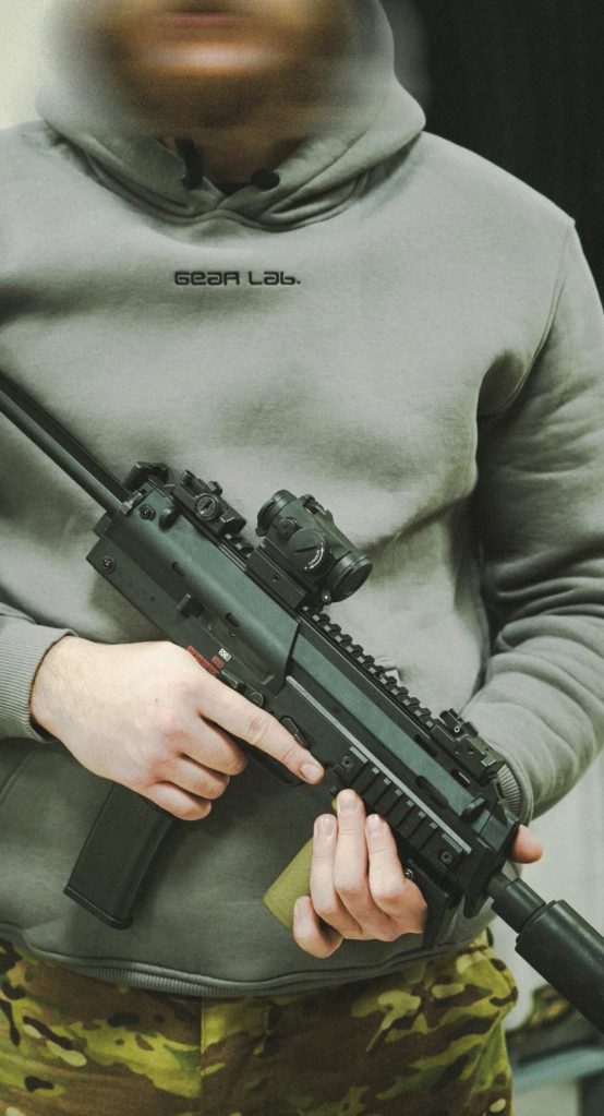
From discussions with sources its possible to confirm that these weapons, along with HK416A8s and MG4 and MG5s, have been provided to Ukraine by Heckler & Koch as part of German aid to Ukraine. They appear to have common accessory configurations including Ase Utra S Series suppressors and Acros on Eratac USL mounts. Imagery shows a mixture of 20- and 30- round magazines.
Thank you to colleagues at StreakingDelilah, MilitaryLand and to Mathias for their help with various elements of this article/video.
Support Us: If you enjoyed this video and article please consider supporting our work here. We have some great perks available for Patreon Supporters – including exclusive videos, custom stickers and early access to videos! Thank you for your support!