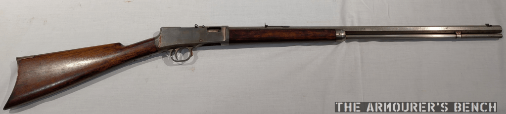
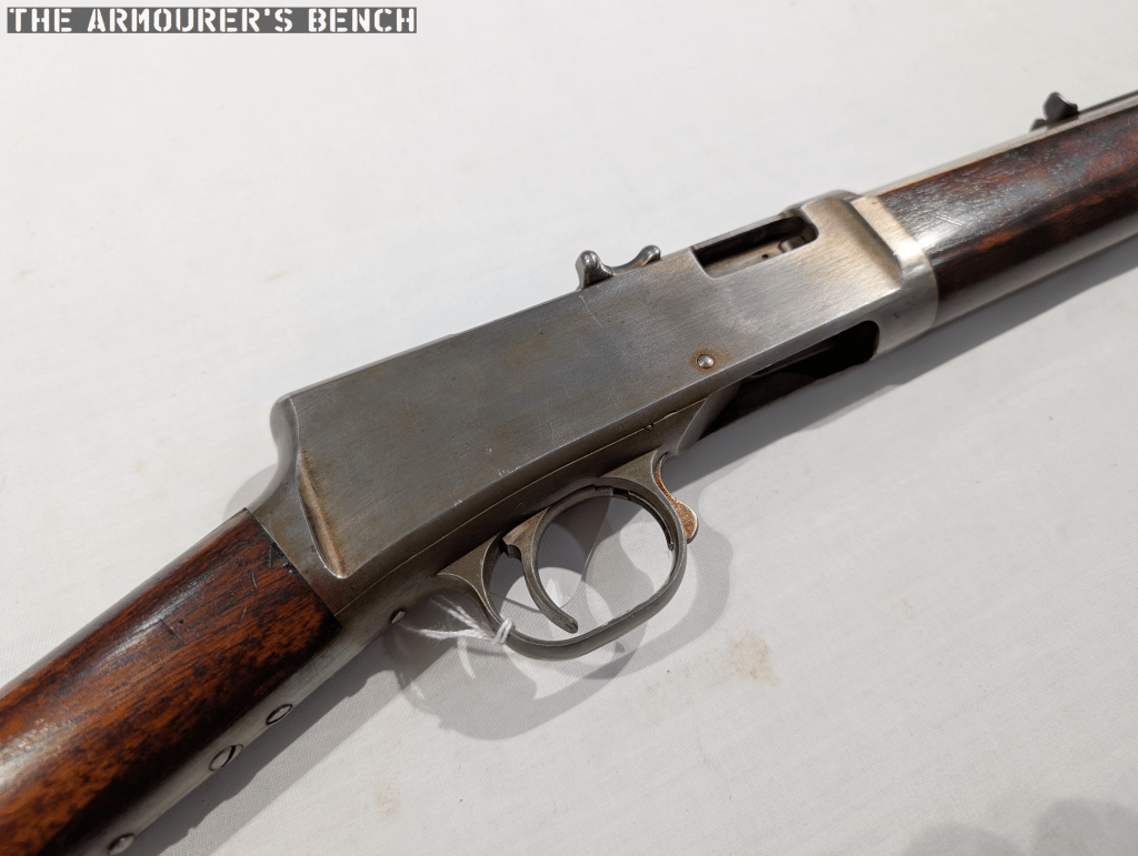
Earlier this year I had the pleasure of visiting my friends at the Cody Firearms Museum and while having a look through their collection we came across a really interesting rifle. The rifle isn’t currently on display and was safely tucked away in one of the museum’s vaults. When we began looking through the vault’s racks we came across what we initially thought were a number of John Browning prototypes from his work with the Winchester Repeating Arms Company. One of the prototypes immediately caught our eye as it had a T-shaped charging handle, something today which is synonymous with the AR-15/M16 platform.
In the past I’ve had the pleasure of examining over a dozen of John Browning’s prototypes (some videos are already published on the channel others will be published in the future – stay tuned), this rifle, however, isn’t a Browning. It’s a Mason.
William Mason is probably best known as the man behind the Colt Single Action Army, the Model 1877 and what would become the Model 1889. In 1882, Mason left Colt and joined Winchester. While originally he has been recruited to work on revolvers for Winchester, a topic for another day, he became Winchester’s Master Mechanic and was responsible for bringing many of John Browning’s designs to production. Following the Brownings’ schism with Winchester in 1903, the company continued to develop their own designs and a number of these came from Mason.
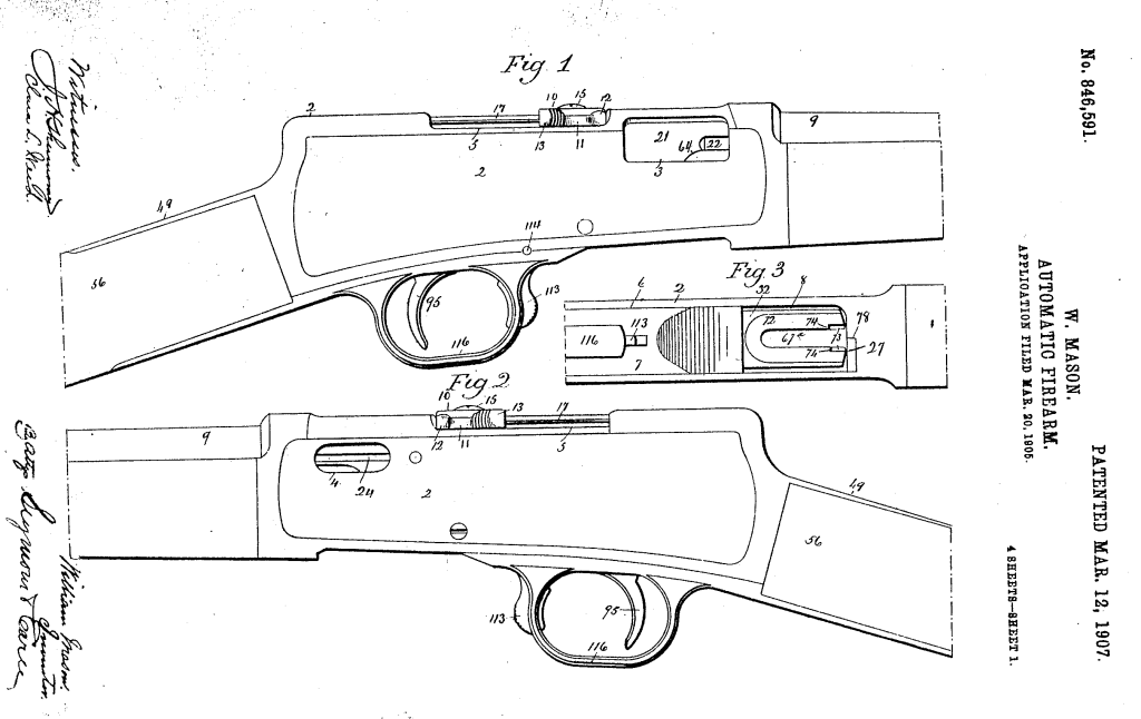
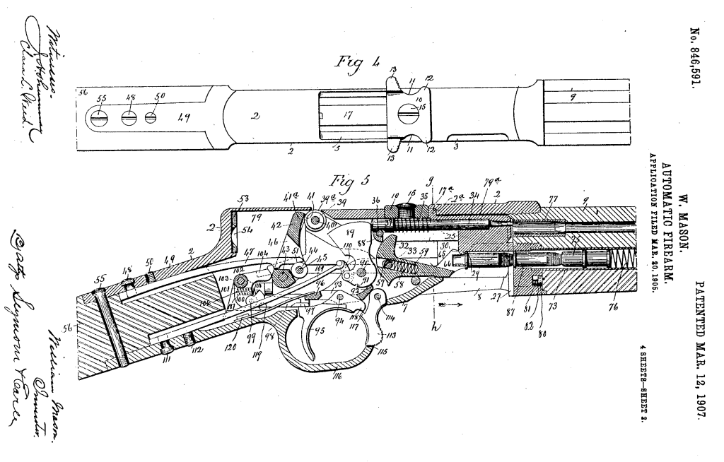
This rifle’s patent was filed in March 1905, and granted on 12 March, 1907 as No.846,591. It is a .22 calibre, semi-automatic rifle which feeds from a conventional tube magazine but has a number of interesting features.
The Action
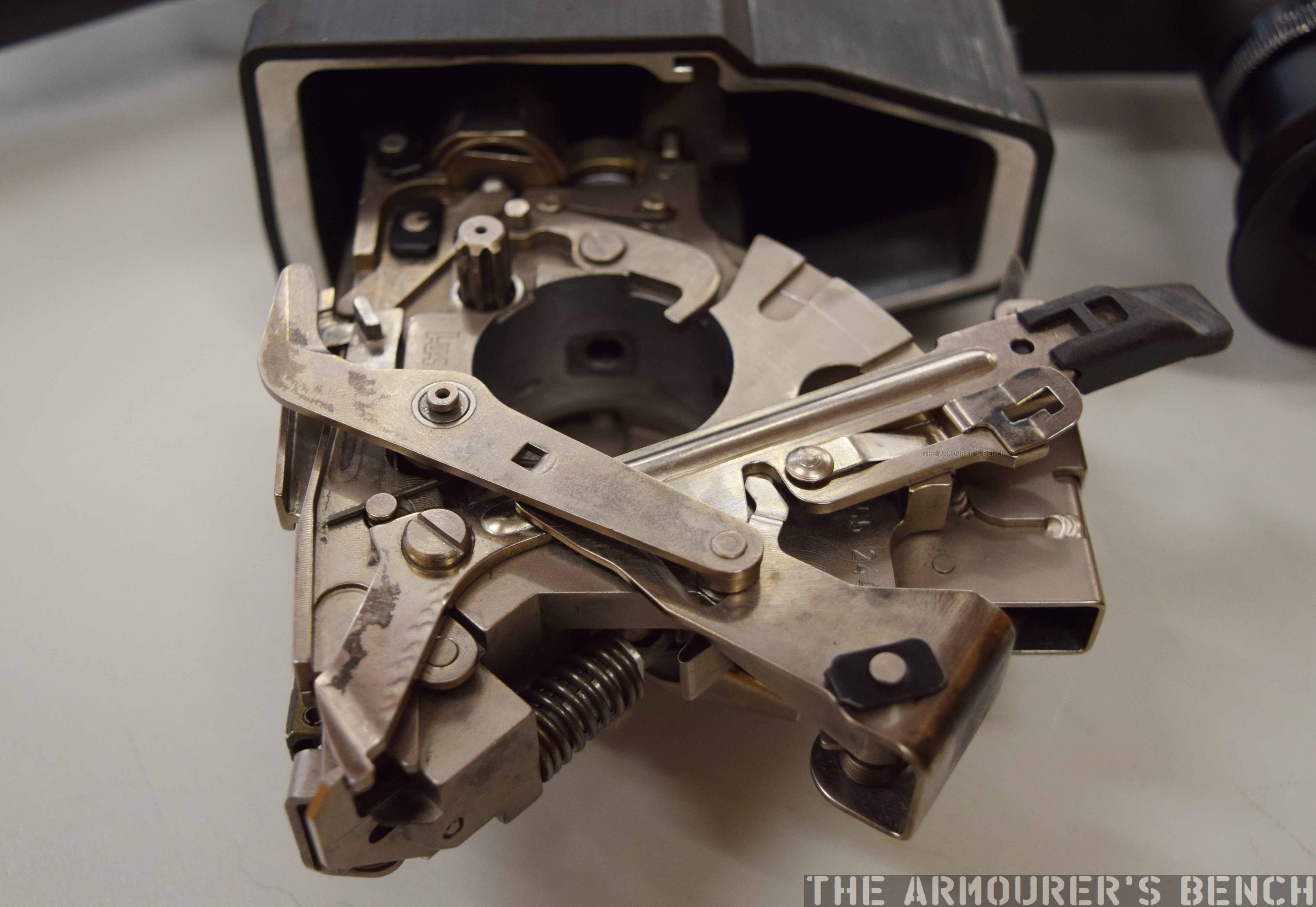
Mason, in his patent for the rifle, describes the weapon’s action as a ‘automatic balanced breech-block gun’, by which he means what we now know as a blowback. He describes this as: “a breech-block which is not positively locked in its closed and recoil-taking position but weighted with reference to the energy developed by the explosion of the cartridge to be used in the gun, so that its inertia takes the initial shock of recoil.”
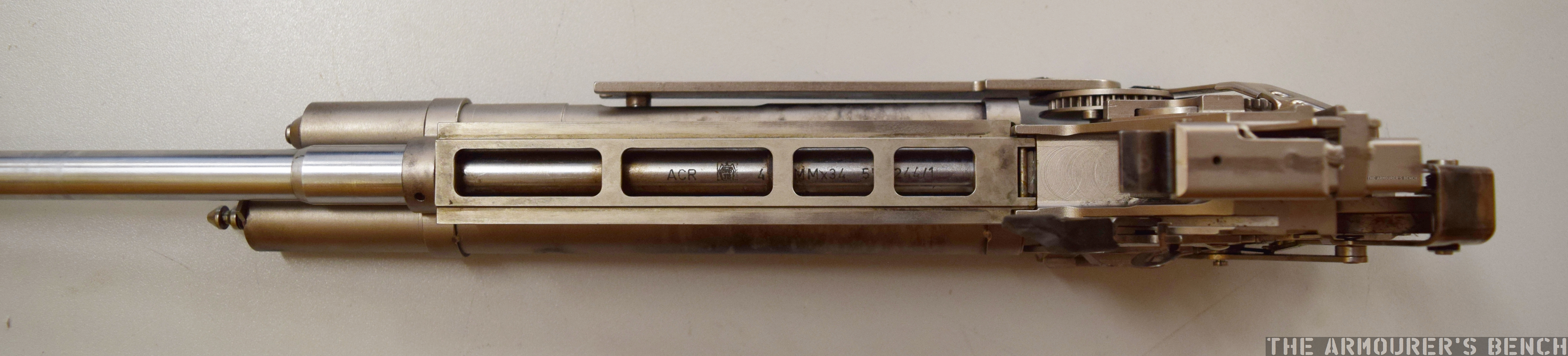
The only marking visible on the firearm is on the top of the receiver, a number marking: ‘7295’.
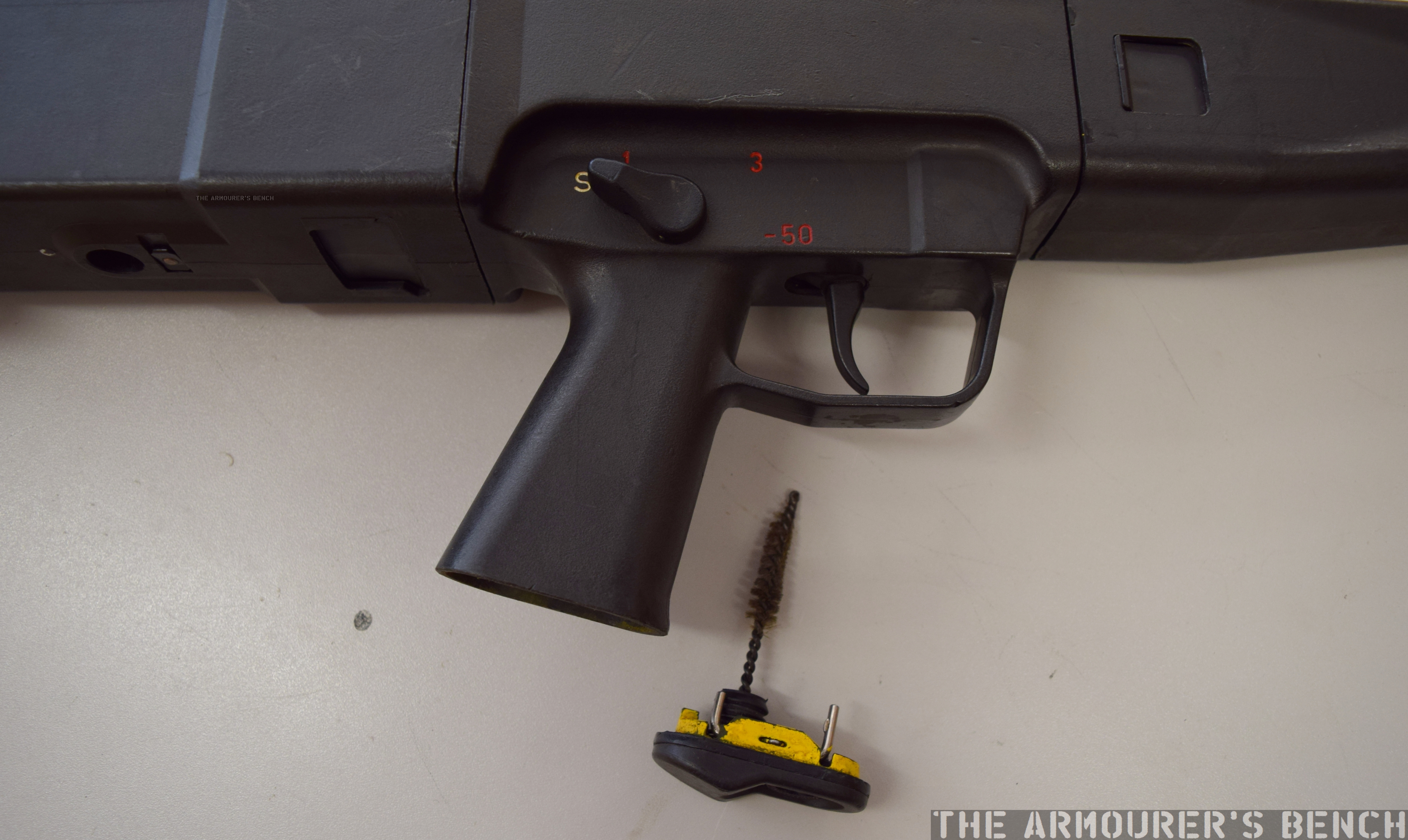
Safety
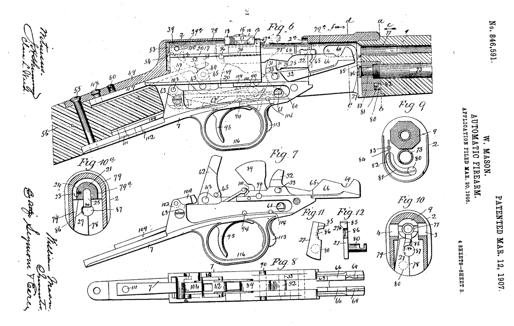
The rifle also has a trigger locking safety located at the front of the trigger guard. The patent describes this:
“provide the gun with a ‘safety’ in the form of a lever, suspended by its upper end from a pivot in the lower tang and having its lower end entered into a slot in the forward reach of the trigger-guard, which is a part of the said lower tang. The said lever is formed with a stop-shoulder, co-acting with a stop-finger at the forward end of the trigger. When the safety is pushed rearwardly, its shoulder is moved under the finger, whereby the trigger is locked against operation under any circumstances.”
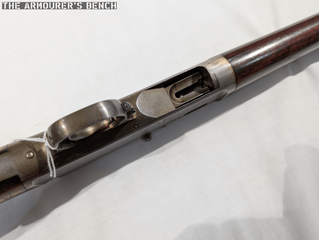
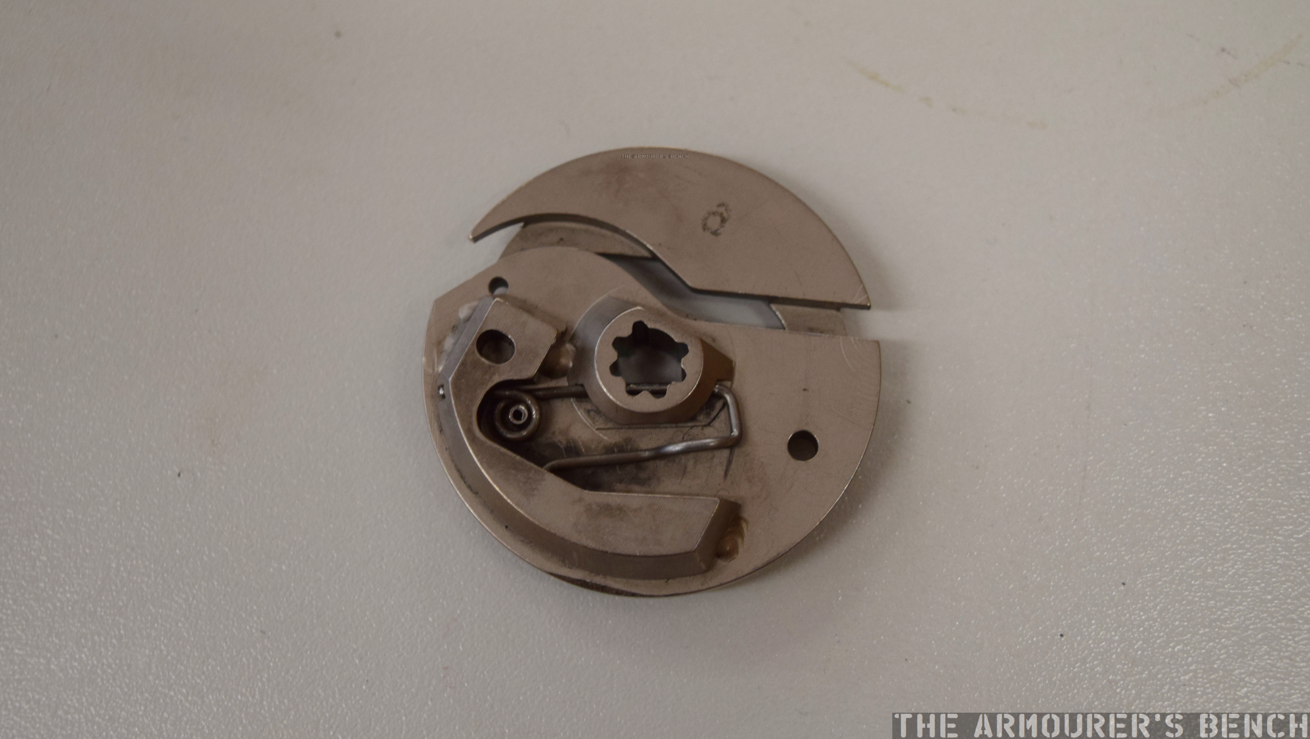
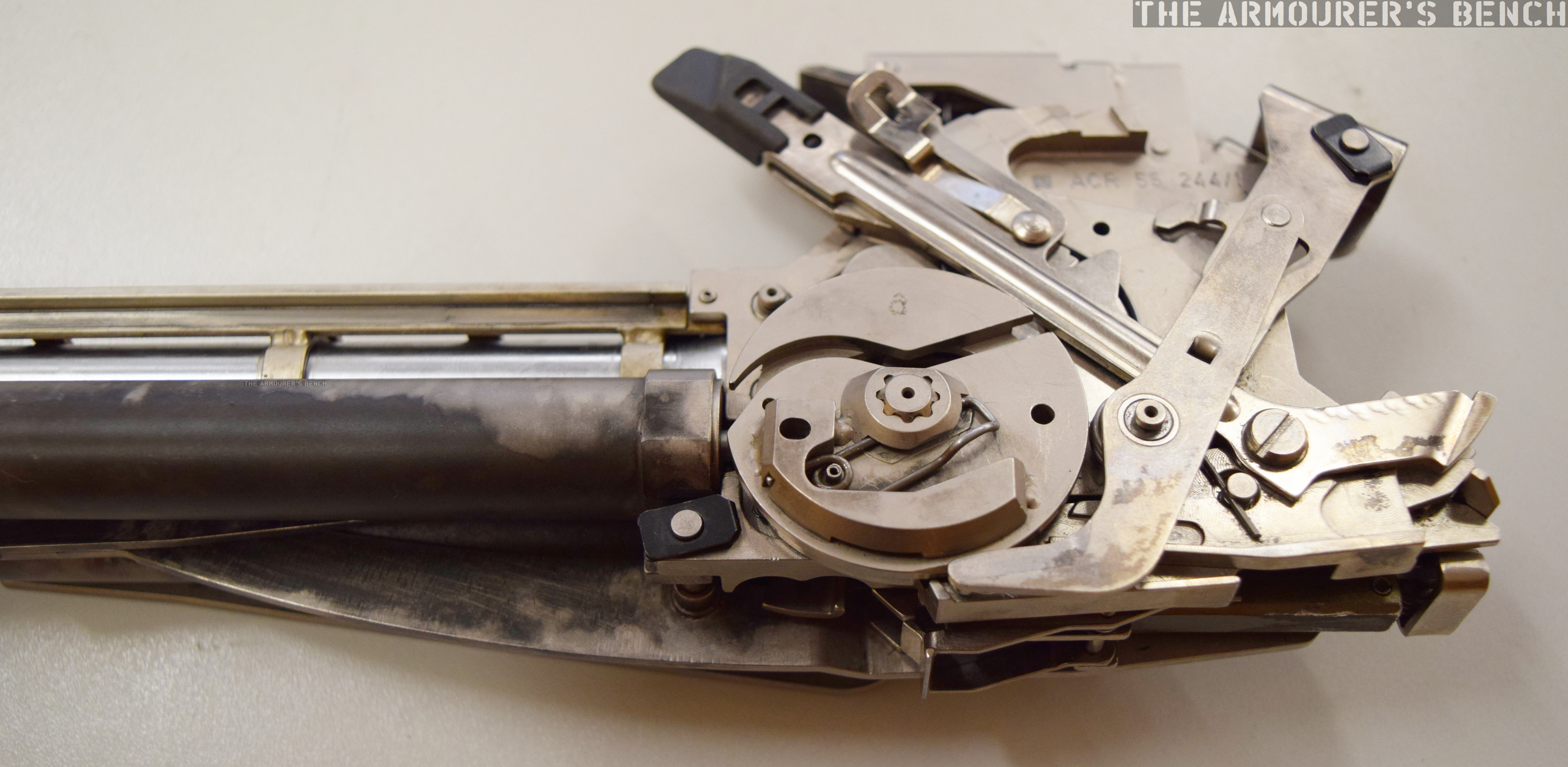
Loading
The rifle has a swinging carrier which when the breech block cycles it acts on what Mason calls the ‘carrier arm’ via a cam which moves the arm up and down allowing a round to move into the action from the tube magazine when the bolt had moved sufficiently to the rear. The rifle’s tube magazine is loaded by pushing the carrier up and thumbing cartridges into the magazine.
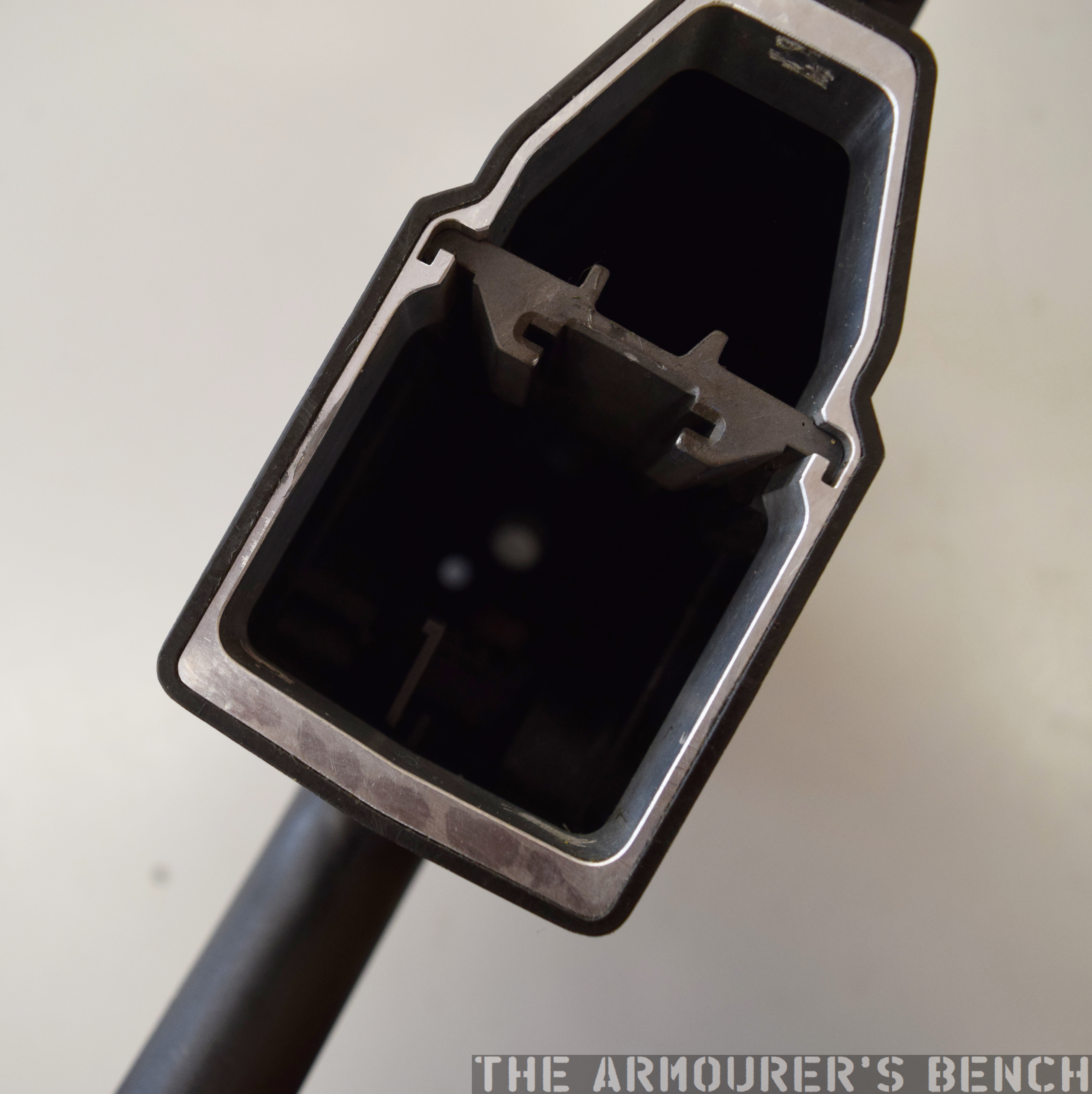
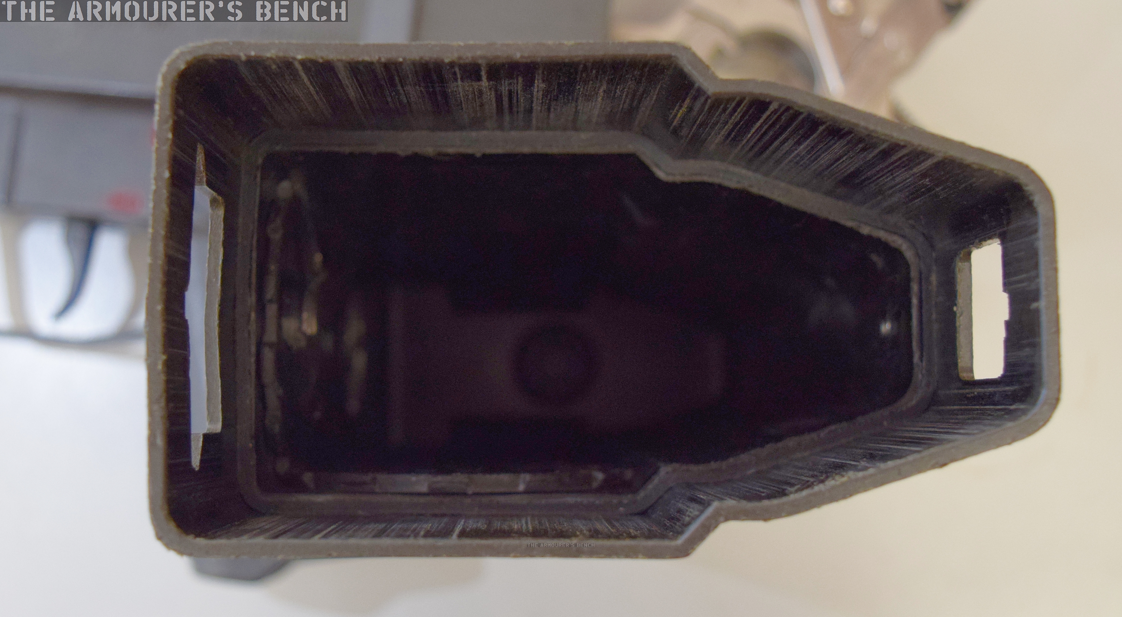
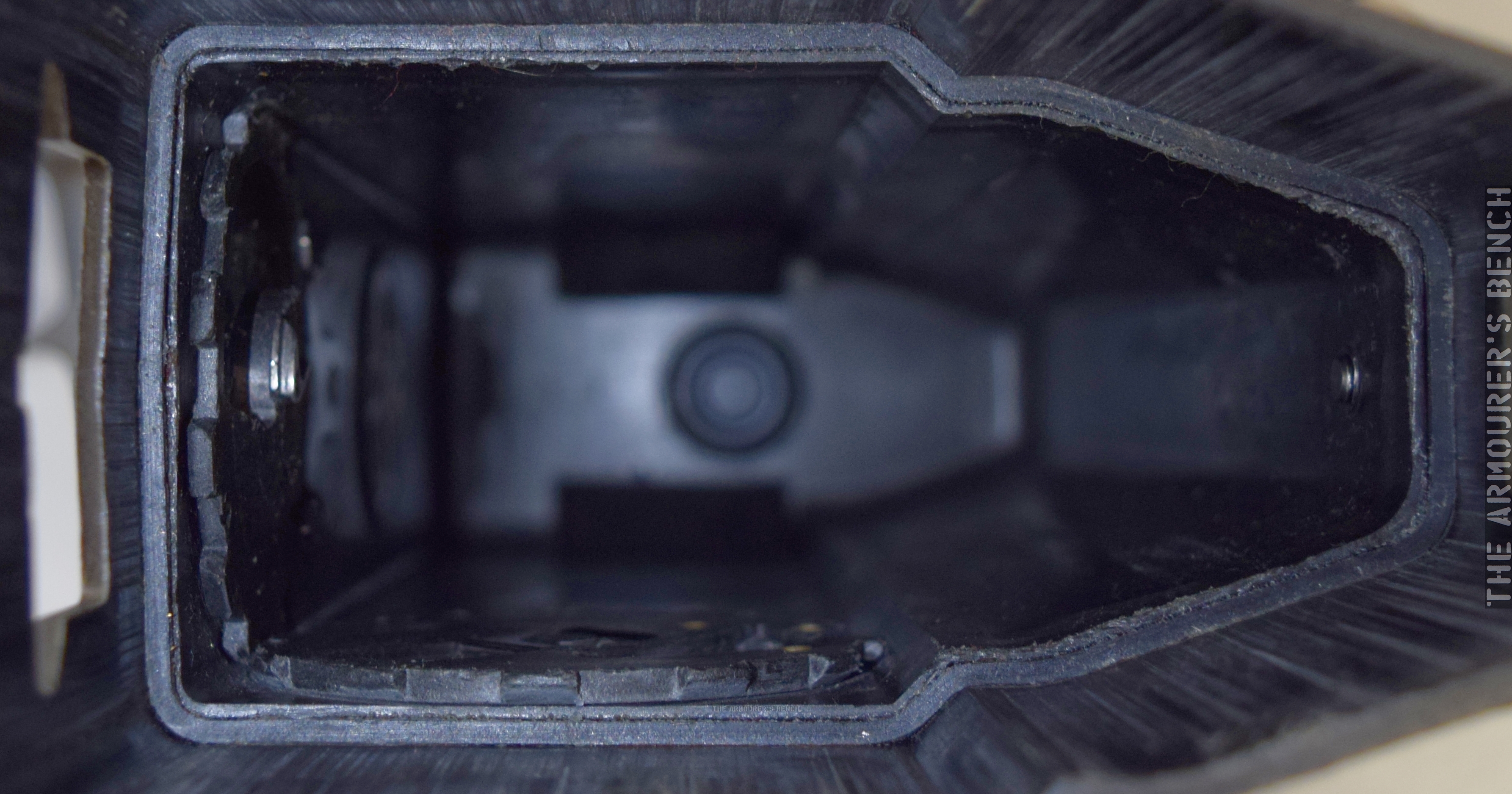
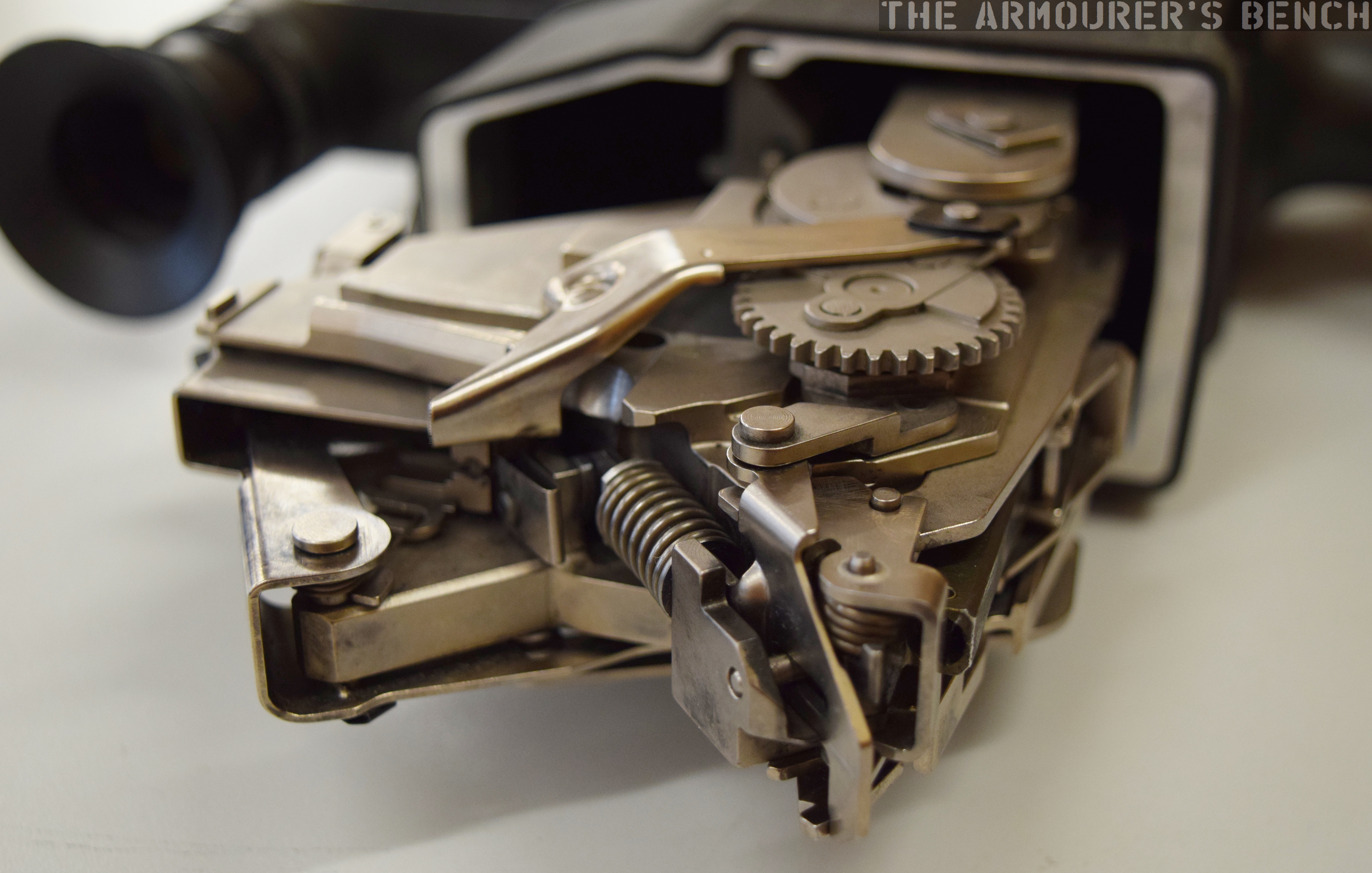
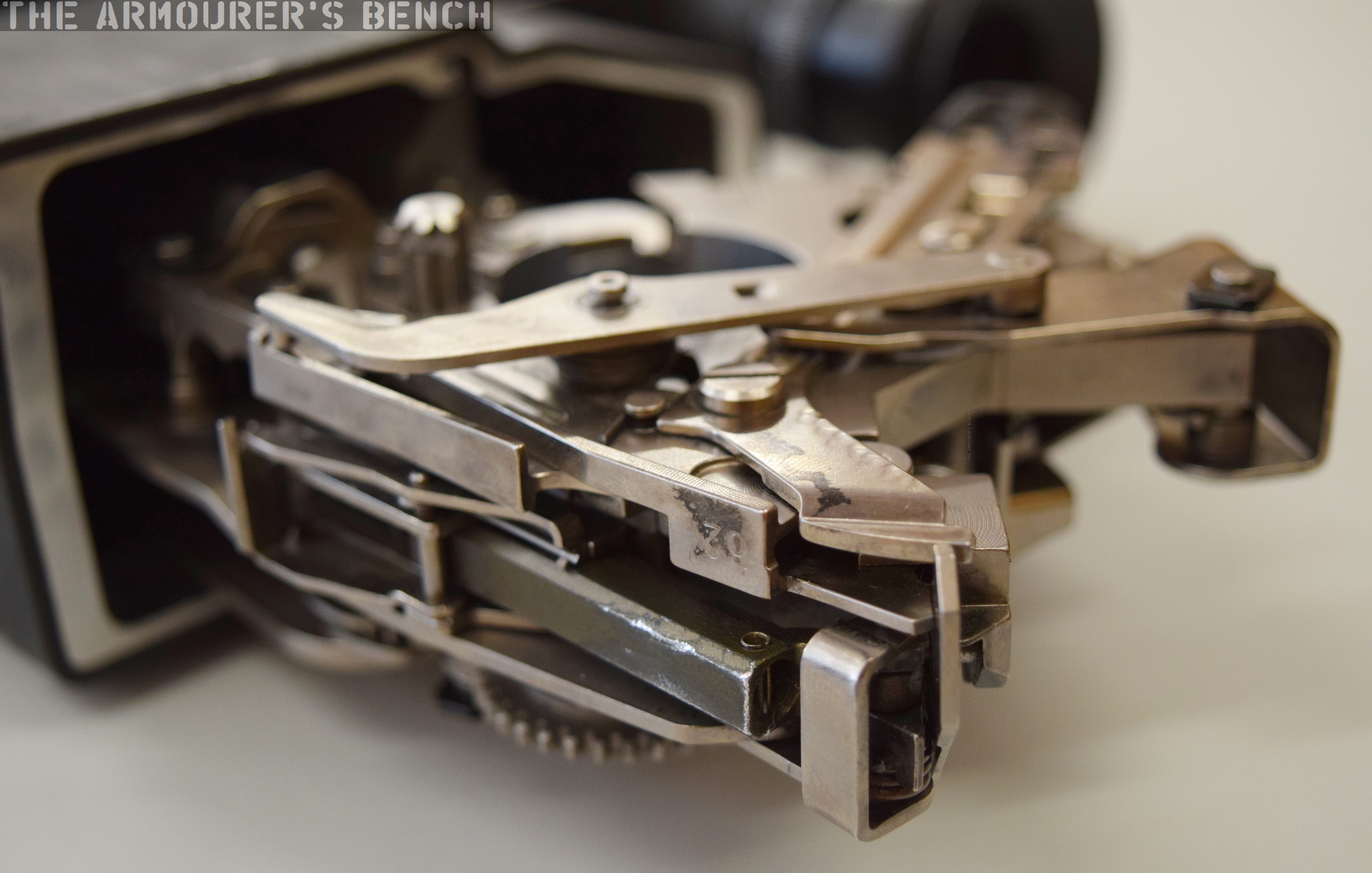
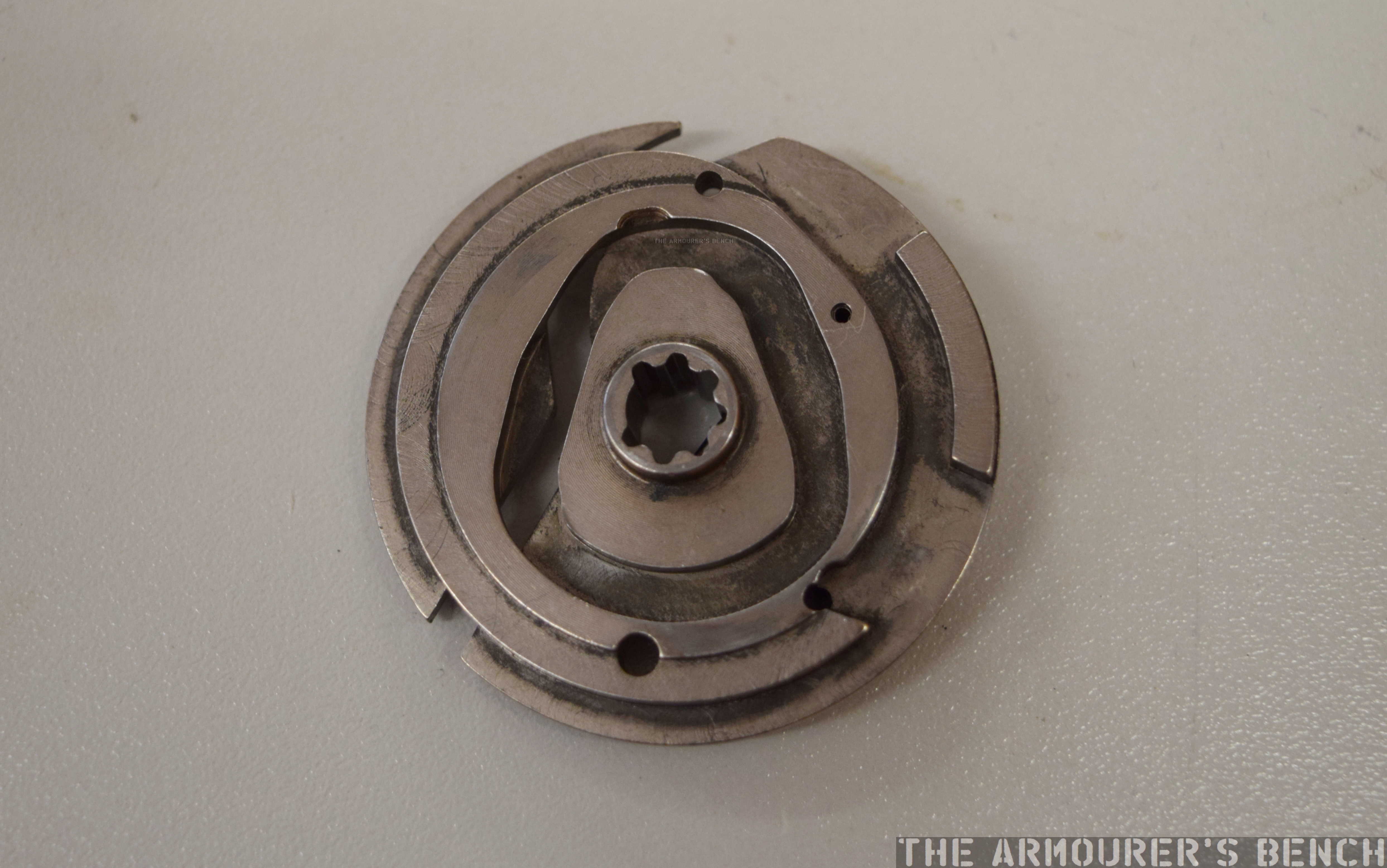
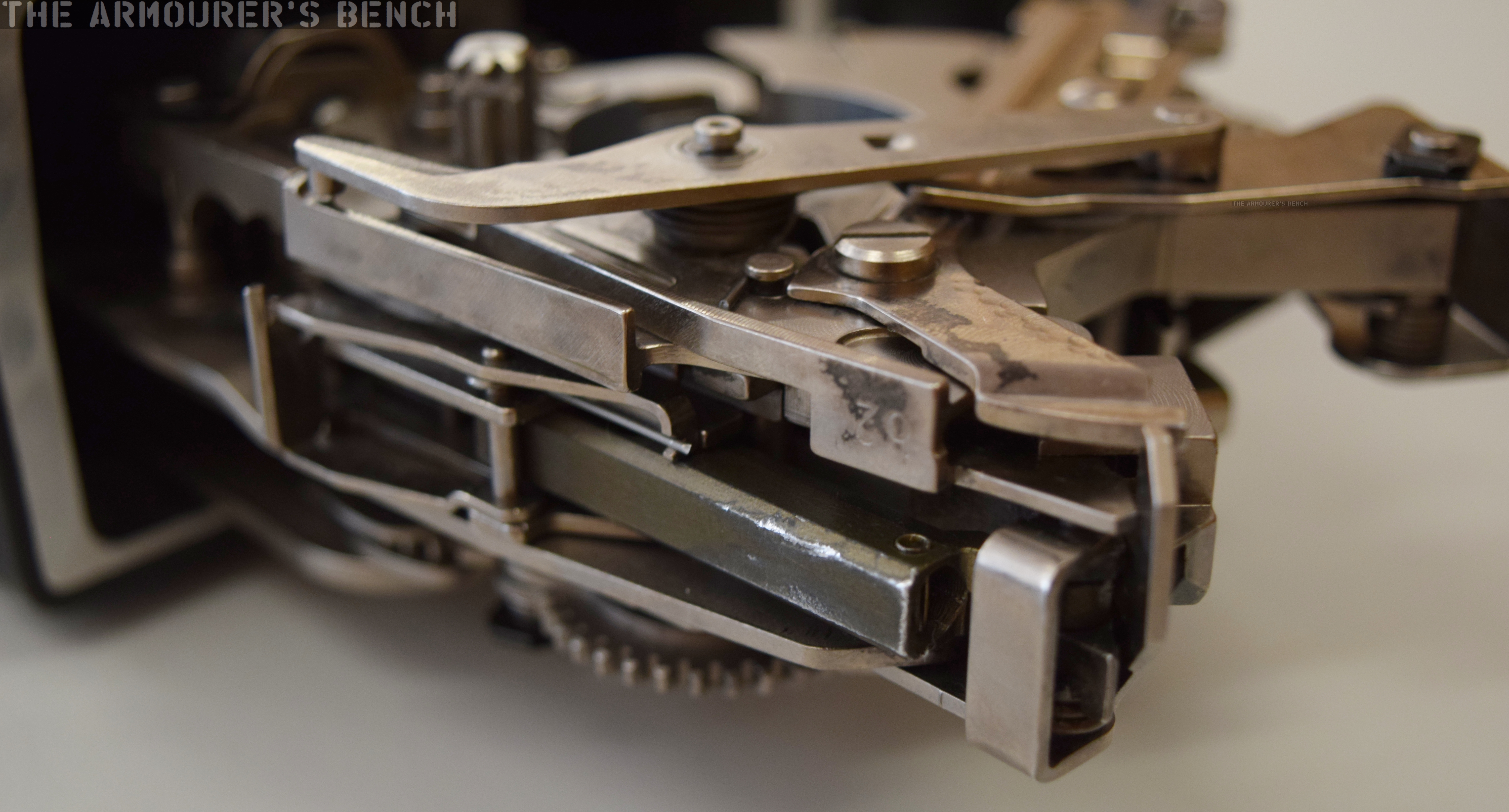
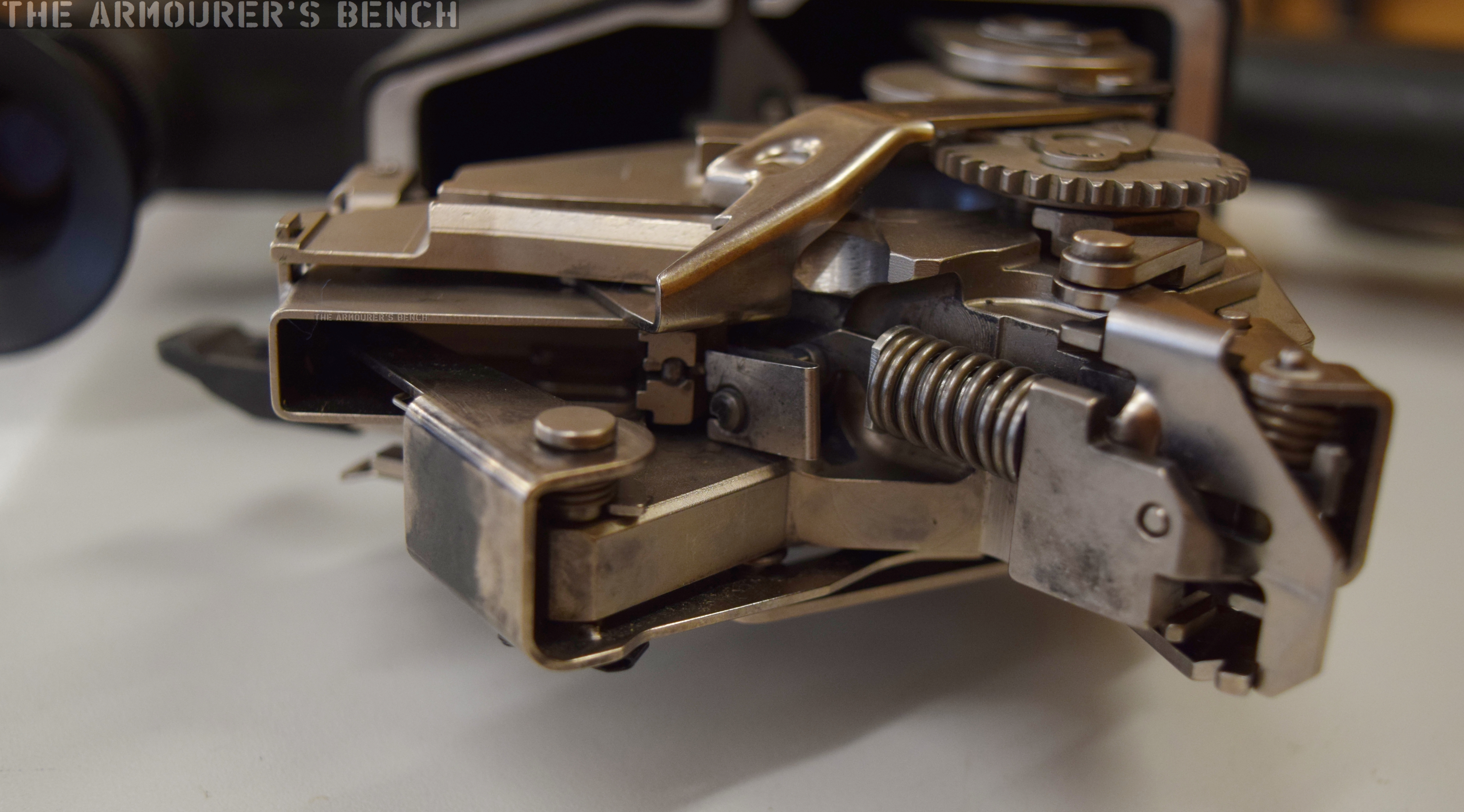
Anti-friction Rollers
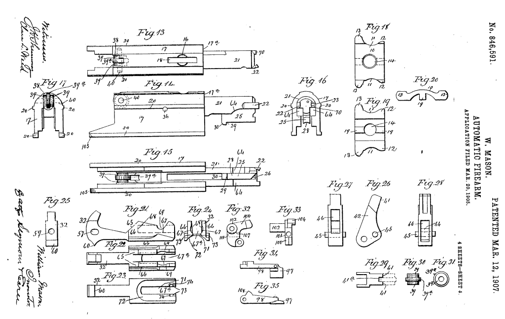
Another intriguing feature of the rifle’s action is the set of rollers located in the top of the breech block which prevent friction from the block against the receiver. The rollers also act on a lever which is under spring tension which returns the breech block forward – Mason used this in the place of a more conventional return spring assembly. Instead the lever is acted on by a flat spring which Mason felt allowed him to “secure a marked economy of space” in the receiver, not requiring a coil spring and the space needed to compress it. Additionally, at the rear of the receiver there is also a buffer made from ‘vulcanised fiber’, vulcanisation is a process which strengthens and improves the durability of a material. As we didn’t fully disassemble the rifle we can’t confirm the buffers presence in the prototype.
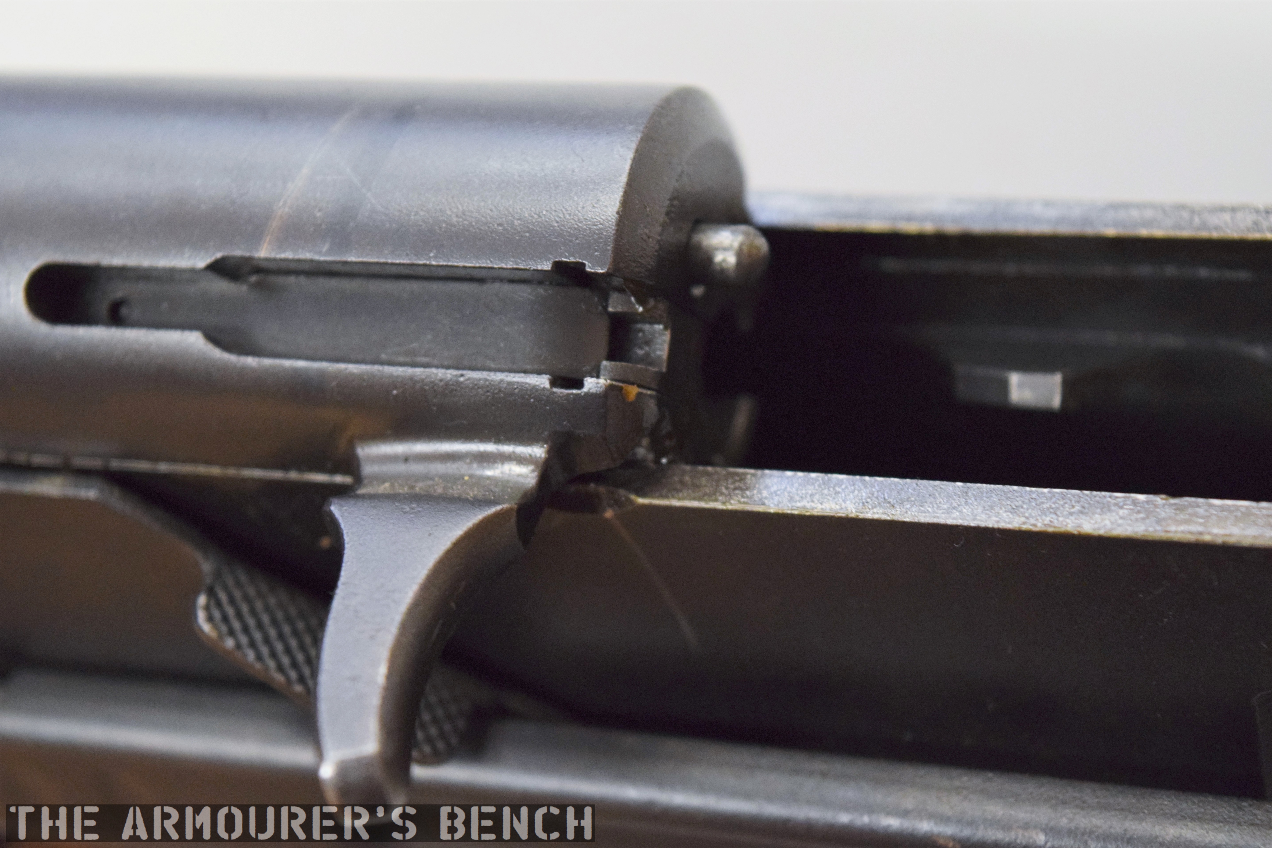
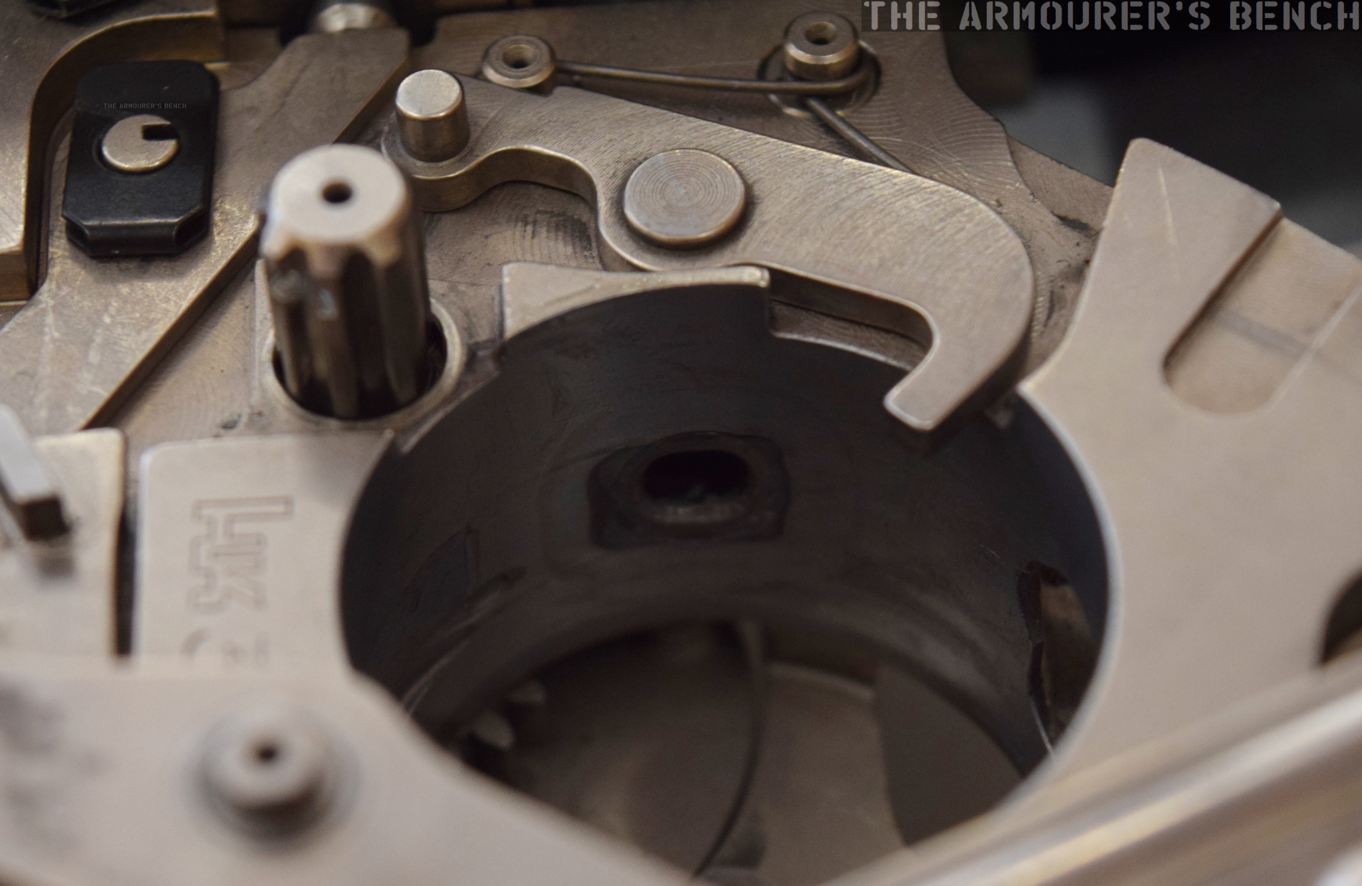
Mystery Hole
On examining the rifle I was a bit perplexed by what the purpose for a smaller hole opposite the ejection port was. It is too small to be an ejection port and on the same side as the ejector{?} On reading Mason’s patent it became clear that this was an emergency gas port to allow gas to escape the receiver in the event of a major failure. Mason explains this:
“gas-escape opening is so constructed and arranged with reference to the construction and arrangement of the breech-block that it permits the escape of gas through it when the breech-block is in its closed position, so that in case there should be a leakage of gas due, for instance, to the splitting of the head of a cartridge the gas will work back and escape through the said opening without damage to the gun, whereas in the absence of such a gas-escape opening, the breech-block might be broken or deformed by the force of the gas bending it from left to right toward the ejection-opening.”
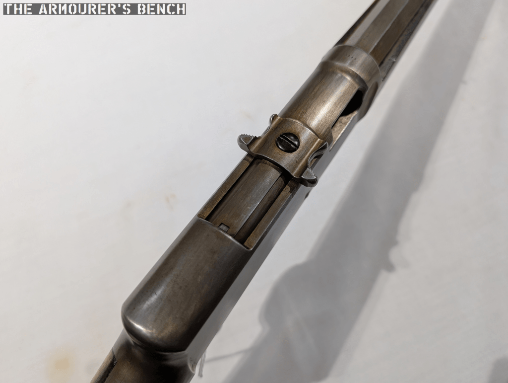
Charging Handle
Perhaps the most intriguing external feature is the charging handle. Is it the first rifle with a T-shaped charging handle? Here’s how Mason’s patent describes it:
“breech-block handle arranged transversely with respect to the top of the gun-frame and in length exceeding the width thereof. The ends of this handle are formed with finger-cuts, flanked at their forward ends by ears and at their rear ends by knurled, or roughened fingers, extending outwardly beyond the planes of the side walls of the frame, so as to be readily engaged by the finger and thumb, respectively. The said handle is also formed with a centrally-arranged screw-hole, receiving a screw, entering a screw-hole in the forward end of a longitudinally-reciprocating non-rotatable balanced breech-block.”
All-in-all it’s a really interesting patent and well worth a read to understand some of the nuances I don’t have time to cover here.
Despite the prototype’s interesting design it never made it into production. In 1903, Winchester had introduced the Model 1903, a tube magazine-fed, blowback rifle, chambered in .22 Winchester Automatic. The Model 1903 was designed by another of Winchester’s engineers, T.C. Johnson, and instead of a T-shaped charger used a plunger, which I think is a little less elegant but the Model 1903 was a success, remaining in production for decades, so it seems that Mason’s design wasn’t needed. As a result it would be another 60 years before a rifle using a T-shaped charging handle became popular in the US. Mason continued to work for Winchester until his death in July 1913, aged 76.
Massive thanks to my good friends at the Cody Firearms Museum for allowing me to examine this rifle and thank you to my friend Tyler Berger for his help filming this video. Please do check out the museum online at centerofthewest.org/our-museums/firearms/ and if you can head out there this summer to visit one of the best publicly displayed collections of firearms in the world.
Support Us: If you enjoyed this video and article please consider supporting our work here. We have some great perks available for Patreon Supporters – including early access to custom stickers and early access to videos! You can also find us on the History of Weapons & War app. Thank you for your support!


