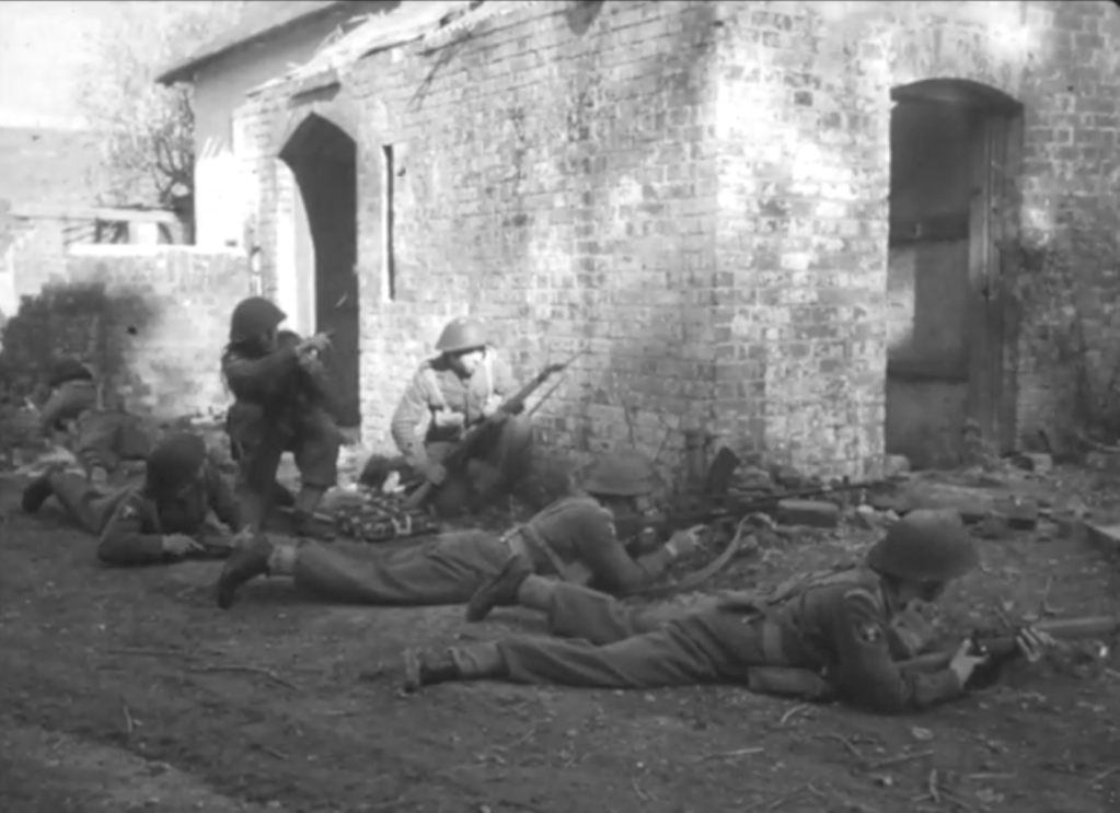
Recently, while looking though British Army Cold War training films, I stumbled upon something I never expected to see: a clip of an MCEM-2 firing! I was searching through British Cold War training films and watching a 1953 film titled ‘Village Clearing’ at first it seemed pretty standard fair albeit showing an impressive set-piece of tanks attacking a village. And then about 8 minutes in I spotted something unusual, the prototype MCEM-2, in the hands of one of the village’s defenders.
The 1953 training film shows a company size attack by the Royal Welch Fusiliers on an enemy strongpoint but then shows a section/squad assault on a building. The opposing force or OPFORCE are wearing airborne HSAT helmets and are armed with American weapons including M1 Garands, some first pattern M1918 BARs and a lone MCEM-2! This was likely done to differentiate the British troops from the OPFORCE – either they wanted a generic look or didn’t have any soviet weapons or kit available as is seen in later training films. My guess would be that the prototype may have come from the British Army’s Small Arms School Corps Collection which has historically maintained a working collection of foreign, historic and prototype weapons for familiarisation and training purposes.
The MCEM-2 or Machine Carbine, Experimental Model No.2 was developed by a Polish engineer, Jerzy Podsedkowski. Work on the design began in 1944 but it was not seriously tested until after the end of the war. We can see from this brief clip that Podsedkowski’s design was small, compact and innovative. It fed from an 18 round magazine which like the later Uzi, Sa.23 and RAK Pm.63 was inserted into the pistol grip. While this kept the weapon compact and theoretically holster-able the MCEM-2’s high rate of fire, around 1,000 rounds per minute, meant that it was expended extremely rapidly.
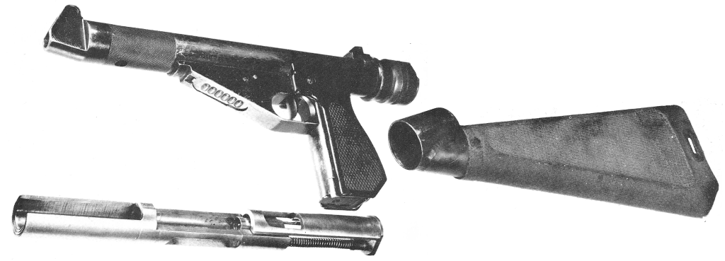
The MCEM-2 disassembled (via Firearms.96.lt)
The MCEM-2 (Machine Carbine Experimental Model No.2) was a small, compact, innovative design. The weapon had a holster stock and a wrap-around breech block which was inclosed in a tube metal receiver. We can see the bolt in this photograph. In 1946 Podsedkowski, assisted by another Polish engineer, Aleksander Ichnatowicz, improved the MCEM-2, seeking to slow its rate of fire with a heavier bolt. The MCEM-2 was tested at the Royal Navy’s Gunnery School at HMS Excellent in August 1946. Excellent’s Commandant Michael Le Fanu, later an admiral and First Sea Lord, noted in his report that it was a “well engineered weapon, handy to carry about and suitable for use by seamen” but did note that “the high rate of fire makes the weapon uncontrollable in automatic and dangerous in the hand of semi-skilled users.”
Despite improvements the new MCEM-6 was eventually rejected with a Harold Turpin design favoured before it too was rejected. Hopefully, we’ll be able to take a look at some of these designs upclose in future articles/videos.
If you enjoyed this video and article please consider supporting our work here. We have some great perks available for Patreon Supporters – including custom stickers and early access to videos! Thank you for your support!
From the late 1960s into the 1990s, Northern Ireland suffered a long period of sectarian violence, commonly known as The Troubles. Without going into too much detail about the conflict, other sources do a much better job than I can today, the violence saw Irish Republican paramilitary groups, Ulster Loyalist paramilitary groups and British security forces involved in a protracted low-level conflict with a Republican insurgency fighting not just British forces but Loyalist paramilitaries like the Ulster Volunteer Force (UVF), the Ulster Protestant Volunteers (UPV) and the Ulster Defence Association (UDA). This article/video has no intention to comment on the conflict itself, merely examine a weapon produced during the period.
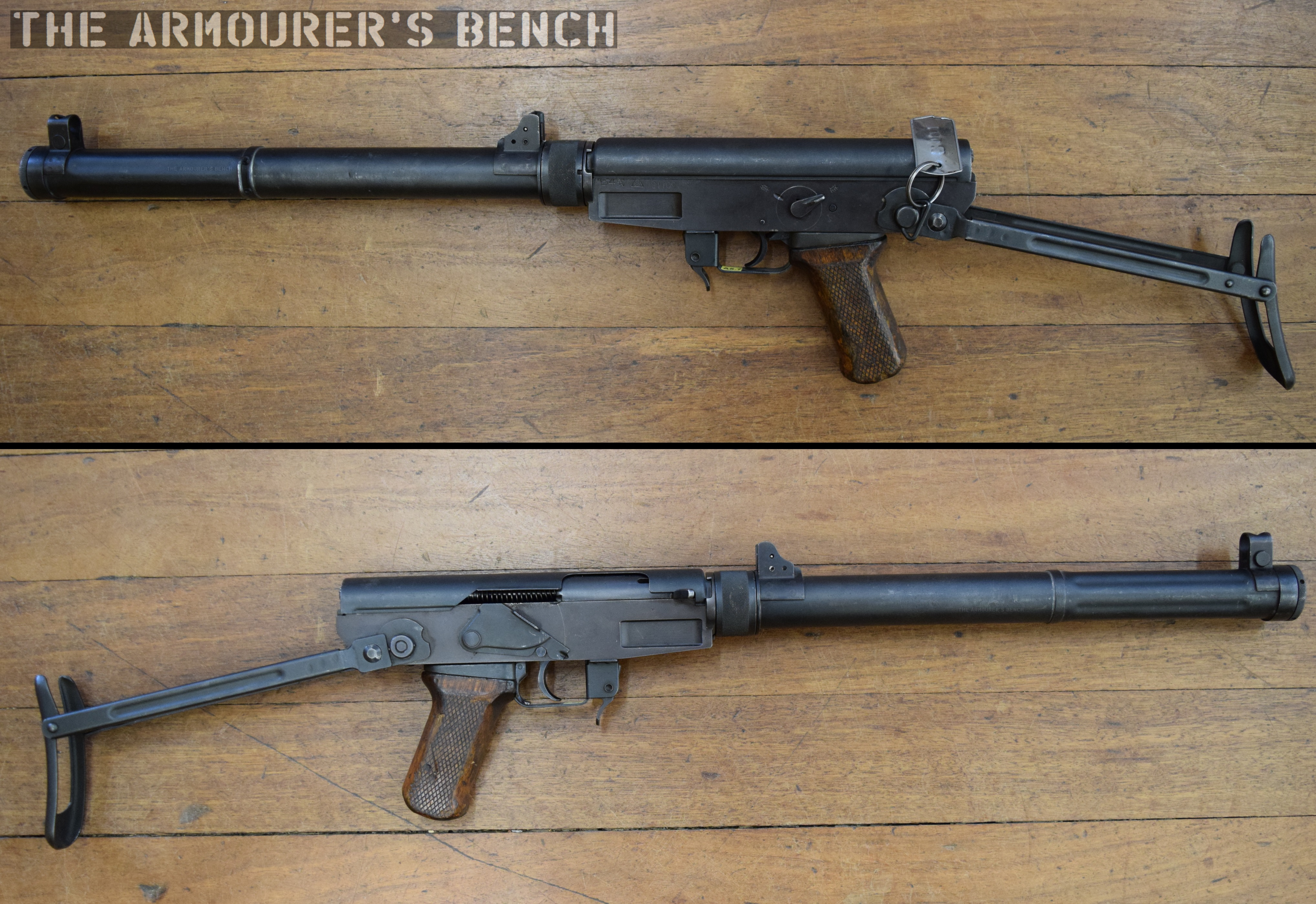
This copy or clone of a Sterling Mk4 / L2A3 submachine gun is believed to have been assembled by Loyalist paramilitaries although which group and its origins are unclear. Loyalist groups during the 60s and 70s tended to be less well armed and relied more heavily on improvised small arms and weapons stolen from military and police armouries and personnel than Republican groups. When tensions rose in the late 1960s, the Loyalists were largely equipped with obsolete and outdated weapons.
Right side view of the Sterling clone (Matthew Moss)
Sammy Duddy, a member of an early Loyalist group, the Westland Defence Association, and later a press officer for the Ulster Defence Association, recalled the dire state of their arsenal at that time:
“[…] we had no guns. The IRA had automatics [machine-guns], high-velocity sniper rifles, powerful pistols, the lot, but we had fuck all. There were virtually no guns on the Loyalist side. The only weapons we had were baseball bats and I just thought to myself, ‘what the fuck are we going to do when they [the IRA] come in with their machine-guns? Throw bats at them?’”
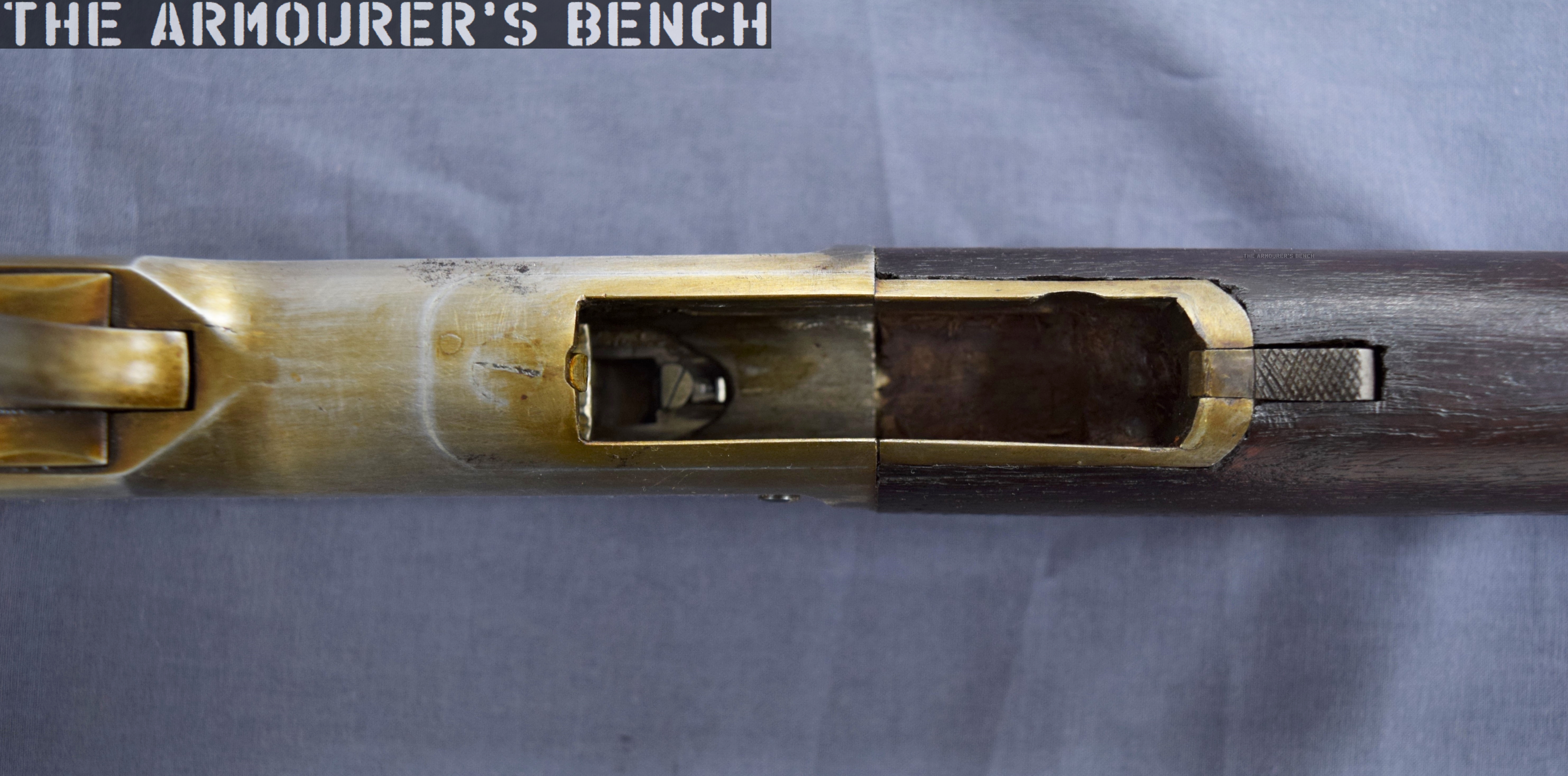
The Ulster Volunteer Force (or UVF) took to stealing what weapons and spare parts they could from the British military and Royal Ulster Constabulary. Weapons assembled from damaged captured Sterlings and Sterling spare parts kits became common. In this case, this weapon has a number of cannibalised original Sterling parts which have been paired with a craft-made receiver tube. From examination we can see that the weapon’s end cap has a Sterling part number stamp ‘CR110’ inside. Similarly the weapon has a factory-made plastic grip. Other factory made parts include the helically grooved bolt, the two recoil springs and the charging handle. There is also seemingly a factory-made trigger group and magazine release button. The magazine is well sized and utilises various parts from a Sterling’s magazine release including the button, an set screw and catch piece.
The weapon uses a Sterling’s factory-made pistol grip and trigger mechanism – a remarkably sophisticated craft-made weapon (Matthew Moss)
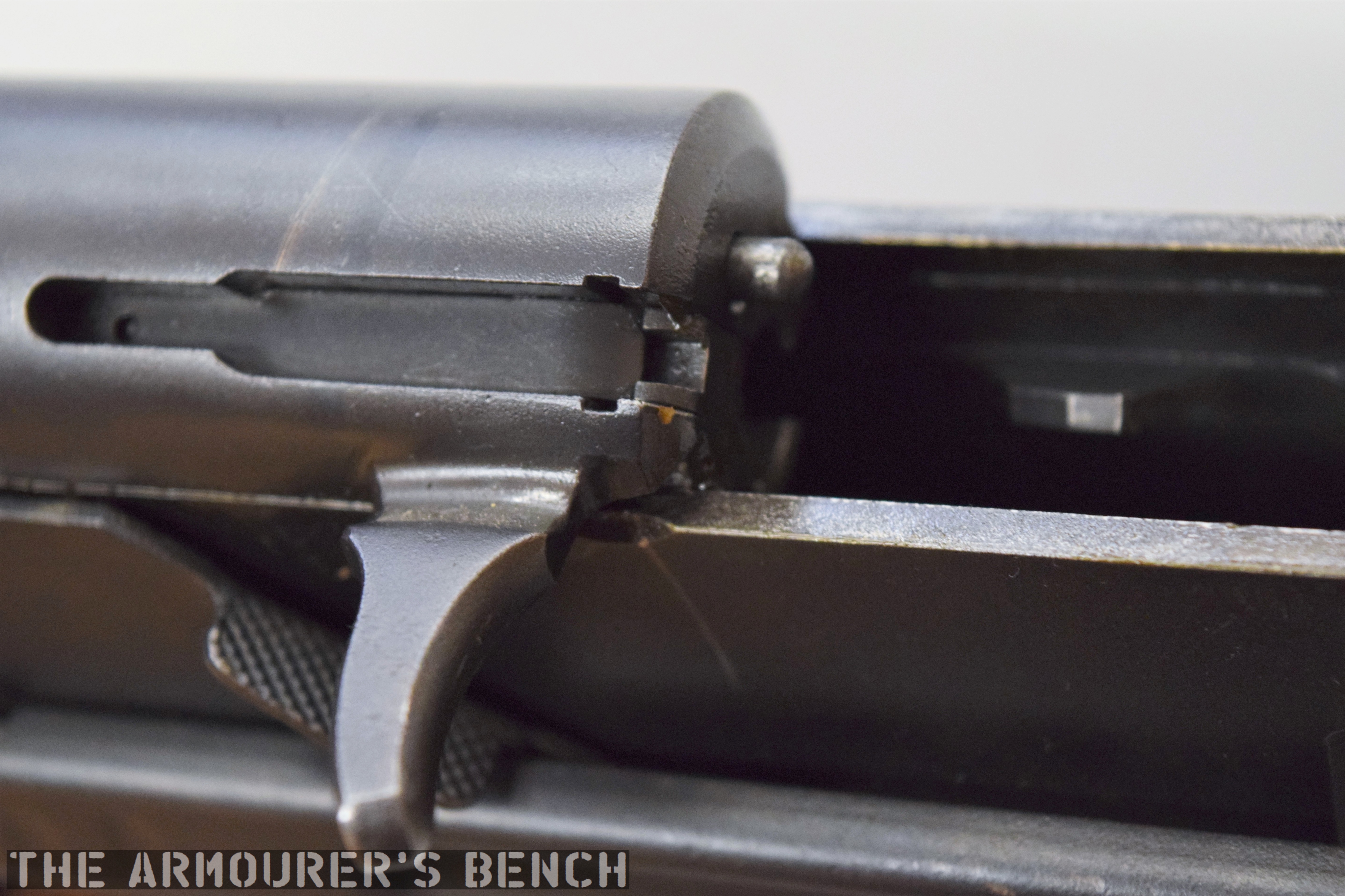
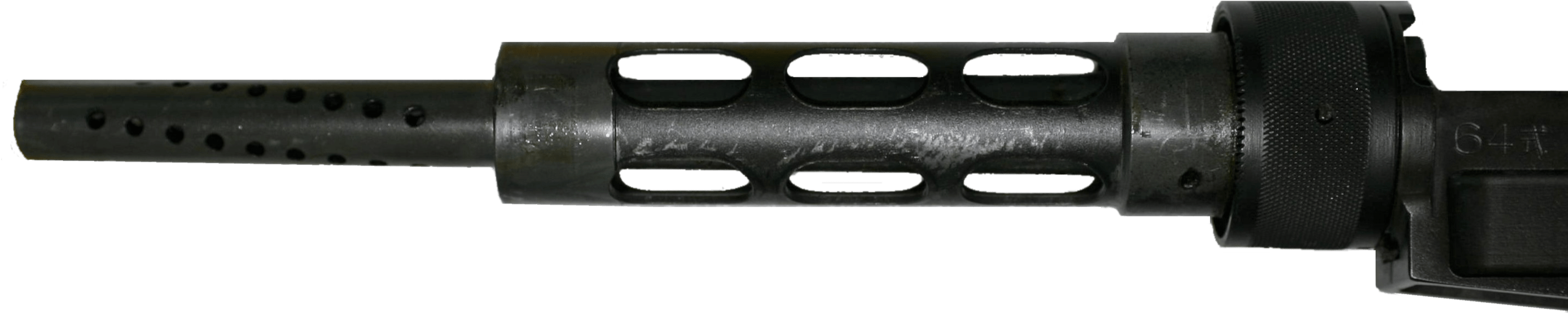
The trigger assembly housing is welded and ground smooth where it joins with the tube receiver. On factory-made guns there is a visible seam. The poorer quality tube steel of the receiver also appears to have drooped or bent a little around the middle of the weapon. The holes in the barrel shroud are of uniform size but they are roughly drilled and not equally spaced. At the front of the receiver we can see they have retained the barrel with a pair of large bolts, suggesting that the barrel may have been factory made too. There is now end cap catch at the rear nor provision for a folding stock either. While whoever made the receiver tube went to the trouble of added hand stops found on the actual Sterling they are clearly only lightly welded on.
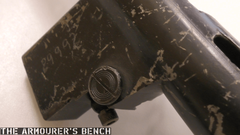
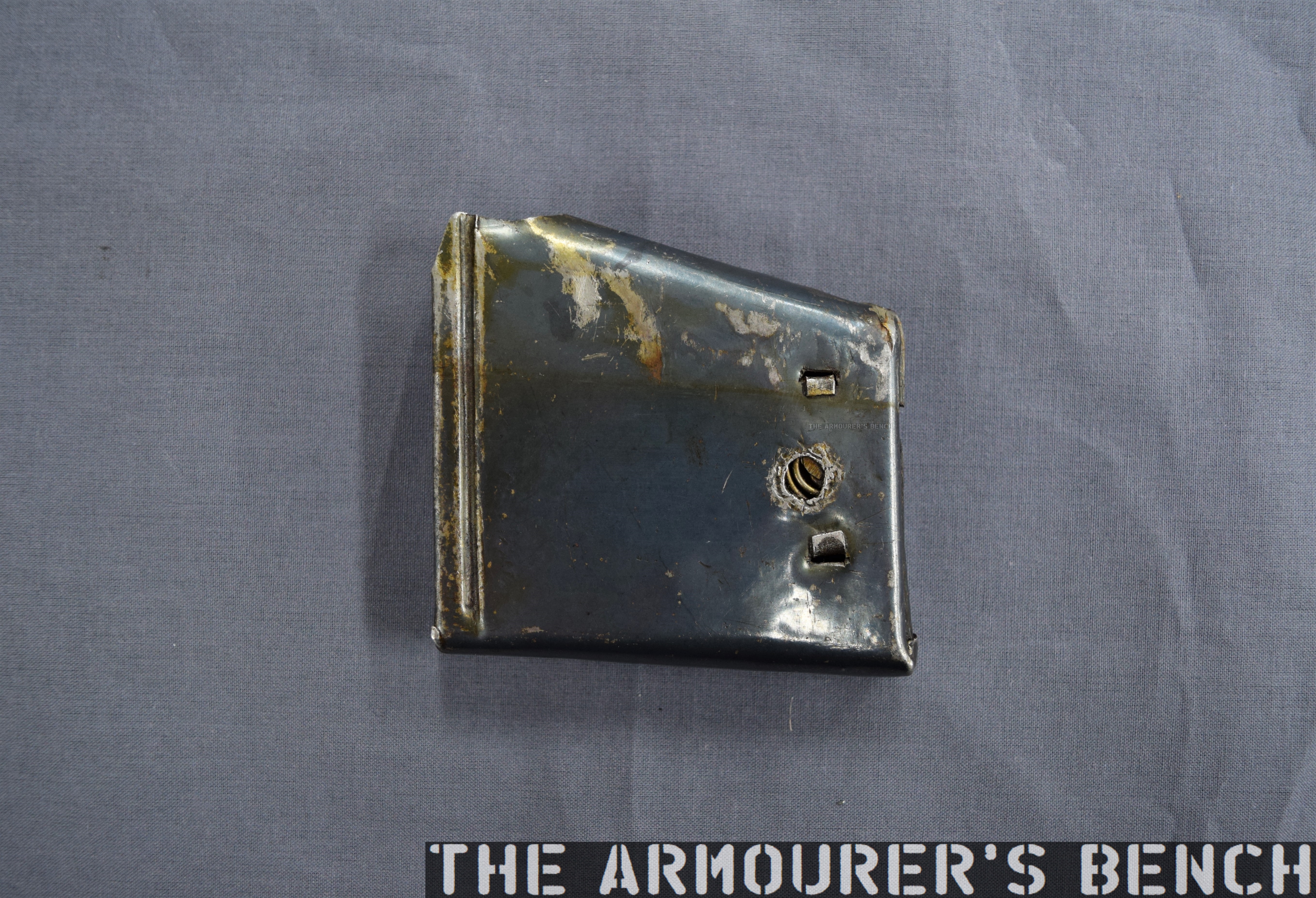
Close up of the weapon’s magazine housing, with salvaged Sterling magazine release button (Matthew Moss)
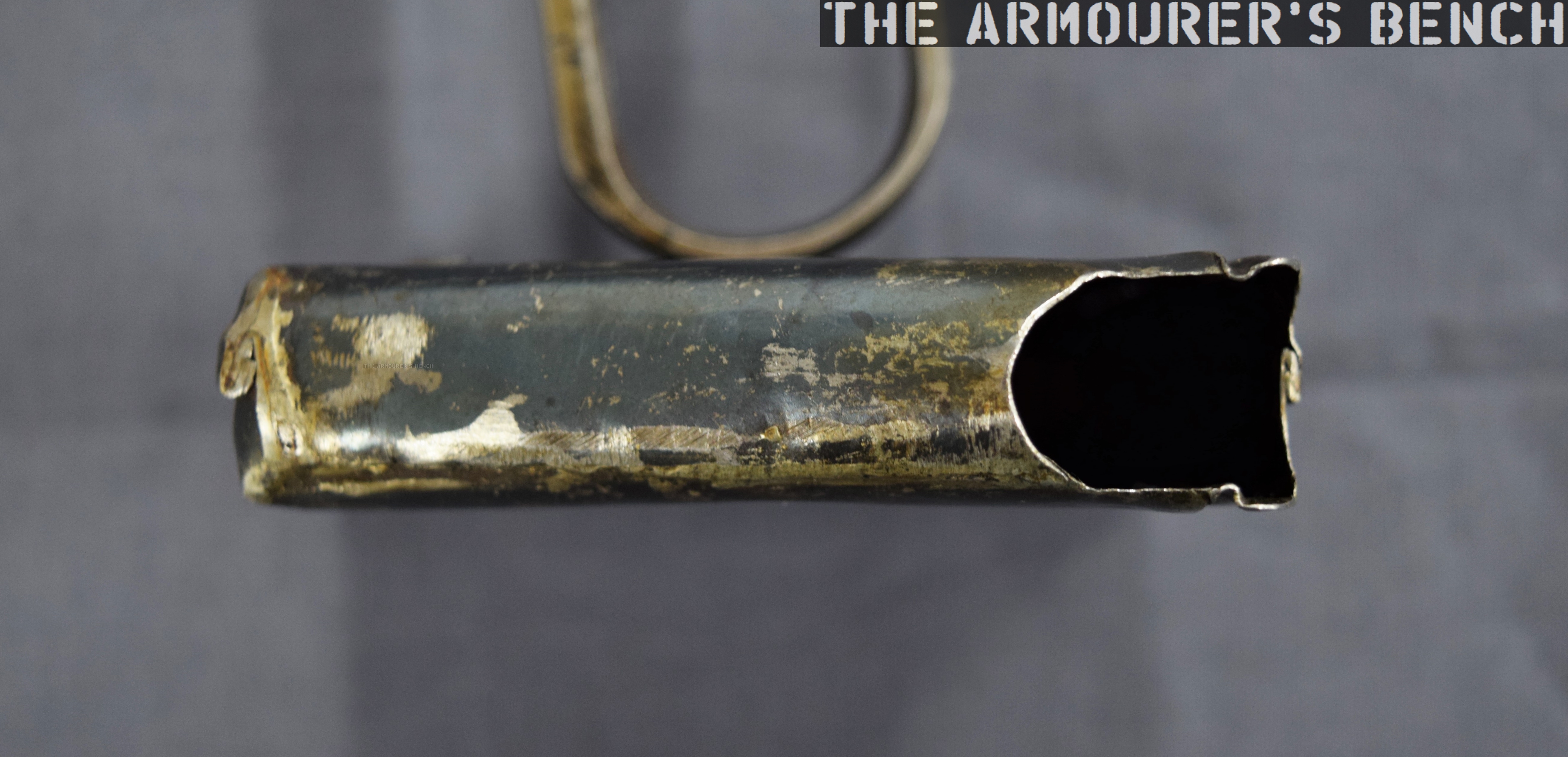
Another difference is the absence of a bayonet lug on the left side of the barrel shroud, and a much cruder fixed sight sat within a U-shaped piece of metal welded to the tube receiver – to act as a front sight protector. The factory-made Sterling’s front sight is adjustable and the sight protectors are folded forward and aligned across the tube receiver. The rear sight and its protectors appears to have sheared off at some point. The only marking on the weapon, ‘29992’, is crudely electro pencilled on the top of the magazine housing, where you’d normally see markings saying ‘Sterling Mk4’ or ‘L2A3’. When that crude serial number was added is unclear. The black paint on the receiver is wearing thin and we can clearly see some file marks in places.
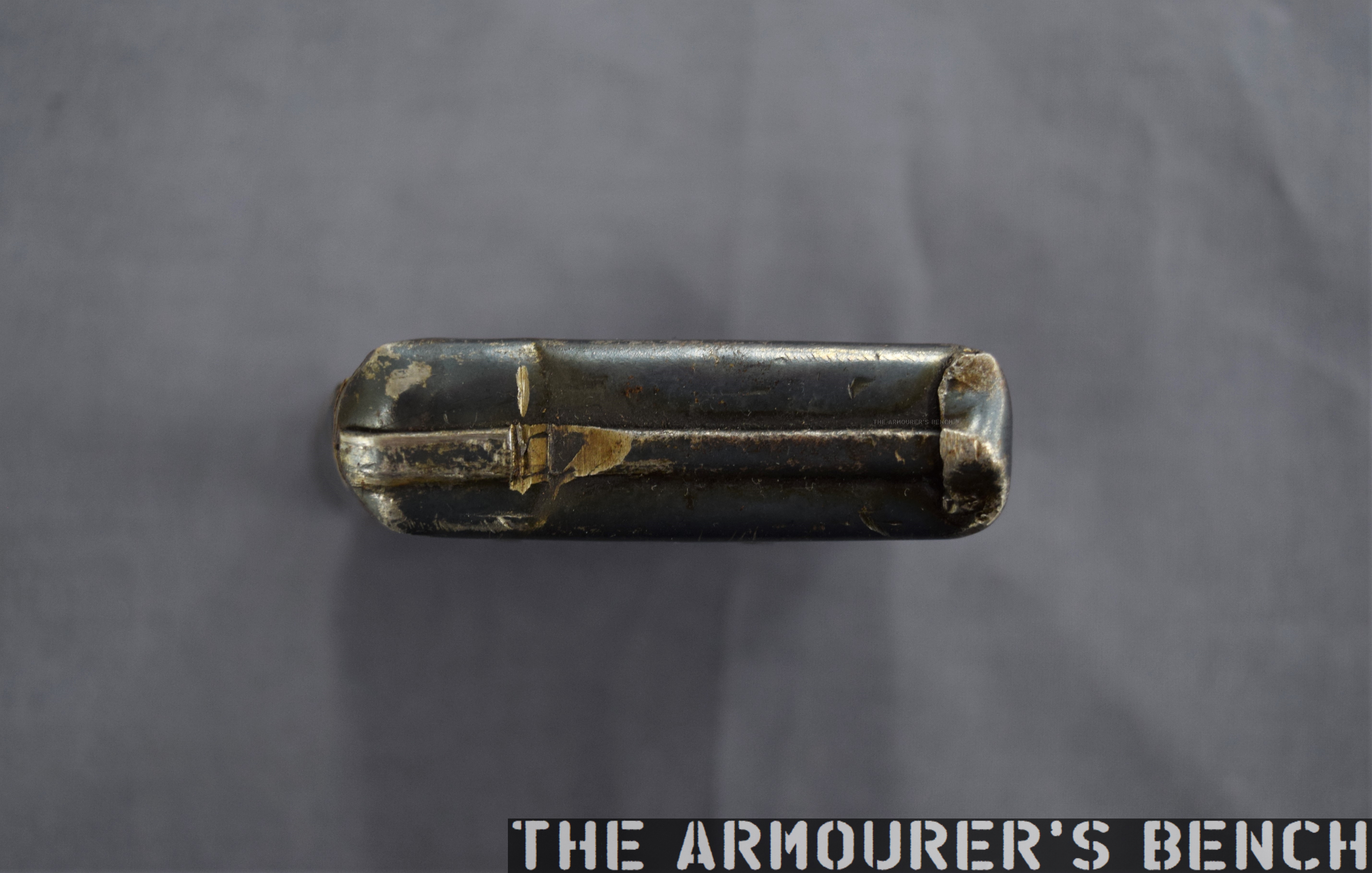
Hundreds of craft-made submachine guns were built to feed from Sterling and Sten magazines and there are numerous surviving examples of guns made from box tubing – often parts were clandestinely made in Northern Ireland’s factories and at shipyards like Harland & Wolf in Belfast – giving rise to the name ‘shipyard special’. Other nicknames included ‘rattlers’ and table leg guns.
Left side view of the Sterling clone (Matthew Moss)
The origins and story behind this particular weapon remain unknown, it is today part of a UK Ministry of Defence collection and said to have been found in Northern Ireland during the Troubles. Regardless it’s a very interesting piece of clandestine engineering which shows considerable skill in its assembly. Which is unsurprising as there are numerous accounts of skilled machinists working on illegal firearms parts during the period.
If you enjoyed this video and article please consider supporting our work here. We have some great perks available for Patreon Supporters. You can also support us via one-time donations here.Thank you for your support!
Bibliography:
The Northern Irish troubles | This Week | 1972, Thames TV, (source)
Terminal Effects: The Guns of the Loyalist Paramilitaries, Balaclava Street, (source)
Improvised Weapons of the Irish Underground (Ulster), D. Shea, Small Arms Review, (source)
Beyond State Control: Improvised and Craft-produced Small Arms and Light Weapons, G. Hays and N.R. Jenzen-Jones, Small Arms Survey, (source)
By 1895 Winchester had been considering a slide-action rifle for some time, in 1882 William Mason had begun work on one (US Patent #278987) to counter Colt’s slide-action Lightning only to drop it. Finally in 1890, Winchester introduced a slide-action .22 calibre rifle developed by John Browning. The Model 1890 became extremely popular.
Between 1887 and 1895 Browning patented four slide-action rifle designs. The first of these, US patent #367336, was granted in July 1887, this was followed in 1888 by US patent #385238. In September 1890, the Browning brothers were granted US patent #436965, which along with the previous 1888 patent protected what became the Model 1890. Three years later Winchester introduced the Model 1893 pump action shotgun, that would eventually evolve into the famous Winchester Model 1897.
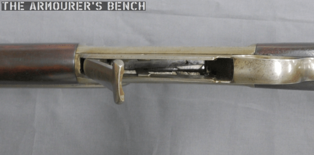
Right-side close up of the rifle with its action open (Matthew Moss)
Finally, April 1895, Browning filed a patent for a design for a .30 calibre rifle which was granted in September 1895 (US patent #545672) This patent covers the rifle we’re examining here. The rifle itself is a slide or pump action in long barrelled configuration which Winchester described as a ‘Musket’.
The September 1895 slide-action design was purchased by Winchester but like so many other Browning designs, it never entered production and Winchester purchased the design purely to secure it and prevent other rival manufacturers picking it up. Winchester instead went with a lever-action design, patented in November 1895 (US #549345), which became the famous Winchester Model 1895.
A left-side view of the rifle’s receiver with Browning’s patent overlaid (Matthew Moss)
The September 1895 slide or pump-action rifle design had a laterally camming locking breechblock. As we can see, externally Browning’s toolroom prototype looks somewhat similar to the contemporary Winchester Model 1895, with a single-stack integrated box magazine but with a pump sleeve rather than a lever.
An action-bar connects the slide/pump to the front of the breechblock/bolt carrieron the right-hand side of the rifle. The slide handle itself is made of a U-shaped piece of metal which wraps around the rifle’s forend. The slide has been roughly cross hatched to improve grip. There is a channel cut into the furniture for the action arm’s attachment point to travel. The slide is attached to the arm by a pair of screws.
A close up of the rifle’s slide/pump handle (Matthew Moss)
However, Browning developed this prototype to allow loading of the magazine from below rather than through the top of the receiver. He added a hinged floor plate, with a spring loaded follower, that allowed loose rounds to be dropped into the magazine and then closed.
As we open the magazine, hinging the cover plate down, we see the carrier flip down against the plate to allow loading. The rifle was designed to be loaded from below with the bolt forward.
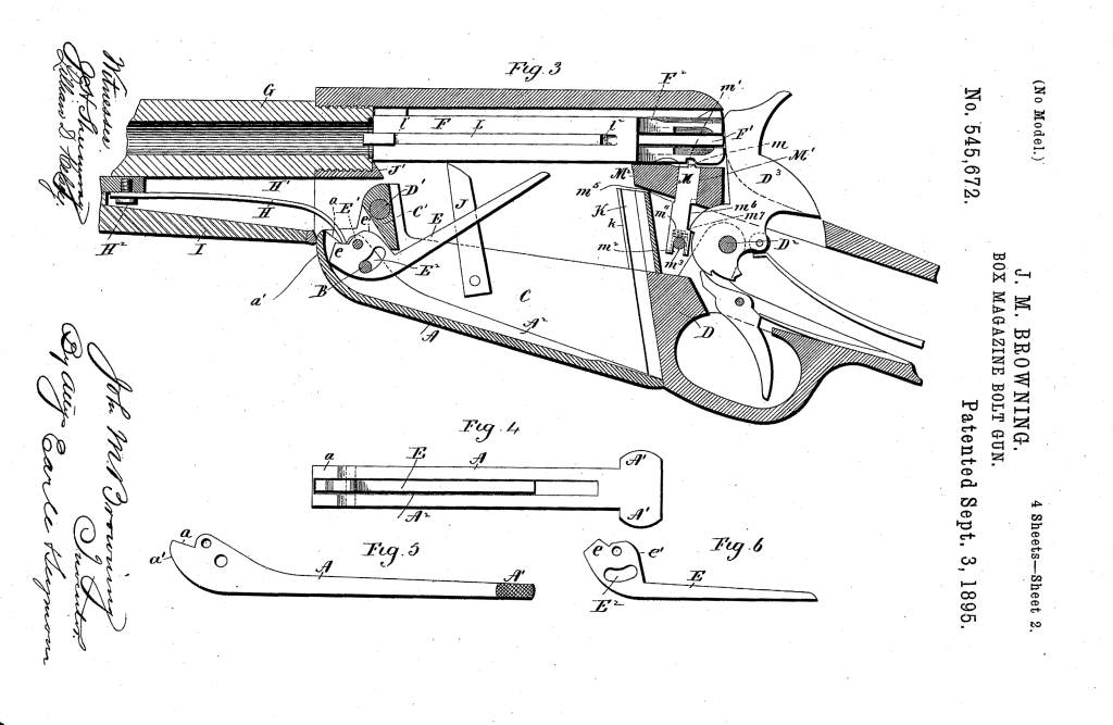
Browning’s September 1895 patent (US Patent Office)
In the patent description Browning explained that his aim was to improve breech-loading box-magazine firearms by designing:
“…a simple, compact, strong, highly effective, and safe gun, containing comparatively few parts and constructed with particular reference to provision for charging the box-magazine with cartridges from the bottom of the frame of the arm while the breech-bolt is in its closed position, so that the arm may be charged without operating its action mechanism or disturbing the cartridge in the gun-barrel, if one is there.”
Browning’s September 1895 patent (US Patent Office)
From the original patent drawings we can see the flat spring which acted on the carrier running below the barrel, ahead of the magazine. Inside the magazine are a pair of what Browning refers to as ‘spring fingers’ these act on the cartridges inside the magazine and keep them properly aligned, seen here in Fig.7 of the patent. In Fig.8 we can see what Browning calls a ‘box-like guideway’ which guide the rims of the cartridges, “preventing the cartridges from being displaced while being fed upwards.”
The rifle’s breechblock locked into a recess in the left side of the receiver, tilting at an angle with the rear of the breechblock canting to the left. When the pump handle was pulled rearwards the breechblock cammed laterally to unlock the action, extracted and ejected any spent casing and when the slide/pump was returned forward a new cartridge was picked up from the magazine, chambered the breechblock locked again ready to fire. The rifle’s hammer was cocked by the rearward movement of the breechblock.
A left-side view of the rifle with its action open, note the complex machining on the rear of the breech bolt (Matthew Moss)
Externally, the slide-action’s receiver looks similar to that of the production Model 1895 but internally they are very different. The action is certainly less open than the Model 1895’s but the lateral locking mechanism is less robust. Additionally, with no lever, as in the Model 1895, the slide-action rifle lacks the safety mechanism which prevents the action from opening accidentally.
A view inside the open magazine with the floorplate hinged open (Matthew Moss)
The model is in the white and while externally the machining and tool work is very neat, inside the action we can see where the cuts in the receiver wall have been more crudely made. In terms of design, the slide-action prototype was certainly simpler and had fewer working parts than the Model 1895 lever-action.
Winchester purchased the .30 calibre slide-action design but never produced it, it is believed that only Browning’s prototype was built to prove the concept. The prototype was part of Winchester’s collection and may now be found at the Cody Firearms Museum.
The Walther P5 was developed in the mid-1970s as an response to the West German police’s continued search for a 9x19mm service pistol to replace the older smaller calibre pistols then in service, like the Walther PP. It was developed to fit the new police specification for a small, handy pistol which could be brought into action quickly. Walther’s design competed against pistols from Mauser, Heckler & Koch and SIG Sauer.
Walther P38 (Rock Island Auctions)
The P5′s design evolved from the P38, combining the lock work and dual recoil springs of the P38 (re-designated the P1 in 1963) with a shortened barrel and a full length slide. While a shortened P38k had been produced in the early 1970s, this was only an as an interim solution. The P38K retained the same slide and frame as the original P38s, but had the front sight mounted on the front strap of the frame and none of the pistol’s contours were rounded to aid drawing and returning to a holster. Only around 2,600 P38Ks were produced.
Following the attack on the 1972 Munich Olympics games West German police began the search for a new service police. Walther’s response, the P5, was introduced in 1978. The P5 is a locked-breech pistol and has double-action/single-action (DA/SA) trigger. It uses the same short-recoil operated system and locking mech as the P38. This means that the barrel and slide recoil together for a short distance before the locking block falls and allows the slide to continue moving rearward, ejecting a spent case and chambering a new round.
Walther P5 (Matthew Moss)
Walther moved the P5’s decocker from the slide to the frame and this also served as the slide stop and slide release. I would say that the P5’s decocker is easier to operate, with a shorter length of travel, than the SIG P6’s.
Following the West German police specification Walther designed the pistol to be safely and rapidly brought into action, and as a result dispensed the manual safety. Instead, the pistol could be carried in condition two – with a round in the chamber and the hammer down. This was safely achieved by some upgrades to the P5’s hammer and firing pin. There is a small recess in the pistol’s hammer for the firing pin. The firing pin only moves into alignment with the hammer surface when the trigger is pulled.
The P5 has a 3.5 inch (9cm) barrel and fed from an 8-round, single stack, magazine with a heel release. Like the P38 the pistol ejects to the left rather than the right. The P5 has a stronger and more durable fully enclosed slide which is contoured to aid holstering. The pistol has an alloy frame, with full-length slide rails and an enlarged trigger guard for use with gloves.
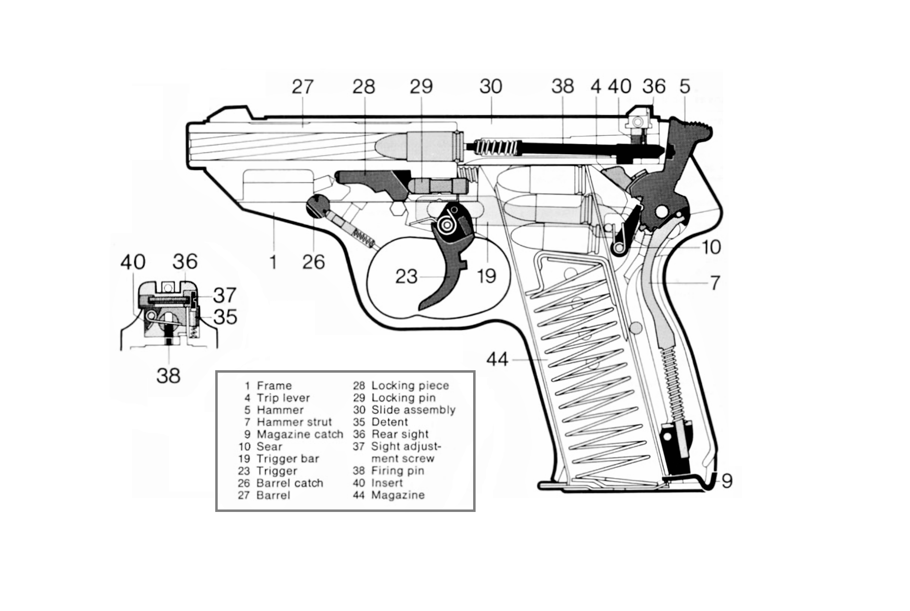
Diagram showing the P5’s parts and internal layout (Walther)
In addition to the P5, Walther also developed a compact model for plain clothes use which had a slightly shorter barrel (3.1 inches), slide and a truncated hammer. It was introduced in 1988 and had a lighter alloy frame with the P5 Compact weighing 750g (1.65lbs) rather than 795g (1.75lbs). While early production pistols retained the heel magazine release the majority had a thumb release. A small number of P5-Lang, long barrel target pistols were also produced in the late 1980s.
Disassembly is simple and comes directly from the P38. The slide is retracted a little until the barrel catch can be rotated. The slide and barrel can then be slid forward off the frame once the trigger is pulled.
The P5 proved to be an accurate and reliable pistol and once it was accepted by the police trials (along with the designs from Heckler & Koch and SIG-Sauer – the P7 and P6 respectively.) It was adopted by uniformed officers of Baden-Württemberg and Rhineland-Palatinate’s State Police – these pistols were marked ‘BMI’ for Bundesministerium des Innern – the Federal Ministry of the Interior. This pistol is a BMI-marked gun and dates from February 1983.
Walther P5 brochure cover (Walther)
It also became the standard issue sidearm of the Dutch police who purchased around 50,000 pistols, becoming Walther’s largest customer for the P5. The Dutch guns were later fitted with aftermarket Houge rubber grips and some changes to the hammer safety system were later made in the mid-1990s. The Dutch police retired the P5 in 2013 replacing it with the P99Q.
The P5 also saw some military sales with elements of the Portuguese Army adopting it and the P5 Compact was also adopted by the British Army. Selected in the late 1980s for issue as a personal protection side arm. It was designated the Pistol L102A1 and was extensively issued to British troops in Ireland for use while in plain clothes or off duty.
The P5 on screen: Sean Connery as James Bond in, the technically unofficial, 1983 Bond movie Never Say Naver Again. Roger Moore’s Bond also carried it in Octopussy (also in 1983)
While certainly one of Walther’s lesser known pistols the P5 is a well-made, well-designed duty pistol, with comfortable ergonomics – the fiddly magazine catch not withstanding – and the slide and decocker are very smooth to operate. The trigger pull in both the single and double action modes is also pretty good. Overall, around 100,000 pistols were produced before production came to an end in 1993.
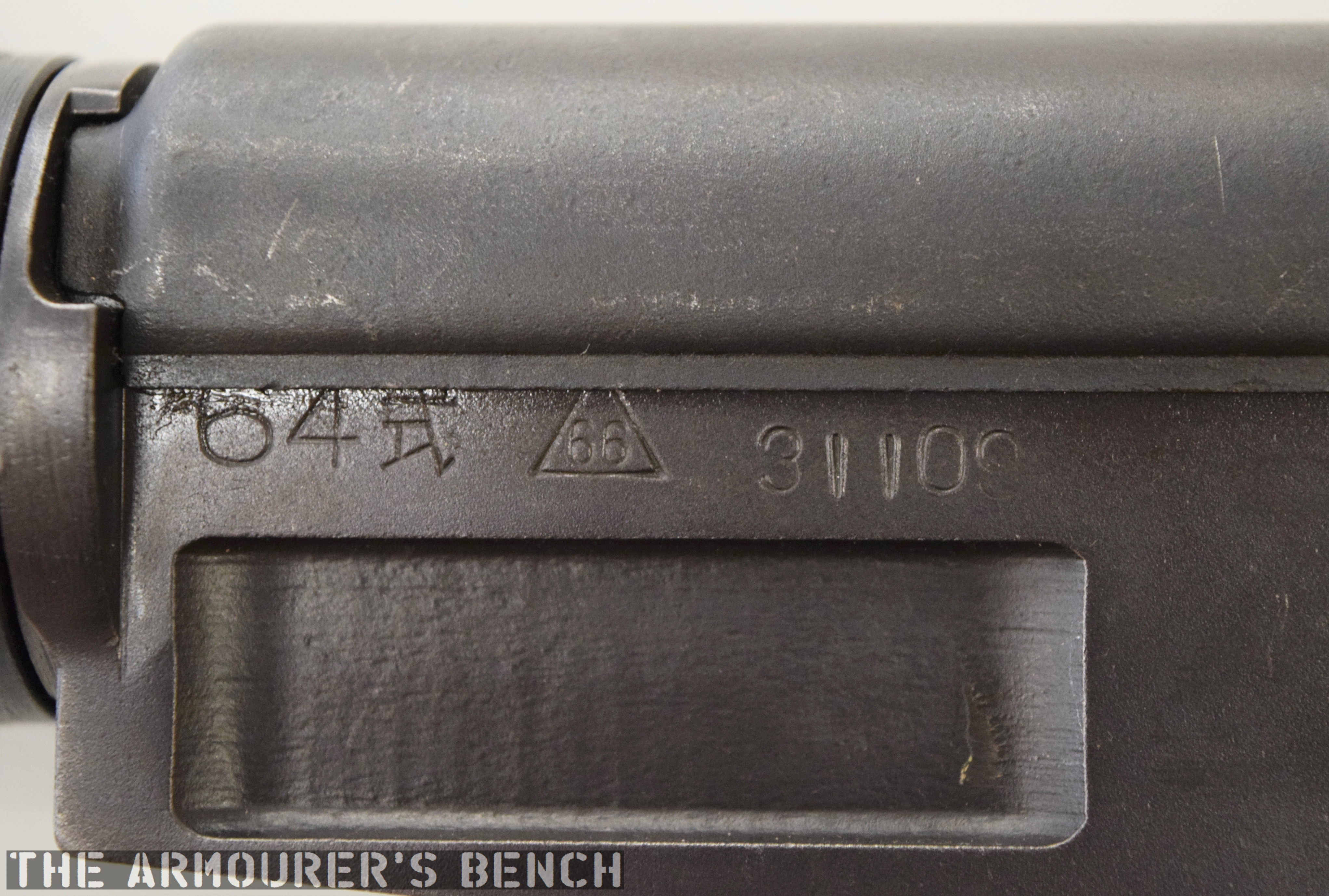
The Type 64 is an integrally suppressed submachine gun designed in China in the early 1960s, taking several design elements from other Combloc small arms. The guns were manufactured at one of China’s State Factories (with the factory’s ‘66’ in a triangle marking in the left side of the receiver – this indicates the factory number, although available sources differ on which it refers to, either 66, 626 or 366).
Right side of the Type 64, with stock folded (Matthew Moss)
Designed concurrently with the Type 64 suppressed pistol during the 1960s, the Type 64 SMG was developed for Communist China’s special forces for use in clandestine operations. Chambered in the standard 7.62×25 ComBloc pistol round, the Type 64 functioned best with Type 64 subsonic ammunition, a special subsonic spitzer projectile variation of the standard 7.62mm pistol round. It did not chamber the low power 7.65x17mm round used by the Type 64/67 pistols.
A close up of the weapon’s markings, including the State Factory 66 stamping (Matthew Moss)
The Type 64 fed from 20 or 30 round double stack magazines which were reportedly developed from or at least influenced by the Soviet PPS-43’s double stack, double feed magazines. The weapon used a conventional blowback action and fired from an open bolt. Its maximum effective range was approximately 200 metres with two position flip up sights ranging out at 100 and 200 metres.
The Type 64 had a milled receiver with lightening cuts and weighed in at 7.6lb or 3.5kg unloaded. It took its bolt from the Russian PPS-43 submachine gun and a trigger group inspired by the ZB vz.26 light machine gun’s, which was well liked by the Chinese military.
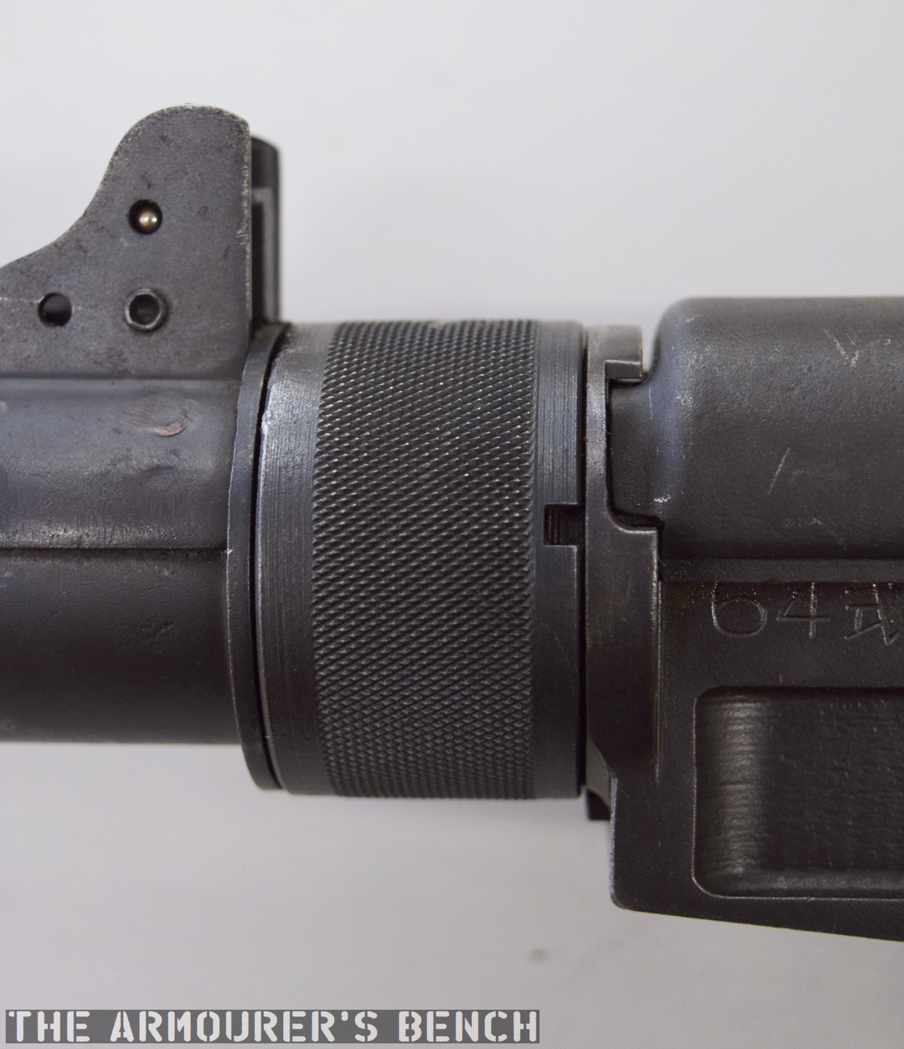
The suppressor housing is unscrewed at the trunnion with an interrupted thread (Matthew Moss)
The Type 64 shared a number of external similarities with the standard Type 56 AK-clone including its pistol grip, safety lever and under-folding stock (which is similar but slightly different to the Type 56-I’s under-folding stock).
The Type 64’s fire selector (Matthew Moss)
The weapon has a number different controls including a conventional AK-style safety-come-dust cover, on the right side of the receiver – which blocks the travel of the bolt. On the opposite side of the receiver it has a two-position fire selector for semi and full-auto – you can just about reach these when the stock is folded. The forward position is for semi and the rearward position is full-auto. Finally, the 64 also has an additional trigger block safety, taken from the SKS, which pivots forward to prevent the trigger from being pulled.
A close up of the magazine release, trigger block safety and lever safety (Matthew Moss)
According to a report written in October 1971, by the Small Arms Systems Lab of the US Army Weapons Command Research and Engineering Directorate, the weapon has an extremely high rate of fire of over 1,300 rpm.
A cyclic rate that high was the result of a combination of back pressure from the suppressor, the ammunition used and its blowback action. The Type 64’s chamber was fluted with three longitudinal cuts to aid extraction at its high rates of fire. It should be noted, however, that the 1971 US army tests were carried out with standard velocity ammunition – rather than the specialised subsonic Type 64.
The Type 64 with stock deployed, left & right profiles (Matthew Moss)
The top cover is removed by pushing in what at first appears to be a spring-loaded detent, but is actually the recoil spring guide rod. The front of the top cover is held in the receiver by a lip which fits into a slot just above the breech. The top cover itself is a thin piece of stamped sheet metal with the serial number stamped at the rear.
With the receiver cover removed and the action cocked. The Type 64 fires from an open bolt. Note the buffer at the rear of the receiver (Matthew Moss)
With the top cover removed we can see inside the action. The 64 has a single recoil spring held in place by a guide rod. At the rear of the receiver is a small plastic buffer, designed to both soak up some of the recoil energy and to help reduce action cycling noise. There is an ejector on the left side of the receiver and guide rails along which the bolt moves. To remove the bolt it is pulled fully to the rear and then tilt it upwards.
A close up of the bolt face (Matthew Moss)
The Type 64 is a pretty compact weapon despite the length of its suppressor. It has an under-folding stock, with two spring-loaded buttons at the rear of the receiver which have to be pushed in to fold and unfold the stock. When folded the weapon is 25in (or 63.5cm) long, with the stock adding 8 inches when it is deployed. The weapon can be used with the stock folded, although some of its controls are partially obscured.
The suppressor is contained by a housing which attaches to the receiver by an interrupted thread. The Type 64’s barrel was ported with 36, 3mm vents at the muzzle-end while the suppressor has 12 metal dished baffles held captive on a pair of guide rods. The weapon’s sights are mounted on the suppressor housing which attaches to the receiver by an interrupted thread. Sadly, I didn’t have time to strip the suppressor itself but the photos below, from my friend Chuck over at Gunlab, show the Type 64’s ported barrel and baffles well.
With the suppressor housing and baffle system removed. Note the series of holes in the barrel (GunLab)
The 1971 Small Arms Systems Lab report found that the audible report of the gun, was 150db at the rear of the receiver and 157db 12 feet down range, however, this is probably not the best indication of the Type 64’s capabilities as the report states that the gun was tested with Chinese Type 51 standard velocity 7.62x25mm ammunition. Ideally, the weapon would have been used with subsonic Type 64 ammo specially developed for China’s suppressed pistol-calibre weapons. Chinese sources reportedly put the weapons noise level at 84db when using subsonic ammunition. The US report did note that while its noise suppression wasn’t outstanding, it very effectively hid its muzzle flash.
The baffle system held together a pair of guide rods (GunLab)
It appears to have been primarily used by Chinese scouts and special forces and saw action during the 1979 Sino-Vietnamese War. In the late 80s the Chinese replaced the Type 64 with the suppressed version of the Type 85 submachine gun, also chambered in 7.62x25mm, which used the same magazines, the Type 85 had a tube metal and stamped receiver which was simpler to manufacture than the 64’s machined receiver. The Type 85 has subsequently been superseded by guns like the bullpup Type 05.
Special thanks to the collection that holds this weapon for allowing me to take a look at it. As always guys thank you for watching. If you enjoyed the video please share it with friends and help us
‘Technical Notes: Chinese Communist 7.62mm Type 64, Silenced Submachine Gun’, US Army Weapons Command Research & Engineering Directorate Small Arms Systems Laboratory, J.J. Boccarossa, 27/09/1971
Secondary Sources:
Chinese Type 64 SMG, Small Arms Review, F. Iannamico (source)
Type 64 submachine gun (PR China), Modern Firearms, (source)
Chinese Type 64 suppressed SMG, ForgottenWeapons.com (source)
The 1890s were one of John Browning’s most prolific periods, during which he developed a host of firearms which would never actually see production. Here, we’re lucky enough to be able to examine one of those prototypes that were never produced. Dating from 1892, this rifle departs from Browning’s earlier lever-action rifle designs in a number of interesting ways. Perhaps the most interesting aspect of the design is its use of en bloc clips, instead of the tube magazine traditionally used by Winchester’s repeating rifles. John Browning, and his brother Matthew, filed the patent covering the design in June 1892.
Right side of the rifle, note its ‘musket’ configuration (Matthew Moss)
The rifle is in what is typically referred to at the time as a ‘Musket’ configuration, signifying that it is a military long-arm. It has a long 32.5 inch barrel, which is held in place by two barrel bands. Overall the rifle is around 50 inches in length and weighs just over 9lbs. The rifle is chambered in a .30 calibre cartridge, likely the then new .30-40 Krag round given its proposed market. It has a ladder-style rear sight with range graduations from 100 to 1,000 yards.
Browning’s patent drawing showing the rifle’s action (US Patent Office)
Okay, let’s take a closer look at the prototype. During the 1890s Browning experimented with a series of magazine systems including an en-bloc clip system. This rifle uses a 5-round magazine which is fed from an en-bloc clip. The idea of an en-bloc clip was relatively new with Ferdinand Mannlicher patenting the idea in the 1880s and using it in his Model 1886 and 1888 rifles. It is unclear if Browning was familiar with Mannlicher’s system but the two are very similar. If you’re unfamiliar with en bloc clips it means that the cartridges are loaded into the weapon in the clip rather than stripped from the clip.
A look at the ejection port for the en-bloc clip (Matthew Moss)
Browning’s prototype holds five rounds in its clip, which from patent drawings we can see was not reversible. Sadly, we don’t have an example of Browning’s clip to examine but his 1892 patent (see above) gives us a good idea of what it would have looked like. It clearly has a cut at the top of the clip which appears to have been used to help guide the round up into the chamber.
Rounds were pushed up into the action by a follower arm which was actuated by a v-spring located at the front of the magazine housing. The bottom of the fixed magazine housing has a cut-out corresponding to the clip to allow it to fall or be pushed clear by a new clip once it was empty.
The rifle’s lever fully-forward with its action open and striker cocked (Matthew Moss)
The rifle also departs from the traditional hammer system and uses a striker-fired action. From the patent drawings we can see how the rifle’s striker worked, with a coil spring extending into the stock and a sear holding the striker to the rear. The striker is made up of two pieces with the striker hitting a long firing pin inside the bolt.
The striker has, what the patent refers to as, a ‘thumb piece’ to enable re-cocking and to indicate if its cocked or not. The striker was cocked by the cycling of the lever and held in place by the trigger sear.
A view inside the action with the bolt partially retracted before it moves down and back into the rifle’s wrist (Matthew Moss)
The lever was held in the close position, preventing out of battery discharges, by what Browning’s patent calls a downward-projecting dog, which projected through a small hole in the trigger assembly link and locked into a catch in the front of the lever loop.
The use of a striker, rather than an exposed hammer, allows the rifle bolt’s travel to be enclosed rather than have the bolt project out of the rear of the receiver, as in previous Winchester lever-actions, we can see that this rifle’s bolt slides back at an angle partially down into the wrist of the stock. This is arguably more ergonomic and potentially helps to prevent ingress of dirt.
The first half of the lever’s travel pulls the bolt to the rear, while the second part cocks the striker. An arm extending from the lever pushed the bolt rearward until the trigger sear was engaged. In order to give the lever enough throw to open the action far enough to allow a round to be loaded the trigger mechanism has to be pivoted out of the action, much like the earlier Winchester 1886.
The bolt has a pair of trunnions which project from the sides of the bolt, these run inside longitudinal grooves either side of the receiver, while the rear of the bolt is free to angle up and down as it cycles. The action is locked by the rear of the bolt secured against the rear of the receiver, rather than with a rising locking bolt.
Left side of the rifle (Matthew Moss)
During the period Browning was also working on other lever action and, even more unusual, so-called pull-apart actions as well as various magazine types including a revolving magazine, stripper-clip box magazines and of course as we’ve already seen a detachable box magazine-fed rifle. The 1890s were a truly prolific period for Browning.
The design was purchased by Winchester and the Brownings’ patent was granted in November 1892. The gun, like many of Browning’s other designs of the period, never saw production. Making this rifle a rare one-of-a-kind prototype. It’s an elegant design and the action is smooth. When Winchester did finally seek to produce a military lever-action they chose another of Browning’s designs which retained his traditional rear-locking bolt, which became the Model 1895.
This rifle is a unique prototype and it was an honour to examine it. It’s now on display at the newly refurbished Cody Firearms Museum at the Buffalo Bill Centre of the West. Our thanks to the museum for allowing us to film items, like this one, from the museum’s collection.
We’re proud to present our very first bayonet-centric episode. Vic takes a look at a bayonet for a Sudanese contract AR-10 as part of his ongoing Surplus Zone series. While a rather rare bayonet this example has some interesting features.
In 1958 the Sudanese Military contracted with Samuel Cummings company Interarmco, to supply 2,508 AR-10 Battle Rifles. 2,500 standard rifles and 8 adapted to mount optical sights as sniper rifles.
One of the requirements for the Sudanese rifles were that they were to be able to mount bayonets, something the AR-10 did not have a capability to do in its then current form. This inability to mount a bayonet was overcome by a rather simple and ingenious addition to the rifle. A cast and machined sleeve was fitted over the barrel between front sight base/gas block and the flash hider. This was pinned to the barrel just forward of the front sight base/gas block. It had machined into the underside of the bayonet adaptor a longitudinal rail to which the bayonet could be attached. This is the same interface as seen on WWII German issued Kar98K rifles, the significance of which will become clear!
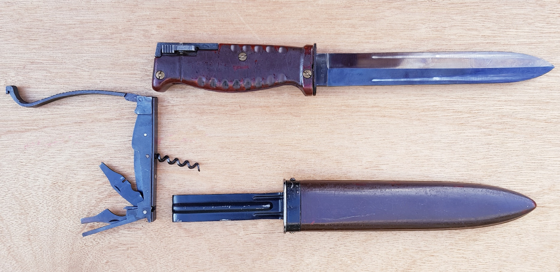
It is uncertain why Interarmco chose the design of bayonet which they did. It would have been quite an expensive and complex one to manufacture but it is obvious that it is based upon the late WWII SG-42 bayonet come utility/fighting knife. The Sudanese contract AR-10 bayonet has a more symmetrical blade than that of the SG-42 and has no ‘blood groove’ (properly known as a fuller) which hints at the fact that it is seen more of a utility knife than as a ‘cut and thrust’ fighting knife/bayonet.
Sudanese contract AR-10 bayonet
It has been established that the SG-42 was manufactured by Waffenfabrik Carl Eickhorn in Solingen, Germany (determined by its cof marking / WaA19 inspection code), whereas the toolkit was made by Robert Klaas of Solingen (inspection code: ltk). Inside the bayonet’s grip are a number of tools which detach from the grip and can be used for rifle maintenance. The tools also include a bottle opener and a corkscrew. Inside the toolkit stored in the bayonet’s grip are a number of tools which detach from the grip and can be used for rifle maintenance. The tools also include a bottle opener and a corkscrew.
In regard to the AR-10 Sudanese bayonet, the Eickhorn company does not deny being the manufacturer of the Sudanese contract bayonet, they simply cannot confirm that they were the maker, since all relevant factory records have been lost!
In the Dutch AR-10 archives, Interarmco (i.e. Samuel Cummings) does not disclose the name of the manufacturer, but refers only (in the pertinent correspondence with A.I.) to “the Solingen manufacturer” of this knife-bayonet for the Sudanese contract.
Check out Vic’s earlier Surplus Zone videos hereand his special series on the AR-10 here.
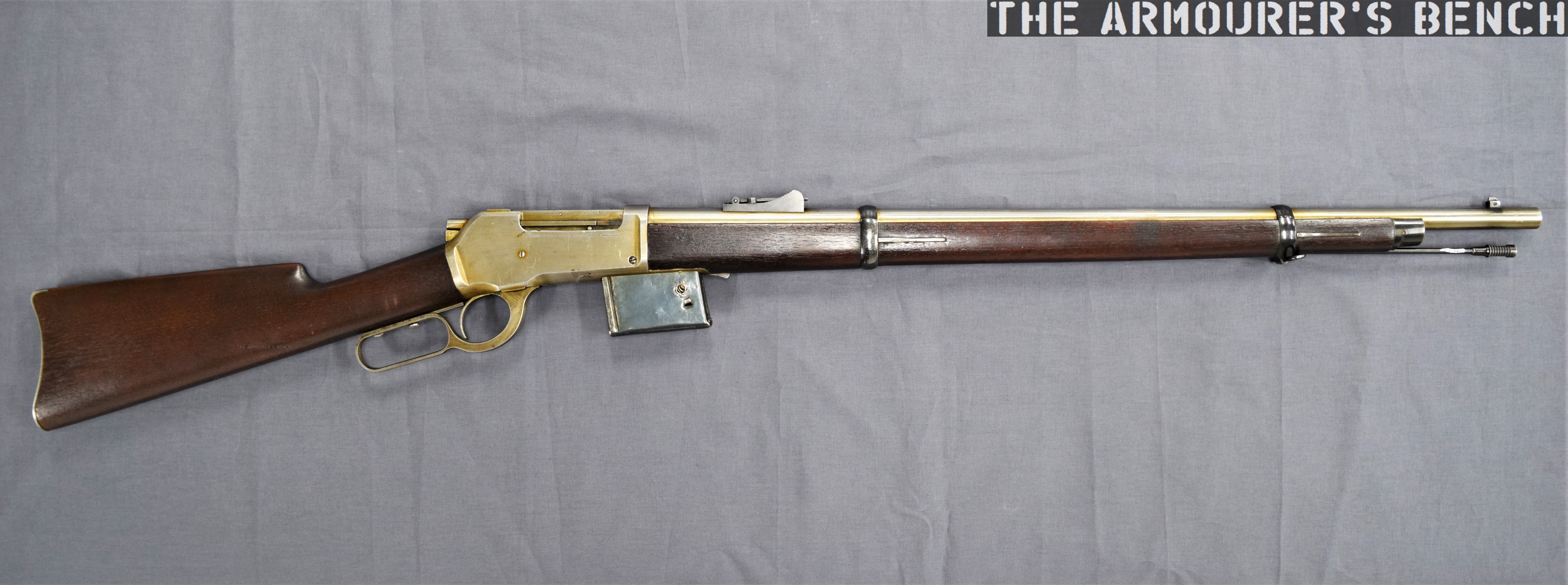
The rifle we’re examining is one of dozens of designs sold by the Brownings to the Winchesters Repeating Arms Company during their long relationship. This design dates from the early 1890s and represents one of Browning’s numerous attempts to move away from the tube magazine-fed designs favoured by Winchester.
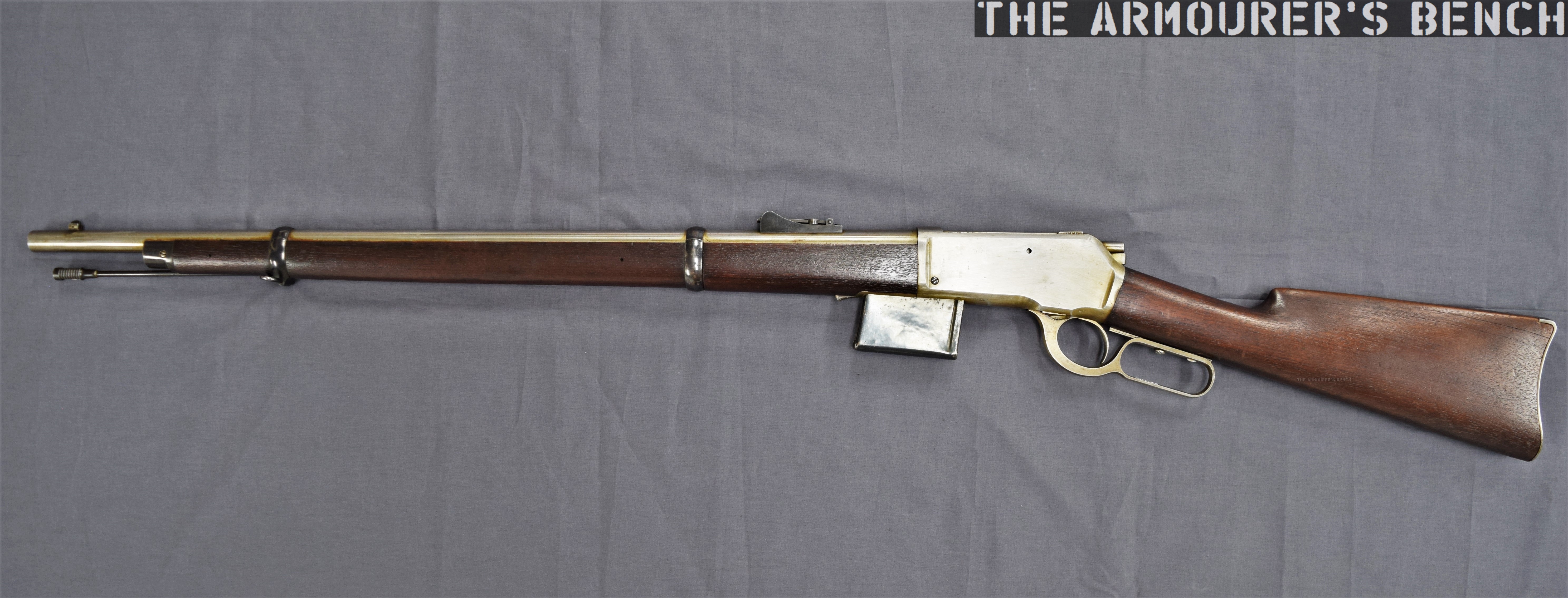
The prototype is based around the lever-actuated vertically sliding locking block patented by Browning in May 1884 and first used by Winchester in the Model 1886. The rifle itself is in the ‘military musket’ configuration with full-length handguards, military sights, a cleaning rod and able to mount a bayonet.
Right side of the rifle (Matthew Moss)
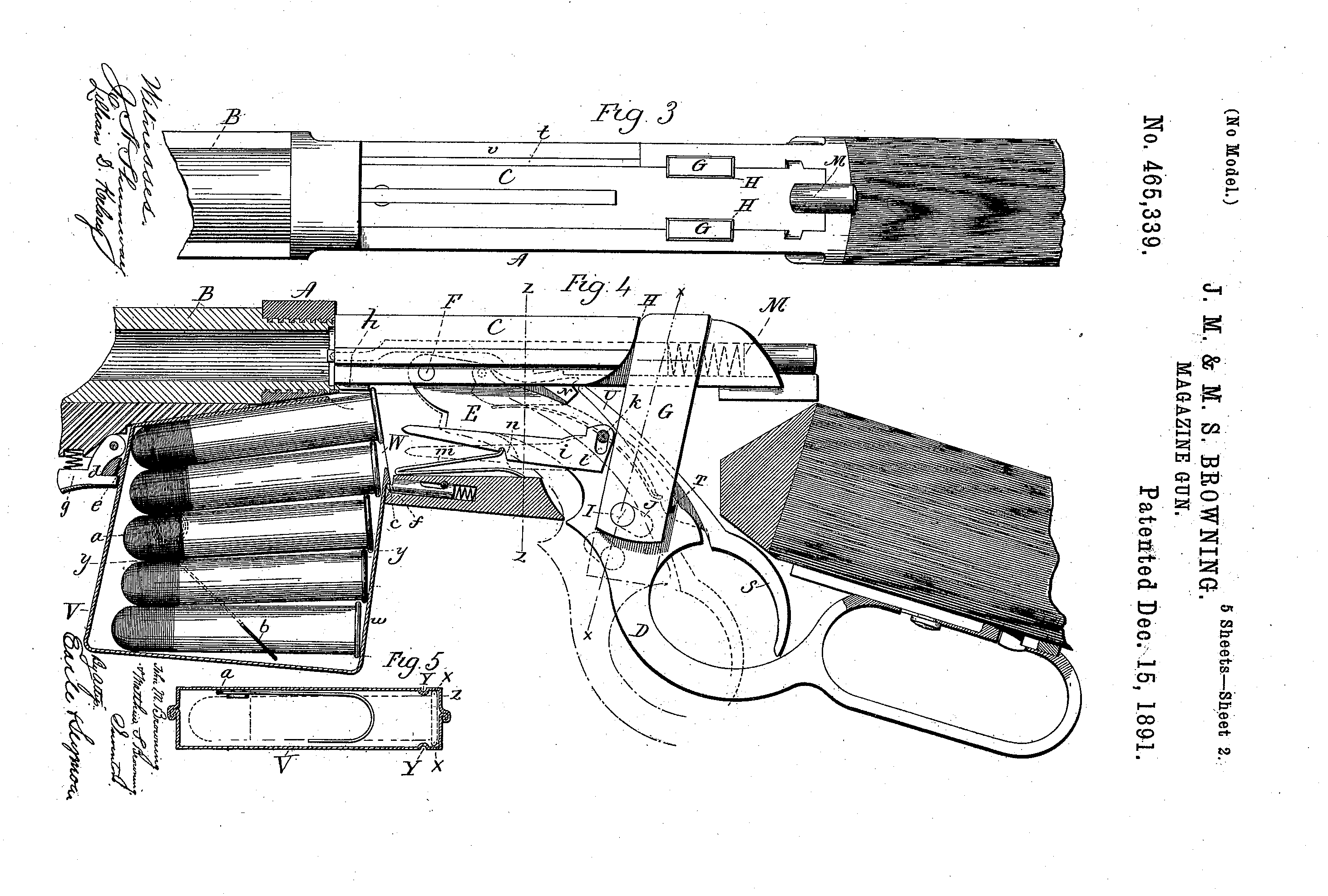
The rifle is chambered in a .45 calibre cartridge, likely .45-70, and weighs just over 9lbs. Browning patented the design of the rifle and magazine in August 1891, with the patent being granted in December (US #465339). It is attributed to John Moses Browning and his younger brother Matthew S. Browning.
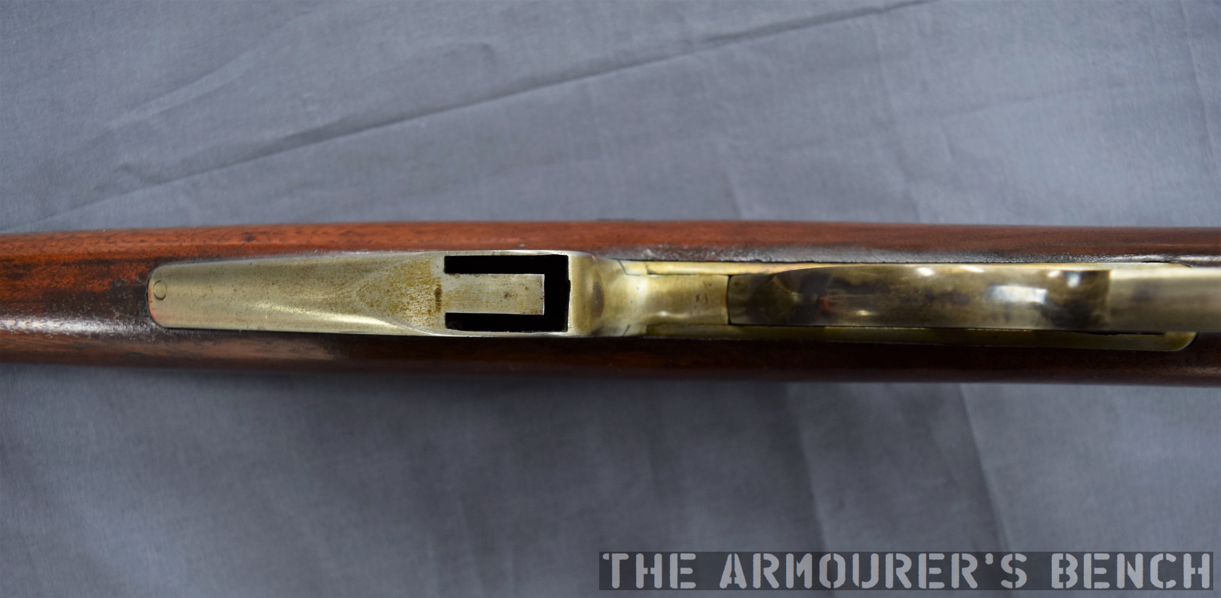
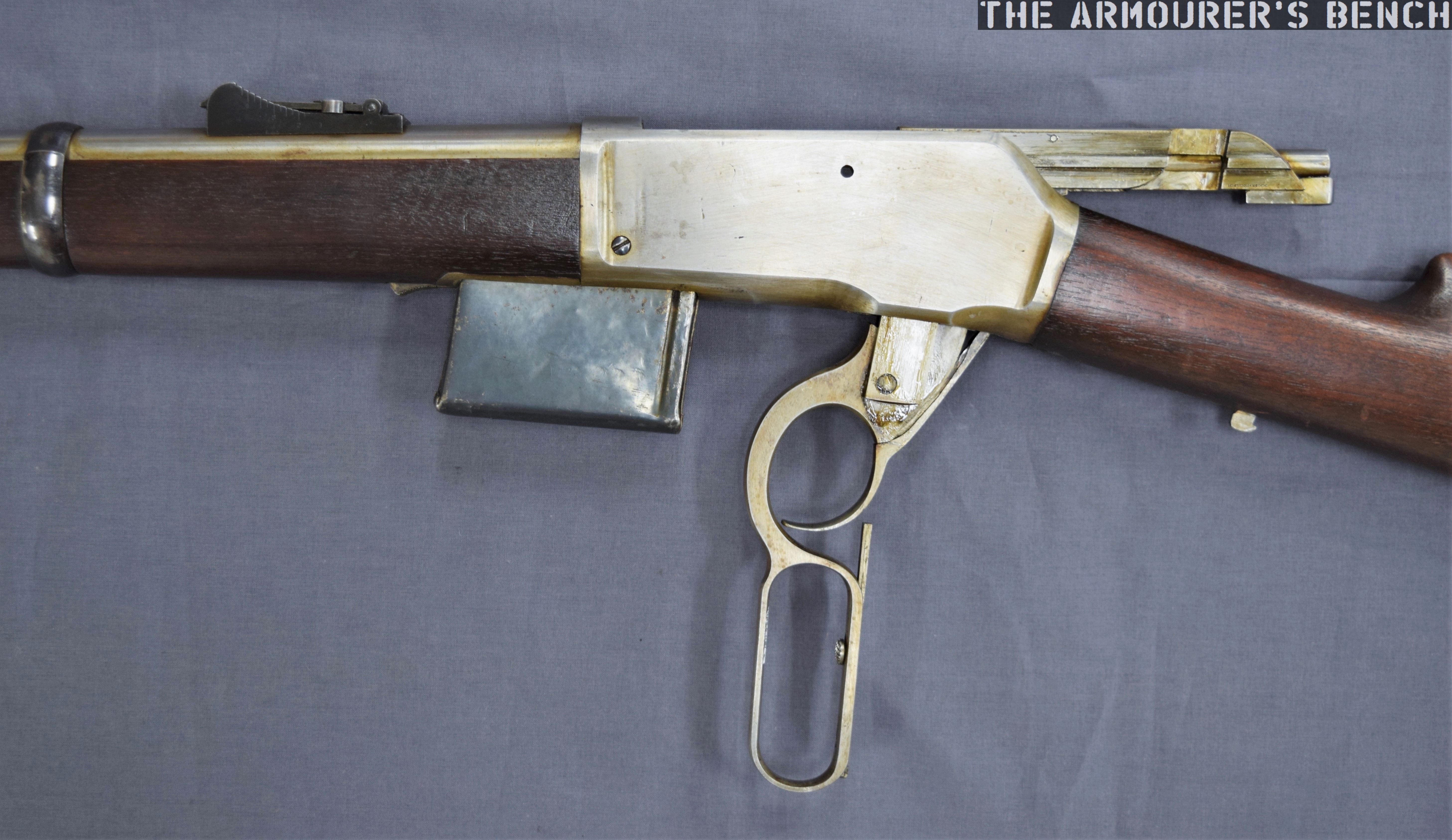
The most interesting feature of the rifle is its detachable box magazine. The magazine is held in place by a spring-loaded catch at the front of the magazine which locks against a tab in the magazine’s wall.
A close up of the magazine well, note the added metal lip of the front of the well, not a part of the receiver (Matthew Moss)
It differs from the box magazines previously developed by James Paris Lee, which Lee begun developing in the mid-1870s (see examples listed below). It’s a simple design with a follower powered by a coil spring. The prototype mag itself is made from pressed metal and is held together with some rough welds. Unlike the magazines we’re familiar with today, the top of the Browning’s magazine is almost entirely enclosed with only a small opening at the rear. The rounds would be loaded nose-first with their rims sliding into the channel at the rear of the magazine.
Close up of the magazine removed from the rifle – right side (Matthew Moss)
A view of the top of the magazine with the small opening and notch for the cartridge rime visible (Matthew Moss)
The single-stack magazine appears to hold around five rounds, with Browning’s patent supporting this. The position of the magazine, in front of the action – not below it, is a hint at how it worked. An almost fully enclosed magazine does have its advantages – it would have prevented dirt from entering the mag and it also overcame the need for feed lips which were susceptible to damage, one of the elements which took Lee some time to perfect.
A close up of the front wall of the magazine, note the locking notch (Matthew Moss)
So How Did The Magazine Work?
There is a shoulder on the underside of the bolt which caught the rim of the cartridge which was protruding from the magazine. The bolt pulled the cartridge backwards, out of the magazine and onto a cartridge lifter. As the lever reached its full forward travel the lifter then elevated the round up into line with the breech. When the lever was cycled back again the round was pushed off the lifter and chambered, just as in a normal tube-fed Winchester. As the lever reached the end of its return travel the locking block rose to locked the action.
The Browning’s 1891 patent for the magazine, note ‘h‘ is the shoulder which pulled rounds out of the magazine (US Patent Office)
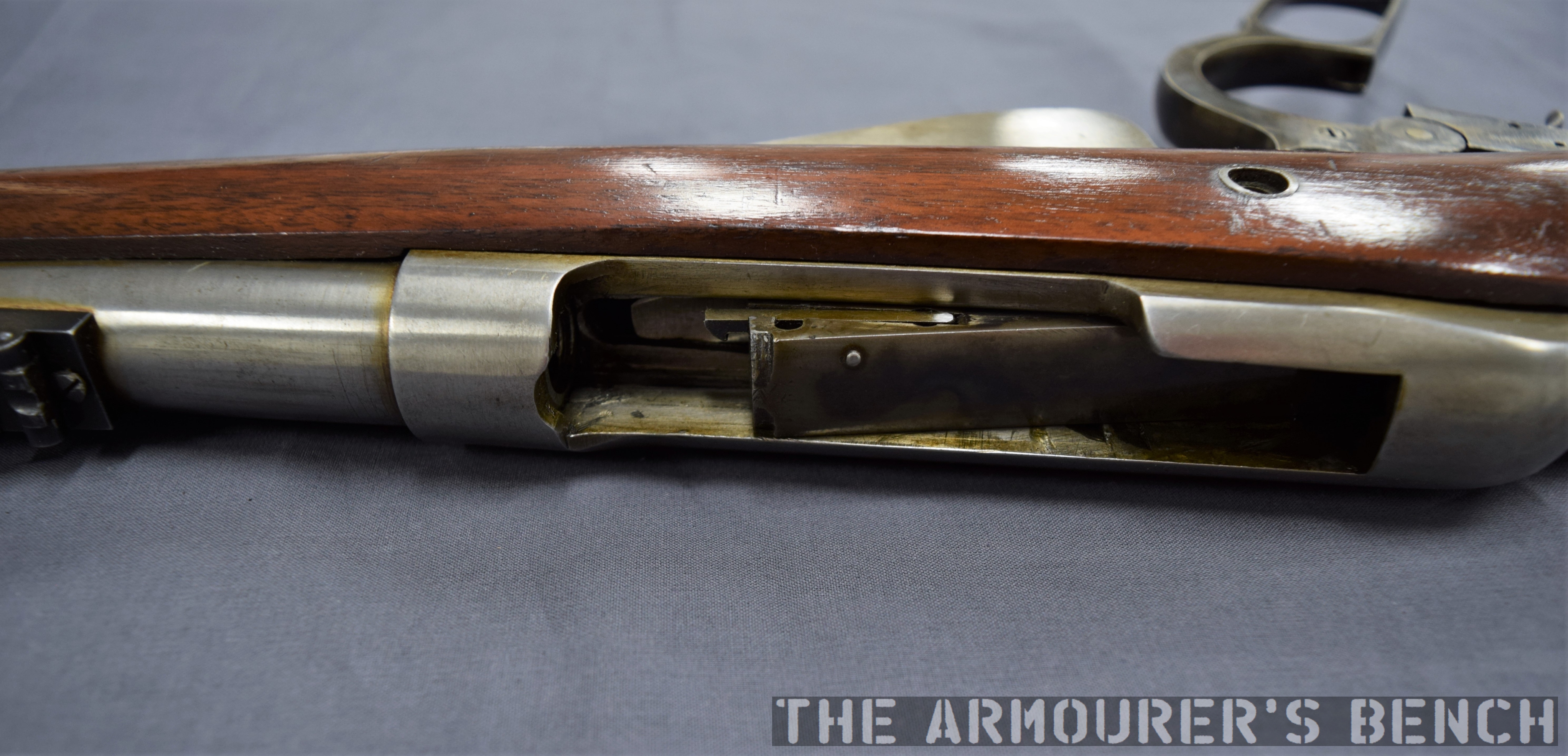
The prototype has a sliding safety bar that locks the lever and blocks the trigger. The trigger differs from the Model 1886 as it is integrated with the lever. In the photograph below we can see the locking block descended, with the lever forward, and the breech block to the rear with the action open. We can also see the striker assembly at the rear of the bolt. The striker cocks on closing when the lever is returned rearward.
The rifle with its action open, bolt o the rear and lever forward. Note the striker assembly at the rear of the bolt (Matthew Moss)
It’s quite an exposed action, with the entire top of the action open. With the action closed in the photograph below we can see the extractor running along the right side of the bolt.
A close up of the rifle’s receiver which is still ‘in the white’ (Matthew Moss)
It’s clear from the design of the magazine that Browning didn’t intend the rifle to be reloaded with stripper clips, although single loading of the rifle itself (not the magazine) would have been possible. When compared to other contemporary system this would have been somewhat of a disadvantage compared to Lee’s magazine’s later loading with chargers and stripper clips. However, from examination of Browning’s 1891 patent his intention becomes clear, the patent explains that he intended for the magazine itself to be replaced:
“One magazine may be readily removed from the gun and another introduced in its place, so that the person, using the arm may have at hand several magazines to be interchanged as the cartridges from one magazine are exhausted.”
This is a concept that wouldn’t be accepted by militaries for decades. Winchester purchased the rights to the design but this was one of many designs Browning sold the company which never saw production. The design and prototype are fascinating and represent one of Browning’s lesser-known concepts.
Left side profile of the rifle (Matthew Moss)
This rifle is a unique prototype and it was a true honour to examine it. It’s now on display at the newly refurbished Cody Firearms Museum, at the Buffalo Bill Centre of the West. The new museum is phenomenal and well worth a visit. Our thanks to the museum for allowing us to film items, like this one, from the museum’s collection.
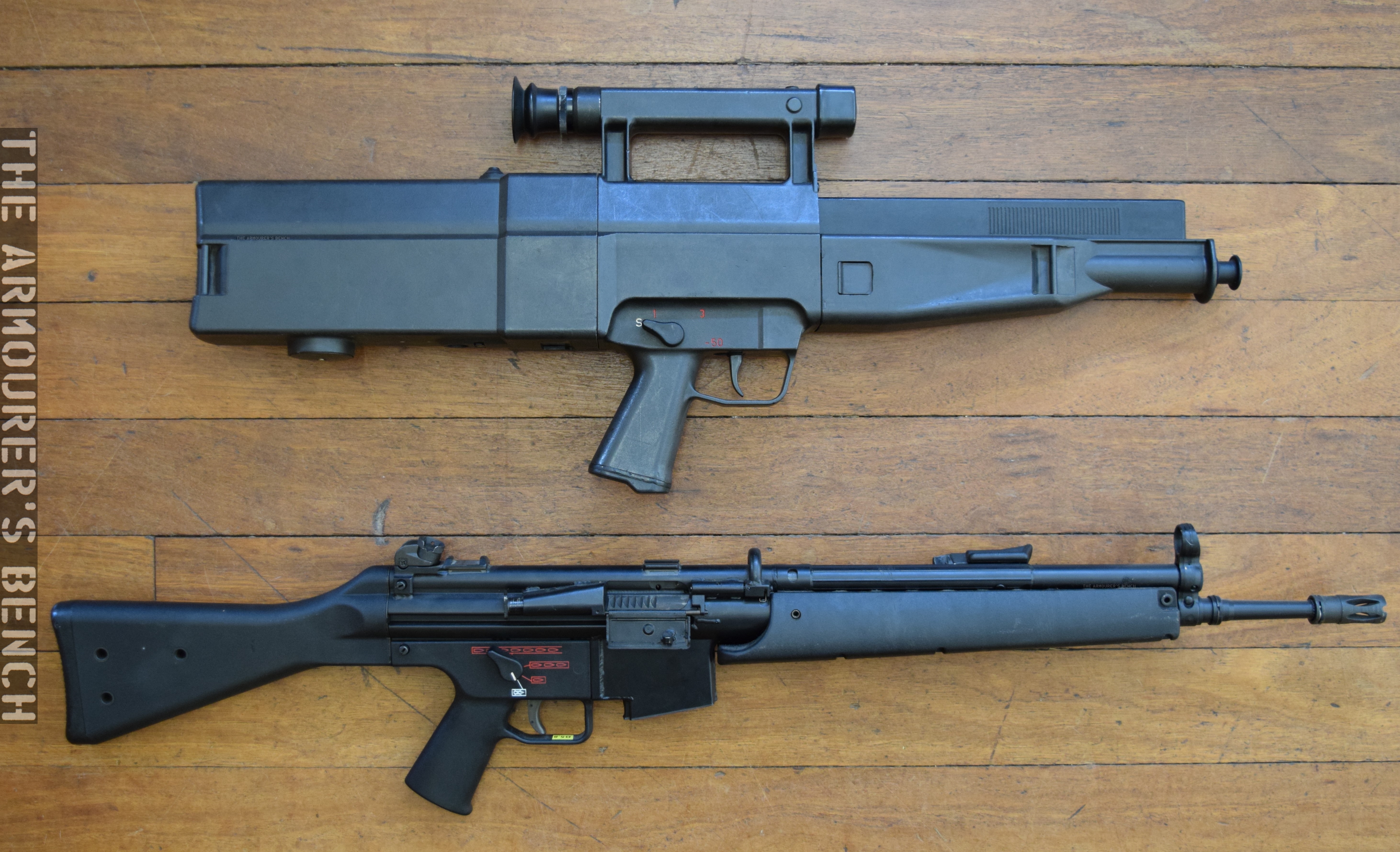
In 1981, Heckler & Koch introduced what would be their last infantry rifle that used their tried and tested roller-delayed blowback action, the HK G41. In October 1980, following NATO’s smalls arms and ammunition testing during the late 1970s, a meeting of NATO Armament Directors, agreed to standardise to the 5.56x45mm round favoured by the United States since the mid-1960s. Standardisation Agreement (STANAG) 4172 saw NATO standardise on the Belgian/FN SS109 ball round. At the same time Draft STANAG 4179 proposed adopting US 30-round M16 magazines as the standard 5.56 magazine pattern, while this proposal wasn’t ratified the M16’s magazine became the de facto standard.
At this time Heckler & Koch were engaged in a major engineering project to develop the G11 caseless ammunition-firing individual weapon. Their main offering for the 5.56x45mm rifle market at the time was the HK33, a rechambered version of the 7.62x51mm G3 developed by Tilo Moller, which was introduced in 1965. The HK33, however, used a proprietary HK magazine and was not compatible with the M16’s magazines. In 1977, as the NATO trials began and it became clear that 5.56x45mm would be adopted, HK began to develop what would become the G41. In 1979 with initial development completed HK submitted 18 G41s for testing with the West German Army. It wasn’t until 1981 that HK introduced the G41 onto the market.
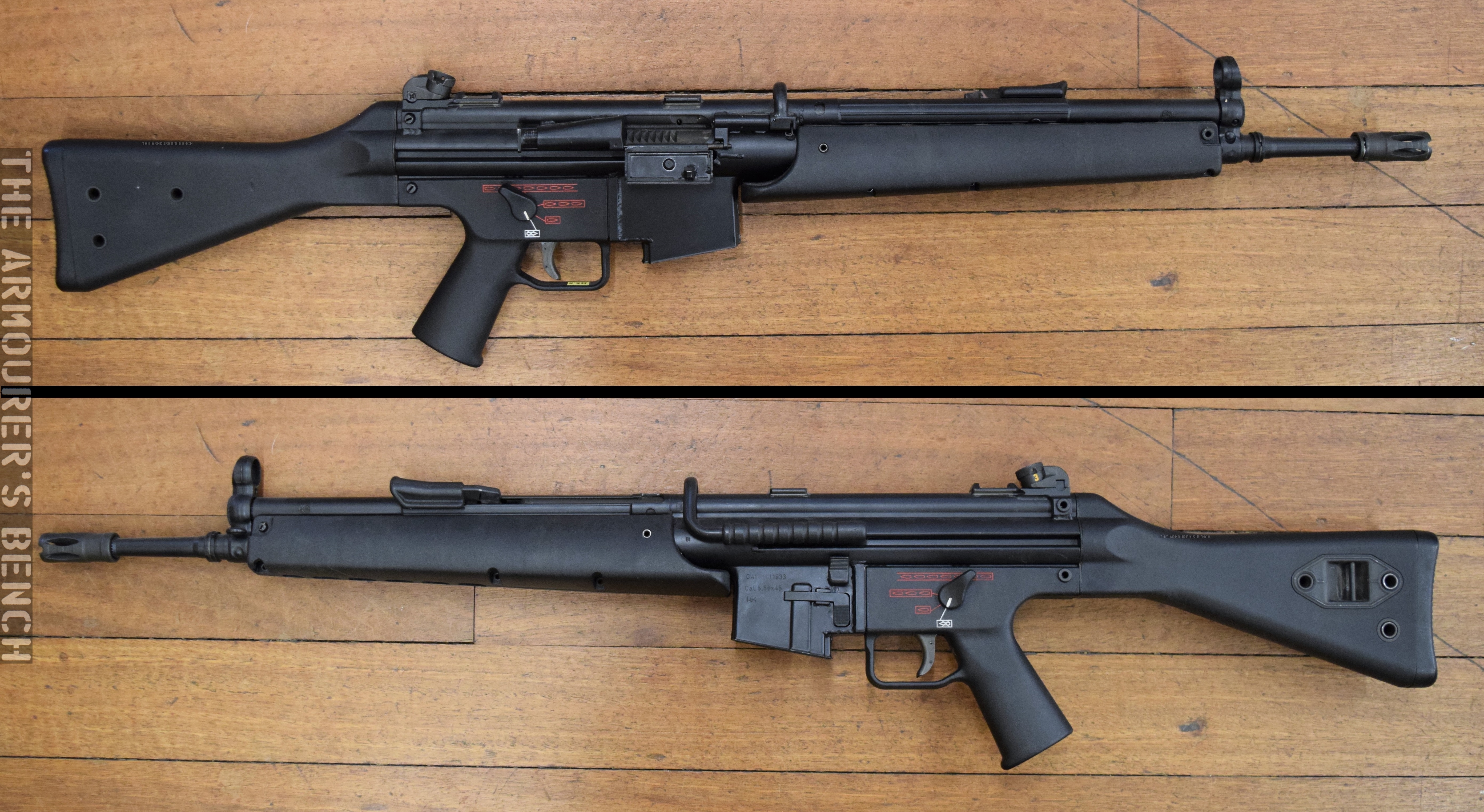
Left and right profile views of the G41 (Matthew Moss)
While continuing to use the same roller delayed blowback operating system as the G3, HK33 and MP5, the G41 embodied a number of improvements. While still using a stamped metal receiver it utilised 1mm thick high tensile steel rather than the 1.2mm thick steel used by the HK33. This helped to lighten the receiver. The new rifle also used a lighter bolt assembly, paired with a new recoil spring which comprised of five wound strands around a central coil, rather than a single coil, which had a longer stroke. This acted to lower the felt recoil. The G41, however, had a higher rate of fire at around 850 rounds per minute compared to the 750 rounds per minute of the HK33. Some of the G41’s bolt geometries were reworked and a new extractor was added.
The G41’s lower receiver was redesigned to allow the rifle to feed from STANAG magazines rather than HK’s earlier proprietary magazines. The cocking lever and forward assist were taken from the HK21A1 (XM262) general purpose machine gun, developed for the US SAW trials.
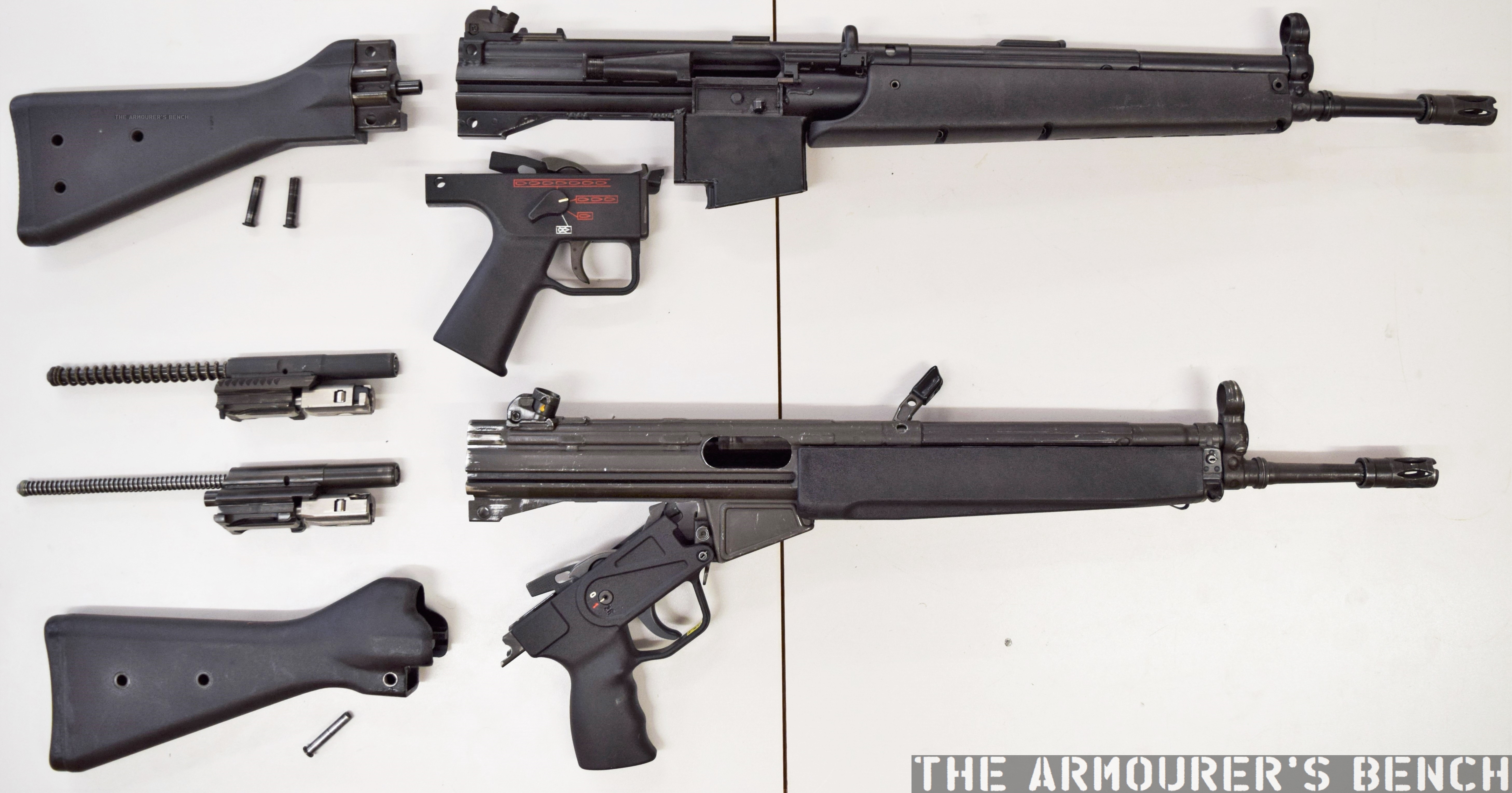
HK G41 (top) and HK33 (bottom) field stripped (Matthew Moss)
It also had a new more triangular polymer foregrip and added a plastic dust cover to the ejection port, a NATO pattern optics mount (meeting STANAG 2324) replaced HK’s claw-mount system, and a spring-loaded folding carrying handle near the centre of balance was added. Importantly it also added a last round hold open device and a bolt release catch, on the left side of the lower receiver.
The usual thumb serrations on the side of the bolt, for pushing the bolt home, were replaced by a prominent forward assist, similar to that found on the M16A1 and other HK weapons such as the HK21 light machine gun and the PSG-1 sniper rifle. HK sales literature described it as a ‘low noise’ forward assist and the manual describes the “quiet cocking of the weapon” – essentially riding the cocking handle back into battery and then pushing the forward assist to lock the action, the system is not as ‘low noise’ as advertised.
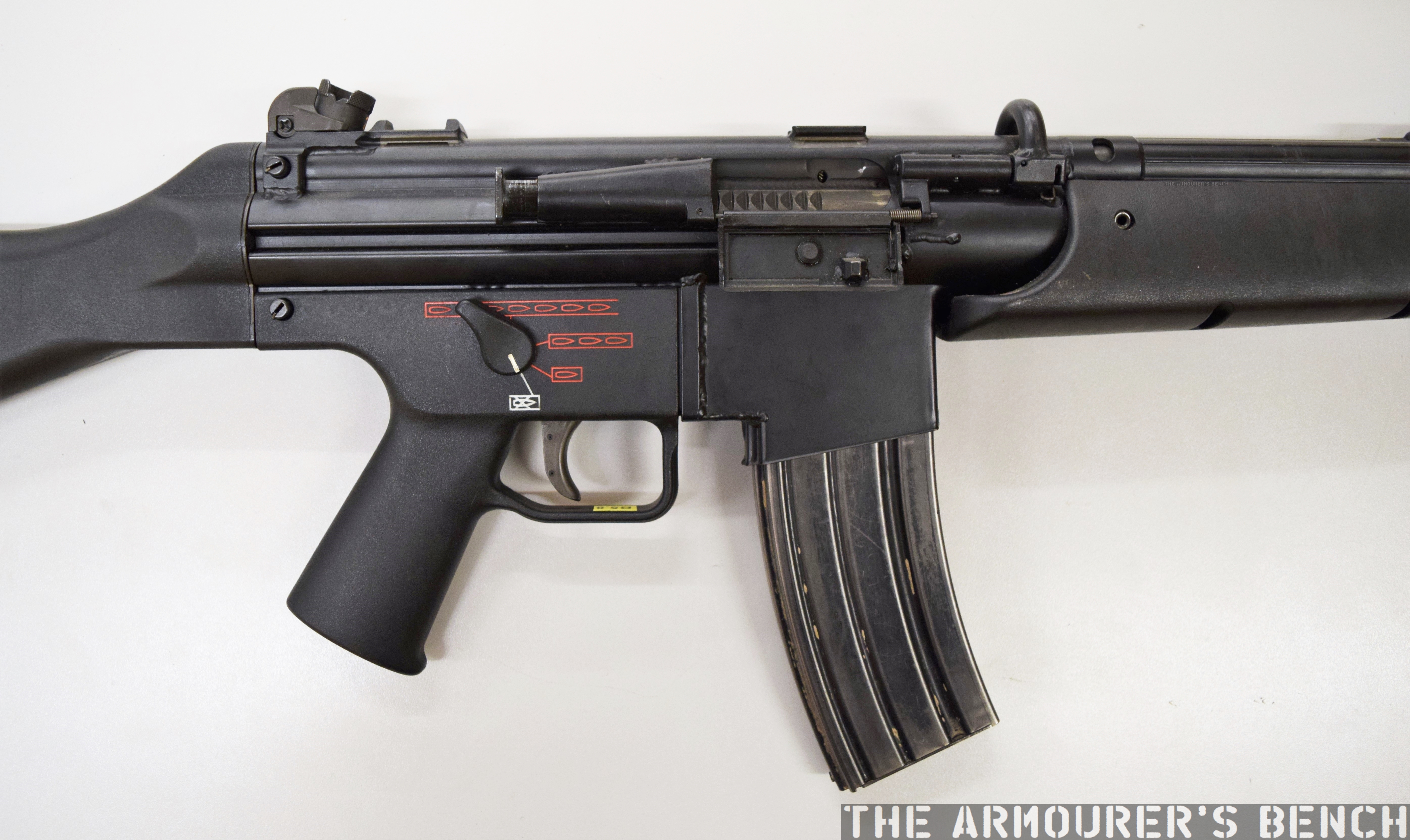
Right side of the G41, note the addition of a forward assist and dust cover (Matthew Moss)
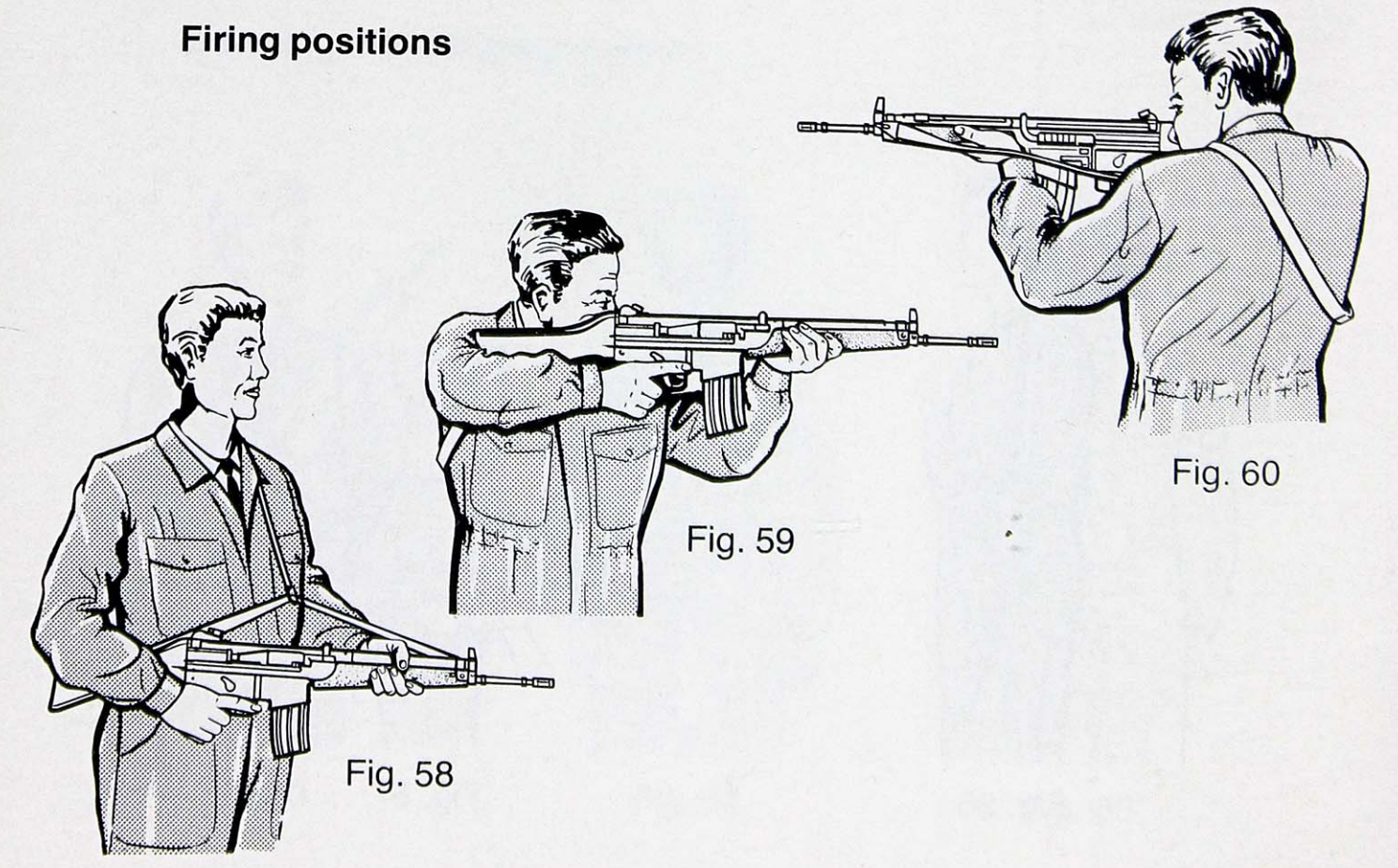
Another important feature of the rifle was the inclusion of a three-round burst setting alongside semi and fully automatic. The G41 could mount a standard G3 bayonet, fit an M16 bipod and had a flash hider designed to enable it to fire NATO standard rifle grenades. The 40mm HK79 under barrel grenade launcher could also be mounted to all variants of the G41, simply swapping it out for the polymer forend. HK referred to this set up as the G41-TGS or ‘Tactical Group Support system’.
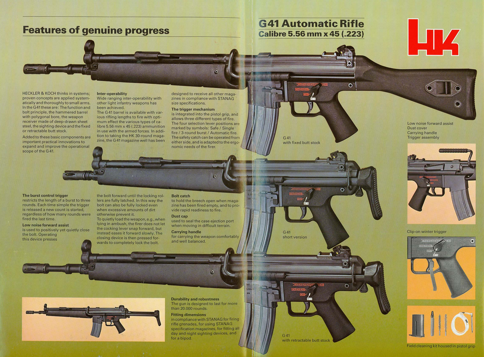
Spread from a 1985 HK promotional product brochure showing the various G41 configurations (HK)
The G41 came in a number of variants with designations A1 to A3. The base rifle had a fixed buttstock and its rifling had 1 turn in 7 inches with a right-hand twist, in a 18.9 inch barrel. The A1 had a 1 in 12” twist barrel and fixed buttstock. The A2 had a collapsing, single position stock and 1 in 7” inch twist rifling, while the A3 had 1 in 12” inch twist rifling. The 1 in 7” rifling was optimised for the new SS109, while the 1 in 12” optimised for the US M193 round. There was also a shortened G41K model which had a collapsing stock and a 15 inch barrel available with both rifling types.
One of the main issues with the G41 was its weight. Despite efforts to lighten the sheet metal receiver, it weighed more than its predecessor the HK33. According to measurement data compiled by researcher Nathaniel F, unloaded the G41 weighs in at 4.31kgs or 9.5 lbs, this is a full pound heavier than the HK33. A contemporary M16A2 weighed 3.39kg or 7.5 lbs while the Spanish CETME L, a similar stamped receiver rifle chambered in 5.56×45, weighed 3.72kg or 8.2 lbs. The rifle eventually adopted by the Bundeswehr, the HK G36, weighed 3.13kg or 7.3 lbs. The G41K with its collapsing steel stock wasn’t much lighter, weighing 4.3kg or 9.5 lbs, according to HK sales literature. Another potential issue may have been reliability with the move to the STANAG magazine rather than the optimised proprietary HK magazines may have introduced some issues.
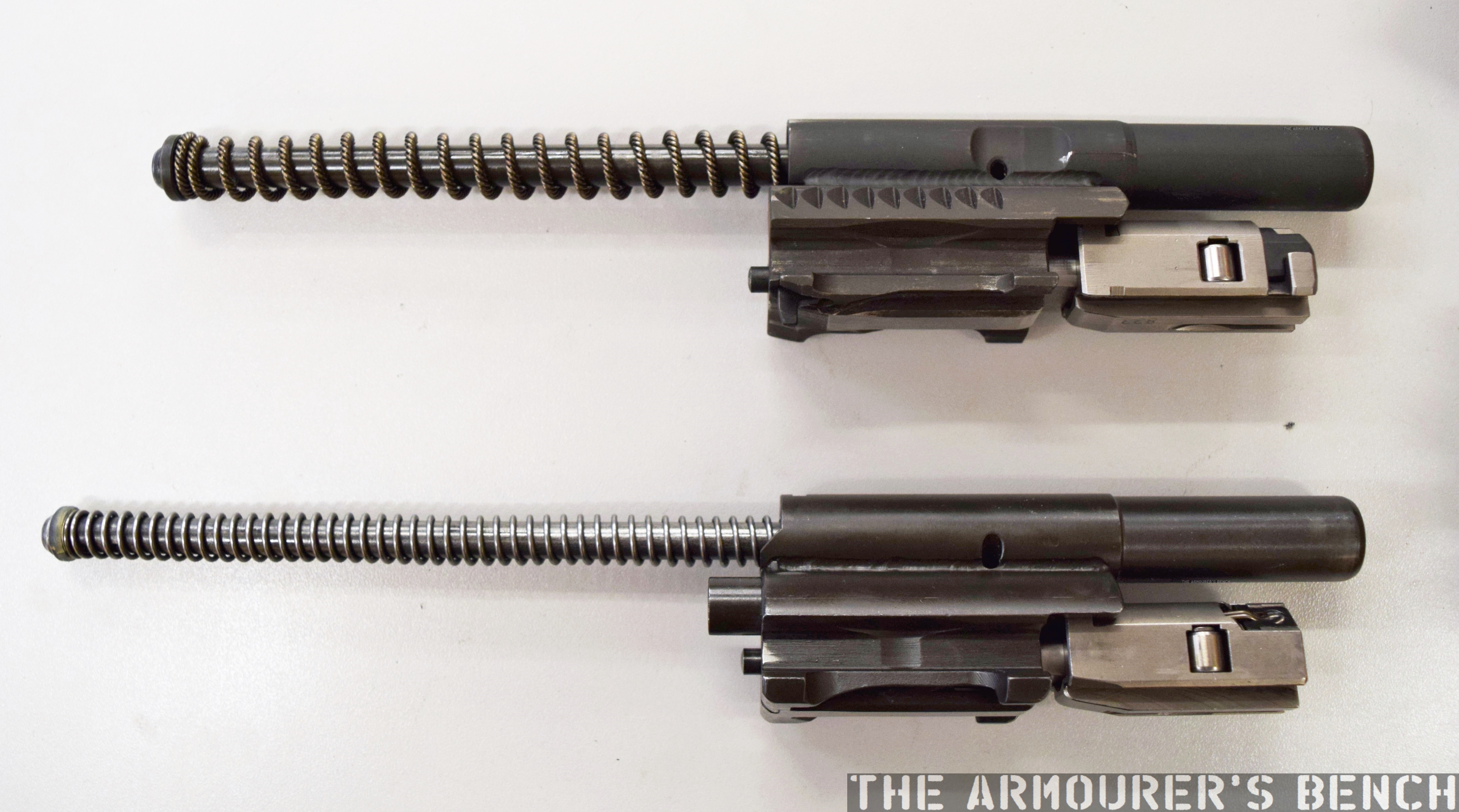
The bolts of the HK G41 (top) and HK33 (bottom), note the redesigned extractor, forward assist serrations on the bolt carrier and the G41’s thicker but shorter recoil spring (Matthew Moss)
Following NATO’s decision the early 1980s saw a large number of countries looking to replace their ageing 7.62x51mm battle rifles. Sweden began to look for a 5.56x45mm rifle to replace its licensed version of the G3, the Ak4, in the late 1970s. HK could initially only offer the HK33 but the G41, tested later, was also rejected by the Swedes in favour of FN’s FNC. Italy sought to replace the BM59 with a more modern rifle and HK entered into an agreement with Luigi Franchi which saw them offer both the original HK configuration and the develop their own, slightly modified version, the Franchi mod. 641, but the Beretta AR70/90 was selected. Similarly, in 1984 Spain decided to adopt the indigenously developed CETME L. In 1986 the HK G41 was also submitted to the Irish Army’s trials to replace the FN FAL, it was beaten by the Steyr AUG. Initially West Germany had hoped to procure up to 20,000 HK G11 rifles per year, with a total of 224,000 in service by 2003.
HK’s G11 and G41 (Matthew Moss)
The collapse of the Soviet Union and the subsequent reunification of Germany saw Federal budgets stretched and the G11 programme was subsequently abandoned entirely. The Bundeswehr still needed a suitable rifle to replace the G3 and in the 1990s sought a lighter weight rifle. HK felt their HK50 project, in development since the mid-1970s was a better bet than the heavier G41, and following Bundeswehr trials the G36 was subsequently adopted in 1997. Sadly, I have not been able to get a hold of any of the trials reports from the nations that tested the G41, so can not say with certainty why the countries mentioned above rejected HK’s rifle.
Graphic from HK’s manual for the G41 (HK)
From photographs of members of the Turkish Gendarmerie special operations group training at the Foça Commando School, dating from the early 2010s, it appears that Turkey either purchased a number of G41s or Turkey’s state-owned defence manufacturer, MKEK, produced an unknown number under license.At some point in the 1980s the British Army also tested a small number G41s with serial numbers #11131, #11832 and #11833 remaining in UK collections.
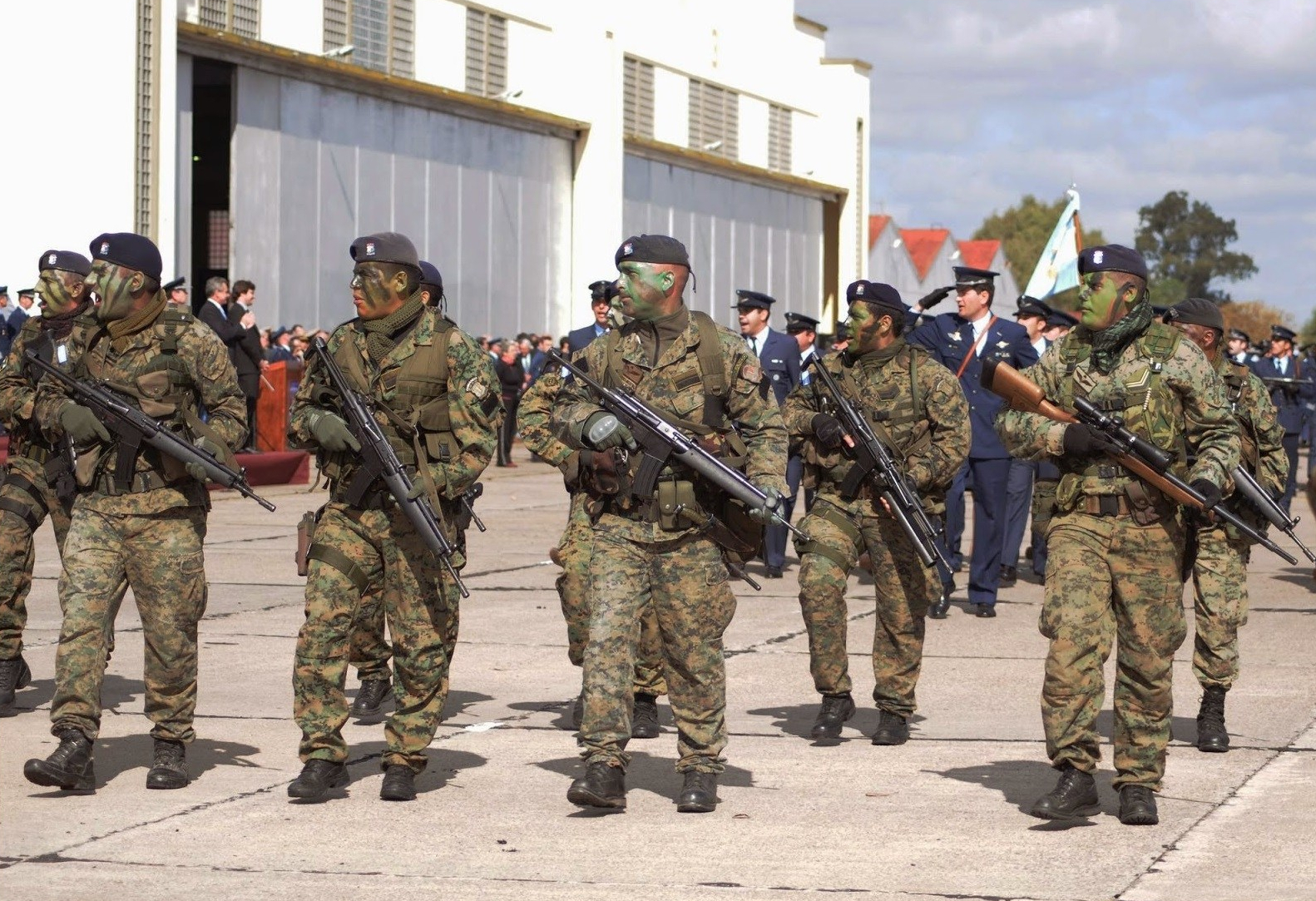
Denmark’s elite Jaegerkorpset and Froemandskorpset used the G41 for a time and Argentina’s special forces, including the Grupo de Operaciones Especiales, have also been photographed with both HK G41s and G41A2(collapsing stock) fitted with the TGS package comprising of the HK79 under barrel grenade launcher.
Argentina’s Grupo de Operaciones Especiales on parade with G41s and the G41-TGS, grenade launcher package (source)
The G41 represents the last evolution of HK’s infantry rifles using the roller delayed blowback action. It comes from a period when HK were developing what they hoped would be the next generation of small arms technology and with the collapse of the G11 programme and the lack of interest in the G41 the company faced financial uncertainty throughout the early 1990s. HK’s move away from the roller delayed blowback action to a more conventional gas operated rotating bolt system, combined with lightweight polymers, in the G36 proved to be more successful than the ill-fated G41.
If you enjoyed the video and this article please consider supporting our work here.


