Chinese Type 64 Suppressed Submachine Gun

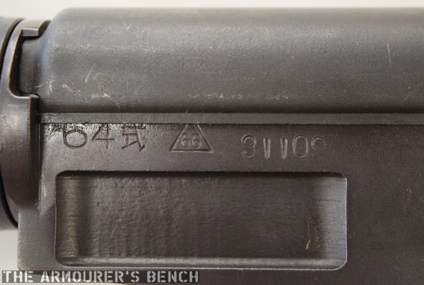
The Type 64 is an integrally suppressed submachine gun designed in China in the early 1960s, taking several design elements from other Combloc small arms. The guns were manufactured at one of China’s State Factories (with the factory’s ‘66’ in a triangle marking in the left side of the receiver – this indicates the factory number, although available sources differ on which it refers to, either 66, 626 or 366).

right_h13_chinese_smg
Right side of the Type 64, with stock folded (Matthew Moss)

Designed concurrently with the Type 64 suppressed pistol during the 1960s, the Type 64 SMG was developed for Communist China’s special forces for use in clandestine operations. Chambered in the standard 7.62×25 ComBloc pistol round, the Type 64 functioned best with Type 64 subsonic ammunition, a special subsonic spitzer projectile variation of the standard 7.62mm pistol round. It did not chamber the low power 7.65x17mm round used by the Type 64/67 pistols.

DSC_0070
A close up of the weapon’s markings, including the State Factory 66 stamping (Matthew Moss)

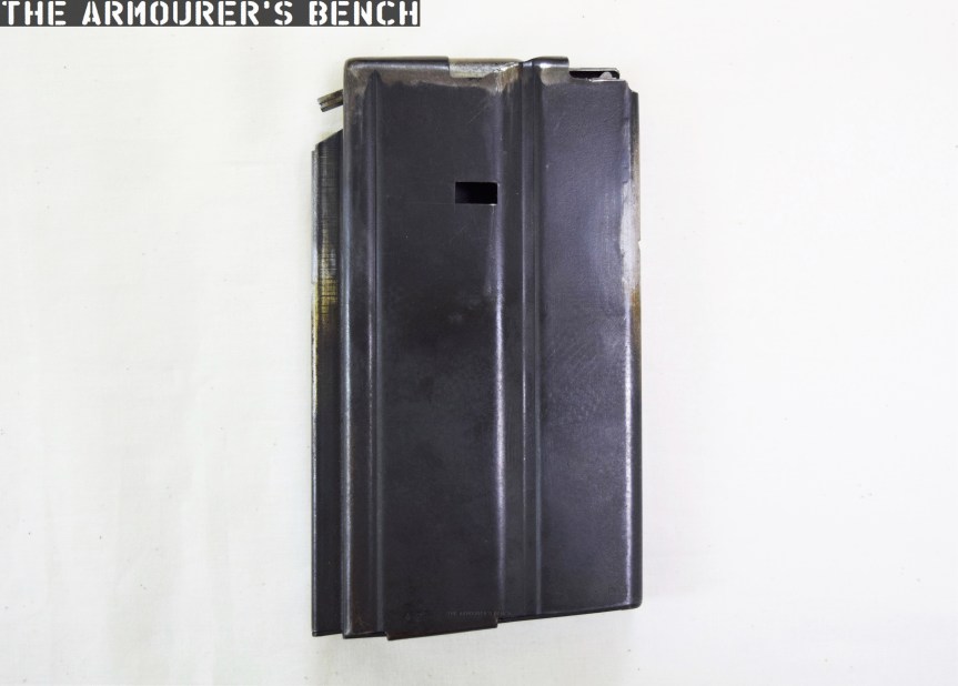
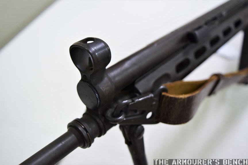
The Type 64 fed from 20 or 30 round double stack magazines which were reportedly developed from or at least influenced by the Soviet PPS-43’s double stack, double feed magazines. The weapon used a conventional blowback action and fired from an open bolt. Its maximum effective range was approximately 200 metres with two position flip up sights ranging out at 100 and 200 metres.

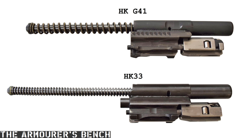
The Type 64 had a milled receiver with lightening cuts and weighed in at 7.6lb or 3.5kg unloaded. It took its bolt from the Russian PPS-43 submachine gun and a trigger group inspired by the ZB vz.26 light machine gun’s, which was well liked by the Chinese military.

DSC_0071
The suppressor housing is unscrewed at the trunnion with an interrupted thread (Matthew Moss)

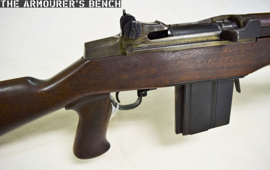
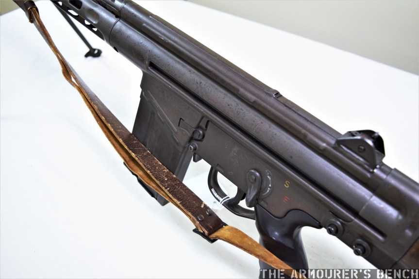
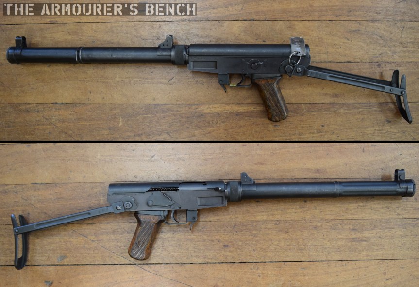
The Type 64 shared a number of external similarities with the standard Type 56 AK-clone including its pistol grip, safety lever and under-folding stock (which is similar but slightly different to the Type 56-I’s under-folding stock).

DSC_0067
The Type 64’s fire selector (Matthew Moss)

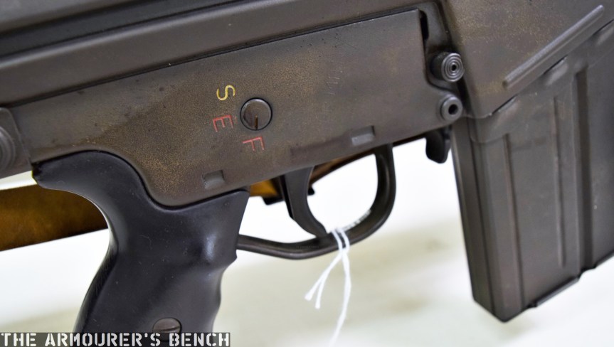
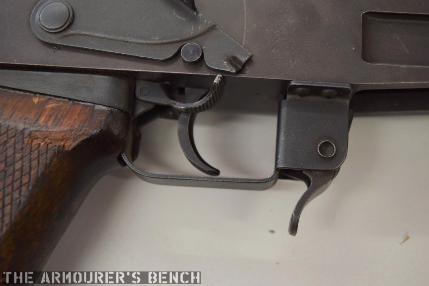
The weapon has a number different controls including a conventional AK-style safety-come-dust cover, on the right side of the receiver – which blocks the travel of the bolt. On the opposite side of the receiver it has a two-position fire selector for semi and full-auto – you can just about reach these when the stock is folded. The forward position is for semi and the rearward position is full-auto. Finally, the 64 also has an additional trigger block safety, taken from the SKS, which pivots forward to prevent the trigger from being pulled.

DSC_0054
A close up of the magazine release, trigger block safety and lever safety (Matthew Moss)

According to a report written in October 1971, by the Small Arms Systems Lab of the US Army Weapons Command Research and Engineering Directorate, the weapon has an extremely high rate of fire of over 1,300 rpm.

A cyclic rate that high was the result of a combination of back pressure from the suppressor, the ammunition used and its blowback action. The Type 64’s chamber was fluted with three longitudinal cuts to aid extraction at its high rates of fire. It should be noted, however, that the 1971 US army tests were carried out with standard velocity ammunition – rather than the specialised subsonic Type 64.

DSC_0251aaa
The Type 64 with stock deployed, left & right profiles (Matthew Moss)

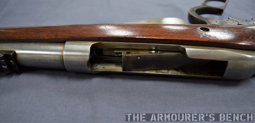
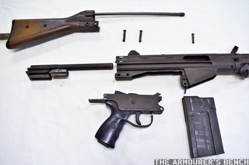
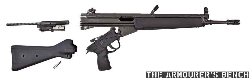
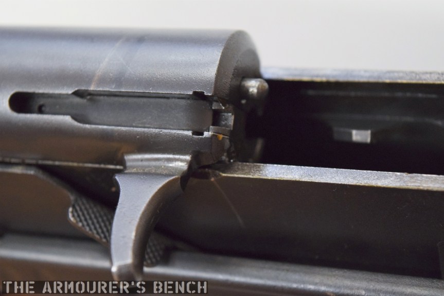
The top cover is removed by pushing in what at first appears to be a spring-loaded detent, but is actually the recoil spring guide rod. The front of the top cover is held in the receiver by a lip which fits into a slot just above the breech. The top cover itself is a thin piece of stamped sheet metal with the serial number stamped at the rear.

DSC_0090
With the receiver cover removed and the action cocked. The Type 64 fires from an open bolt. Note the buffer at the rear of the receiver (Matthew Moss)

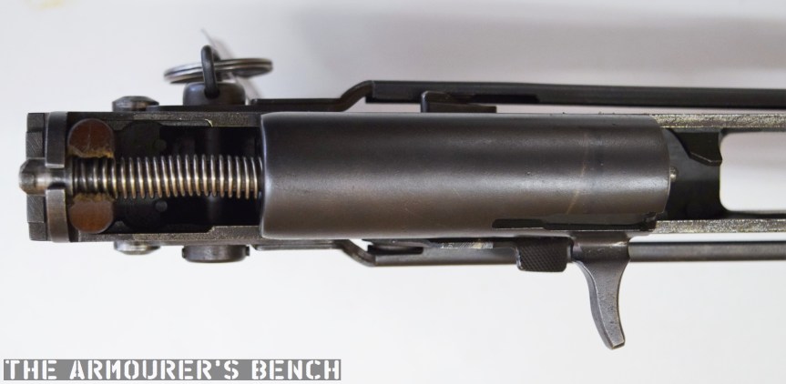
With the top cover removed we can see inside the action. The 64 has a single recoil spring held in place by a guide rod. At the rear of the receiver is a small plastic buffer, designed to both soak up some of the recoil energy and to help reduce action cycling noise. There is an ejector on the left side of the receiver and guide rails along which the bolt moves. To remove the bolt it is pulled fully to the rear and then tilt it upwards.

DSC_0094
A close up of the bolt face (Matthew Moss)

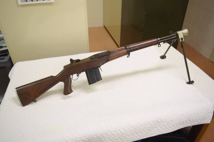
The Type 64 is a pretty compact weapon despite the length of its suppressor. It has an under-folding stock, with two spring-loaded buttons at the rear of the receiver which have to be pushed in to fold and unfold the stock. When folded the weapon is 25in (or 63.5cm) long, with the stock adding 8 inches when it is deployed. The weapon can be used with the stock folded, although some of its controls are partially obscured.

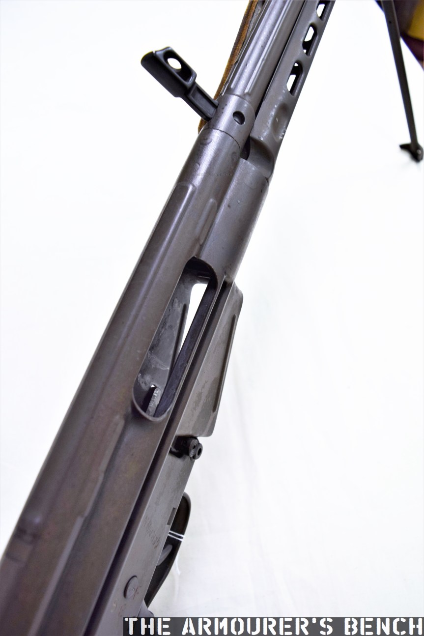
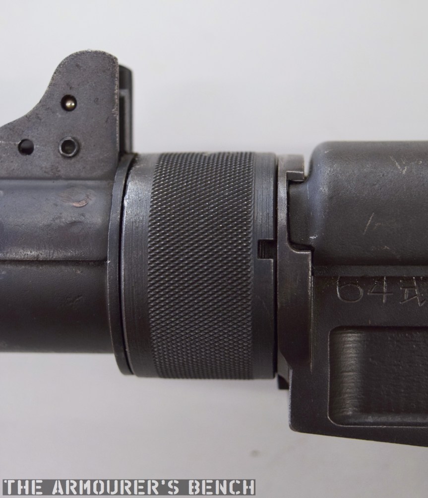
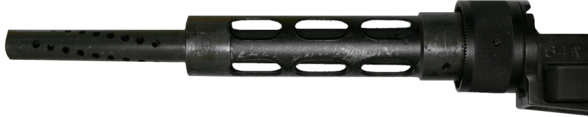
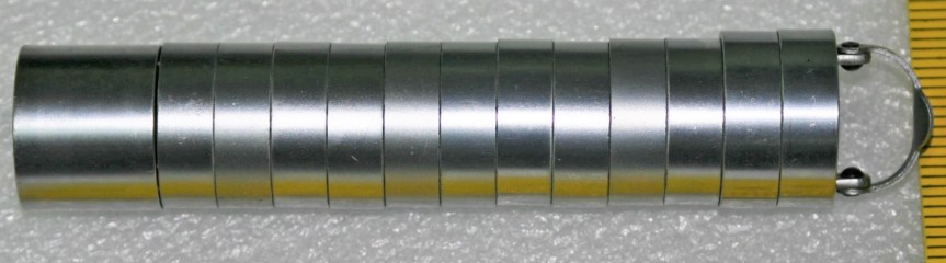
The suppressor is contained by a housing which attaches to the receiver by an interrupted thread. The Type 64’s barrel was ported with 36, 3mm vents at the muzzle-end while the suppressor has 12 metal dished baffles held captive on a pair of guide rods. The weapon’s sights are mounted on the suppressor housing which attaches to the receiver by an interrupted thread. Sadly, I didn’t have time to strip the suppressor itself but the photos below, from my friend Chuck over at Gunlab, show the Type 64’s ported barrel and baffles well.

type64silenced17
With the suppressor housing and baffle system removed. Note the series of holes in the barrel (GunLab)

The 1971 Small Arms Systems Lab report found that the audible report of the gun, was 150db at the rear of the receiver and 157db 12 feet down range, however, this is probably not the best indication of the Type 64’s capabilities as the report states that the gun was tested with Chinese Type 51 standard velocity 7.62x25mm ammunition. Ideally, the weapon would have been used with subsonic Type 64 ammo specially developed for China’s suppressed pistol-calibre weapons. Chinese sources reportedly put the weapons noise level at 84db when using subsonic ammunition. The US report did note that while its noise suppression wasn’t outstanding, it very effectively hid its muzzle flash.

type64silenced44a
The baffle system held together a pair of guide rods (GunLab)

It appears to have been primarily used by Chinese scouts and special forces and saw action during the 1979 Sino-Vietnamese War. In the late 80s the Chinese replaced the Type 64 with the suppressed version of the Type 85 submachine gun, also chambered in 7.62x25mm, which used the same magazines, the Type 85 had a tube metal and stamped receiver which was simpler to manufacture than the 64’s machined receiver. The Type 85 has subsequently been superseded by guns like the bullpup Type 05.

Special thanks to the collection that holds this weapon for allowing me to take a look at it. As always guys thank you for watching. If you enjoyed the video please share it with friends and help us


If you enjoyed the video and this article please consider supporting our work here. We have some great new perks available for Patreon Supporters.


Specifications:

Overall Length: 33.2in w/stock deployed
Barrel Length: 9.6in
Weight: 7.6 lbs
Action: Blowback, open bolt
Capacity: 20 or 30-round box magazines
Calibre: 7.62x25mm


Bibliography

Primary Sources:

‘Technical Notes: Chinese Communist 7.62mm Type 64, Silenced Submachine Gun’, US Army Weapons Command Research & Engineering Directorate Small Arms Systems Laboratory, J.J. Boccarossa, 27/09/1971

Secondary Sources:

Chinese Type 64 SMG, Small Arms Review, F. Iannamico (source)

Type 64 submachine gun (PR China), Modern Firearms, (source)

Chinese Type 64 suppressed SMG, ForgottenWeapons.com (source)

Winchester Select-Fire Garand Prototype


The Cody Firearms Museum, at the Buffalo Bill Centre of the West, holds a number of interesting select-fire M1 Garand rifles, adapted by Winchester during the 1940s. In this article we’re going to examine one of the prototypes, the rifle is believed to date to the late 1940s, and appears to be chambered in one of the earlier iterations of the T65 .30 Light Rifle round, which would eventually be adopted as 7.62x51mm.

Very little information is available about the rifle and little has been written about it previously. It is believed to have been developed by Winchester engineer Harry H. Sefried II with former Cody Firearms Museum curator Herbert Houze crediting Sefried with the rifle, which he described as adaptation of the M1 into a ‘squad automatic rifle’. After some archival research and combing Winchester’s patents from the period we can now attempt to shed light on a little more of the rifle’s history.

CFM photo
Winchester M1 Select-Fire prototype (Danny Michael/Cody Firearms Museum)

Externally, the rifle has a number of instantly recognisable distinctions from the standard M1 Garand. It has a reshaped stock with an added pistol grip, a proprietary box magazine and a combined bipod and conical flash hider. If we look closer we’ll notice that the stock has a swell just ahead of the breech, flaring out in an almost triangular bulge. These changes to the stock also distinguish this rifle from Winchester’s other select-fire M1 adaptations, which retain the standard Garand stock profile.

From the patents available combined with an examination of the rifle we can learn a lot. We cannot rely on patents to tell the whole story of the rifle, however, as many of the elements that make up the weapon appear to have gone unpatented. The substantial external and internal changes made to the rifle suggest that this was not an attempt to adapt the M1 with a minimal number of component parts changes but rather an effort to generally improve the rifle, making it conducive to fully automatic fire.

DSC_0231
Detail photo showing the rifle’s pistol grip, altered stock and magazine (Matthew Moss)

In summer 1944, Winchester’s CEO Edwin Pugsley directed Sefried to begin work on a select-fire conversion for the M1, to rival those being developed at Springfield Armory and Remington. Winchester’s select-fire Garand went though a number of iterations which resulted in two patents from Sefried. The first, filed in August 1944 (US #2479419), incorporated an elongated sear actuating lever and a selector on the lower, right side of the receiver. Winchester’s first attempts at a select-fire M1 conversion resulted in rifles with extremely high, uncontrollable rates of fire of over 900 rounds per minute. Sefried filed a second patent later in January 1948 (US #2464418) which used a catch to hook the sear. The rifle we are examining appears to have yet another select-fire system, one for which I have so far been unable to find a corresponding patent for. Winchester’s work on the select-fire adaptation came to a halt with the end of the war. It appears, however, that Winchester again began to work on adapting the M1 in the late 1940s, with Sefried again working on the project, filing his second select-fire mechanism patent in 1948 (US #2464418).

US2479419 sefrieds 1st patent
Sefried’s 1949 patent for another select-fire M1 conversion (US Patent Office)

The rifle’s receiver was originally a standard Winchester-made .30-06 M1 with a serial number of 1,627,456. This means its wartime production gun, dating from May 1945. It would appear that rather than the rifle being lifted from the rack finished, it seems that it was earmarked for prototype development because the receiver forging lacks the cuts/forgings needed for the en bloc clip release lever. This makes sense if it was known that the receiver was destined for use in a prototype which fed from a box magazine. However, the timeline of the rifle gets more complex when we consider that it was a late-war production rifle. There are a number of possibilities. The rifle may have been simply set aside for internal prototype work in May 1945 and not used until a T65 chambered rifle was developed later. Alternatively, it is possible that the rifle was converted during the initial attempts to create a select-fire M1 but was later rechambered from .30-06 to the new developmental T65 round.

This prototype’s trigger guard assembly, which also comprises the magazine well floorplate, is a self-contained assembly and does not interact with the weapon’s trigger mechanism or action. While Sefried had a patent for his own magazine system (US #2386722) this rifle uses a slightly different magazine release and floorplate, which is similar to one seen in Stefan Janson’s 1956 patent for a stripper clip-loading box magazine for the M1 (US #2894350). The magazine used in this prototype, however, is not the same as Janson’s. It has fixed feed-lips and a projection at its rear which appears to house an anti-tilt tab for the follower.

DSC_0234
The rifle’s magazine (Matthew Moss)

The rifle does not to appear to use the full-automatic system seen in either of Sefried’s patents.  Similarly, the safety selector is located on the left side of the receiver, forward, in line with the breech. It has two positions with an arc of about 90 degrees. This position does not match Sefried’s patents for select-fire conversion, however, it does match the position patented by David Marshall Williams but not Williams’ selector’s orientation of travel. I have been unable to find a patent which matches this rifle’s selector or method fully-automatic conversion.

DSC_0224
Left-side view of the rifle’s receiver showing the fire-selector (Matthew Moss)

The pistol grip is an interesting addition as neither of the other Winchester select-fire prototypes nor the original select-fire Springfield prototypes incorporated one. Visually it is very similar to that seen on the later Italian Beretta BM 59 Mark II.  In an effort to lighten the rifle the prototype also has an aluminium buttplate. One of ingenious internal changes is the milling of the bottom of the barrel flat, this not only has the effect of lightening the rifle but also allows a new, straight operating rod to travel rearwards under the barrel. How this impacted on the barrel’s harmonics is unclear. The rifle certainly feels lighter and handier (when unloaded) than you would expect, weight is estimated to be around 7 or 8 lbs.


The bipod, patented by Sefried in April 1945, (US #2420267) comprises a pair of tube steel legs, which have a set height, and a conical aluminium flash hider. The legs are spring-loaded and the entire assembly attaches via a latch which seats over the rifle’s bayonet lug. The bipod is the only element of this rifle that can be attributed to Sefried directly. And by the bipod’s very nature of attachment may simply have been attached later.

Sefried's April 1945 bipod and flash hider patent (US Patent Office)
Sefried’s 1947 patent for the bipod-flash hider (US Patent Office)

The best documentary source available for the prototype is the entry in the Winchester Factory Museum’s collection inventory offers some tantalising clues but no definitive answers:

#1504    U.S. Model M-1 rifle (Garand)
Cal. 30-06; experimental semi or full auto.
3rd type 20 shot box mag.
Special butt plate for shoulder rest
Bipod and aluminum flash hider attached
From H. Sefried 10-26-45

The suggestion that the rifle is chambered in .30-06 is seemingly an error given the internal changes made to the rifle. ‘3rd type’ suggests an iterative development of the rifle’s magazine while “special butt plate for shoulder rest” may allude to the aluminium butt plate but the prototype’s plate has nothing resembling a ‘shoulder rest’, instead it is a simple chequered aluminium plate about 5mm thick. While ‘From H. Sefried 10-26-45’ may refer to the whole rifle, I believe it more likely refers simply to his bipod.

DSC_0221
A close up of Sefried’s bipod-flash hider (Matthew Moss)

The prototype appears to be chambered in an iteration of the .30 Light Rifle round, which later became known as the T65. The rechambering was achieved by installing a metal block which shortened the magazine well. Unlike earlier Winchester select-fire conversions this rifle feeds from a proprietary magazine designed to feed the T65 round. This magazine does not appear to closely follow the pattern used by Winchester on several other designs during the period. The projection from the rear of the magazine slides along a channel cut in the metal magazine well block. It has font and rear locking shelves, with the front shelf acted on by the magazine release lever.

DSC_0229
A look at the rifle’s receiver and serial number markings from above (Matthew Moss)
S1230030_Moment
With the action open. Note the magazine insert at the rear of the magazine well (Matthew Moss)

Development of the .30 Light Rifle round, which would eventually become 7.62x51mm, began in 1944, with the round first being referred to as the T65 in 1946. It appears that the rifle is chambered in a version of the T65 cartridge, but which iteration exactly is unknown. However, its chambering does support the theory that the prototype may date from 1947-48. The T65 didn’t take on the now standard 7.62x51mm dimensions until 1949 in the form of the T65E3 round but without a chamber casting it is impossible to know the rifle’s exact chambering.

yn4QSZC
A photo representing the evolution of the .30 light rifle round (Courtesy of DrakeGmbH)

While Winchester continued to work on adapting the M1 Garand into a select-fire rifle none of their rifles were seriously considered by US Ordnance. At the same time John Garand was working on his own series of select-fire, magazine-fed prototypes (the T20 series) at Springfield while Remington had also been awarded a contract to develop a similar rifle, tested under the designation T22. These projects subsequently gave way to a number of other designs, all chambered in the T65 round, including the T25/47, T44 and T48. These were all tested before the Garand-influenced T44 was eventually selected in 1957, becoming the M14.

Addendum:

Harry Sefried II served in the US Army Air Corps during World War Two before joining Winchester as a firearms designer in 1944. In the 1950s he left Winchester to become Ruger’s chief engineer until he retired in 1979. He died in 2005, aged 84.


If you enjoyed the video and this article please consider supporting our work here. We have some great new perks available for Patreon Supporters.


Bibliography:

Patents:

‘Semiautomatic Firearm Convertible to Full Automatic’, H.H, Sefried, US Patent #2479419, 25/08/1944, (source)

‘Box Magazine Latch Mechanism for Repeating Firearms’, H.H, Sefried, US Patent #2386722, 29/09/1944, (source)

‘Support for Rifles and Other Shoulder Firearms’, H.H. Sefried, US Patent #2420267, 19/04/1945, (source)

‘Fire Control Mechanism for Automatic and Semiautomatic Firearms’, H.H, Sefried, US Patent #2464418, 02/01/1948, (source)

‘Strip Clip for Loading Box Magazines’, S.K. Janson, US Patent #2894350, 11/04/1956, (source)

Secondary Sources:

‘The Select-Fire M1 Garand’, F. Iannamico, Small Arms Review, (source)

Harry H. Sefried II Obituary, Hartford Courant, June 2005, (source)

‘Light Rifle, Part IV: The M1 Garand Learns To Rock And Roll’, TFB, Nathaniel F., (source)

Cartridge History for the Day – .30 Light Rifle, (source)

‘Winchester Proto-M14 Rifle’, Forgotten Weapons, (source)

Double Stack En Bloc Clips

Following on from our recent video on the John Browning prototype, which used en bloc clips, we have a video from our friend Jack Dutschke. Jack is an Australian cartridge collector, historian and author.

TAB Double-Stack En-Bloc clips_Moment
Some en bloc clips from Jack’s collection (Jack Dutschke)

In his first video with TAB Jack takes a look at en bloc clips, specifically double stack en blocs. Using examples from his impressive collection he discusses how en bloc clips work and takes us through their pros and cons.

TAB Double-Stack En-Bloc clips_Moment1
Garand & Pedersen en bloc clips (Jack Dutschke)

He examines the ubiquitous 8-round en bloc used by the M1 Garand as well as the much rarer 10-round clip for John Pedersen’s PA rifle which was chambered in his .276 round. Finally, Jack treats us to a look at a PTRS-41 anti-tank rifle en bloc clip which holds five massive rounds of 14.5x115mm.

TAB Double-Stack En-Bloc clips_Moment3
The big bastard – a Garand en bloc next to a PTRS-41 clip (Jack Dutschke)

Huge thanks to Jack for putting this video together for us, we’re really excited to have videos from him and we’re looking forward to more from him in the future! In the mean time you can find Jack’s project Cartridge Gram over on Instagram and on Facebook. He has a wealth of great photos and information on ammunition. 


If you enjoyed the video and this article please consider supporting our work here. We have some great new perks available for Patreon Supporters.

John Browning’s 1892 En Bloc Lever-Action Prototype

The 1890s were one of John Browning’s most prolific periods, during which he developed a host of firearms which would never actually see production. Here, we’re lucky enough to be able to examine one of those prototypes that were never produced. Dating from 1892, this rifle departs from Browning’s earlier lever-action rifle designs in a number of interesting ways. Perhaps the most interesting aspect of the design is its use of en bloc clips, instead of the tube magazine traditionally used by Winchester’s repeating rifles. John Browning, and his brother Matthew, filed the patent covering the design in June 1892.

DSC_0612a
Right side of the rifle, note its ‘musket’ configuration (Matthew Moss)

The rifle is in what is typically referred to at the time as a ‘Musket’ configuration, signifying that it is a military long-arm. It has a long 32.5 inch barrel, which is held in place by two barrel bands. Overall the rifle is around 50 inches in length and weighs just over 9lbs. The rifle is chambered in a .30 calibre cartridge, likely the then new .30-40 Krag round given its proposed market. It has a ladder-style rear sight with range graduations from 100 to 1,000 yards.

US486272-drawings-page-2
Browning’s patent drawing showing the rifle’s action (US Patent Office)

Okay, let’s take a closer look at the prototype. During the 1890s Browning experimented with a series of magazine systems including an en-bloc clip system. This rifle uses a 5-round magazine which is fed from an en-bloc clip. The idea of an en-bloc clip was relatively new with Ferdinand Mannlicher patenting the idea in the 1880s and using it in his Model 1886 and 1888 rifles. It is unclear if Browning was familiar with Mannlicher’s system but the two are very similar. If you’re unfamiliar with en bloc clips it means that the cartridges are loaded into the weapon in the clip rather than stripped from the clip.

DSC_0627
A look at the ejection port for the en-bloc clip (Matthew Moss)

Browning’s prototype holds five rounds in its clip, which from patent drawings we can see was not reversible. Sadly, we don’t have an example of Browning’s clip to examine but his 1892 patent (see above) gives us a good idea of what it would have looked like. It clearly has a cut at the top of the clip which appears to have been used to help guide the round up into the chamber.

Rounds were pushed up into the action by a follower arm which was actuated by a v-spring located at the front of the magazine housing. The bottom of the fixed magazine housing has a cut-out corresponding to the clip to allow it to fall or be pushed clear by a new clip once it was empty.

DSC_0615
The rifle’s lever fully-forward with its action open and striker cocked (Matthew Moss)

The rifle also departs from the traditional hammer system and uses a striker-fired action. From the patent drawings we can see how the rifle’s striker worked, with a coil spring extending into the stock and a sear holding the striker to the rear. The striker is made up of two pieces with the striker hitting a long firing pin inside the bolt.
The striker has, what the patent refers to as, a ‘thumb piece’ to enable re-cocking and to indicate if its cocked or not. The striker was cocked by the cycling of the lever and held in place by the trigger sear.

DSC_0625
A view inside the action with the bolt partially retracted before it moves down and back into the rifle’s wrist (Matthew Moss)

The lever was held in the close position, preventing out of battery discharges, by what Browning’s patent calls a downward-projecting dog, which projected through a small hole in the trigger assembly link and locked into a catch in the front of the lever loop.
The use of a striker, rather than an exposed hammer, allows the rifle bolt’s travel to be enclosed rather than have the bolt project out of the rear of the receiver, as in previous Winchester lever-actions, we can see that this rifle’s bolt slides back at an angle partially down into the wrist of the stock. This is arguably more ergonomic and potentially helps to prevent ingress of dirt.

The first half of the lever’s travel pulls the bolt to the rear, while the second part cocks the striker. An arm extending from the lever pushed the bolt rearward until the trigger sear was engaged. In order to give the lever enough throw to open the action far enough to allow a round to be loaded the trigger mechanism has to be pivoted out of the action, much like the earlier Winchester 1886.
The bolt has a pair of trunnions which project from the sides of the bolt, these run inside longitudinal grooves either side of the receiver, while the rear of the bolt is free to angle up and down as it cycles. The action is locked by the rear of the bolt secured against the rear of the receiver, rather than with a rising locking bolt.

DSC_0614a
Left side of the rifle (Matthew Moss)

During the period Browning was also working on other lever action and, even more unusual, so-called pull-apart actions as well as various magazine types including a revolving magazine, stripper-clip box magazines and of course as we’ve already seen a detachable box magazine-fed rifle. The 1890s were a truly prolific period for Browning.

The design was purchased by Winchester and the Brownings’ patent was granted in November 1892. The gun, like many of Browning’s other designs of the period, never saw production. Making this rifle a rare one-of-a-kind prototype. It’s an elegant design and the action is smooth. When Winchester did finally seek to produce a military lever-action they chose another of Browning’s designs which retained his traditional rear-locking bolt, which became the Model 1895.

This rifle is a unique prototype and it was an honour to examine it. It’s now on display at the newly refurbished Cody Firearms Museum at the Buffalo Bill Centre of the West. Our thanks to the museum for allowing us to film items, like this one, from the museum’s collection.


If you enjoyed the video and this article please consider supporting our work here. We have some great new perks available for Patreon Supporters.


Bibliography:

‘Breech-loading Firearm’, J. & M. Browning, US Patent #486272, 15/11/1892 (source)

John M Browning: American Gunmaker, J. Browning & C. Gentry (1964)

ArmaLite AR10 Sudanese Bayonet

We’re proud to present our very first bayonet-centric episode. Vic takes a look at a bayonet for a Sudanese contract AR-10 as part of his ongoing Surplus Zone series. While a rather rare bayonet this example has some interesting features.

In 1958 the Sudanese Military contracted with Samuel Cummings company Interarmco, to supply 2,508 AR-10 Battle Rifles. 2,500 standard rifles and 8 adapted to mount optical sights as sniper rifles.

One of the requirements for the Sudanese rifles were that they were to be able to mount bayonets, something the AR-10 did not have a capability to do in its then current form. This inability to mount a bayonet was overcome by a rather simple and ingenious addition to the rifle. A cast and machined sleeve was fitted over the barrel between front sight base/gas block and the flash hider. This was pinned to the barrel just forward of the front sight base/gas block. It had machined into the underside of the bayonet adaptor a longitudinal rail to which the bayonet could be attached. This is the same interface as seen on WWII German issued Kar98K rifles, the significance of which will become clear!

It is uncertain why Interarmco chose the design of bayonet which they did. It would have been quite an expensive and complex one to manufacture but it is obvious that it is based upon the late WWII SG-42 bayonet come utility/fighting knife. The Sudanese contract AR-10 bayonet has a more symmetrical blade than that of the SG-42 and has no ‘blood groove’ (properly known as a fuller) which hints at the fact that it is seen more of a utility knife than as a ‘cut and thrust’ fighting knife/bayonet.

Sudanese AR10 Bayonet.jpg
Sudanese contract AR-10 bayonet

It has been established that the SG-42 was manufactured by Waffenfabrik Carl Eickhorn in Solingen, Germany (determined by its cof marking / WaA19 inspection code), whereas the toolkit was made by Robert Klaas of Solingen (inspection code: ltk). Inside the bayonet’s grip are a number of tools which detach from the grip and can be used for rifle maintenance. The tools also include a bottle opener and a corkscrew. Inside the toolkit stored in the bayonet’s grip are a number of tools which detach from the grip and can be used for rifle maintenance. The tools also include a bottle opener and a corkscrew.

In regard to the AR-10 Sudanese bayonet, the Eickhorn company does not deny being the manufacturer of the Sudanese contract bayonet, they simply cannot confirm that they were the maker, since all relevant factory records have been lost!

In the Dutch AR-10 archives, Interarmco (i.e. Samuel Cummings) does not disclose the name of the manufacturer, but refers only (in the pertinent correspondence with A.I.) to “the Solingen manufacturer” of this knife-bayonet for the Sudanese contract.

Check out Vic’s earlier Surplus Zone videos here and his special series on the AR-10 here.


If you enjoyed the video and this article please consider supporting our work here. We have some great new perks available for Patreon Supporters.

Winchester Model 1905 .45ACP Conversion

During my recent visit to the Cody Firearms Museum I was lucky enough to examine a number of interesting firearms (more videos soon). In this video we take a look at a Winchester Model 1905 chambered in .45 ACP.

The Model 1905 was originally designed by Thomas Crossley Johnson, as a commercial rifle chambered in either .32 or .35 Winchester Self Loading. It was the second of a series of blowback operated rifles Johnson designed between 1903 and 1910.

DSC_0601
Right-side profile of the converted Model 1905 (Matthew Moss)

The origins of this gun, however, are less clear. It is part of the Cody Firearms Museum’s impressive collection and is believed to be a Winchester-made prototype. Dating the rifle is more difficult. It was originally believed to have been developed during the First World War but the Winchester Arms Collection’s records date the rifle to 1919. It has also been suggested that the conversion may have been developed by Winchester as an auxiliary arm for the US Army, as a replacement for the 1911 pistol for some troops – much along the lines of the later .30 carbine. There are no records, however, to suggest the .45 ACP Model 1905 was ever officially tested.

Herbert Houze, former curator of the Cody Firearms Museum, believed the conversion was actually developed after World War Two. No patents or Winchester documents are known to refer to it but Houze believed that one of Winchester’s engineers, Harry H. Sefried, developed the conversion as a side project with a potential aim to interest law enforcement agencies in a carbine chambered in the readily available .45 ACP round.

DSC_0599
The carbine with the 1911 magazine removed and the bolt back (Matthew Moss)

Taking a stock rifle a number of changes were made, the rifle was re-barrelled and rechambered for the .451-inch .45 ACP round and the bolt face was modified slightly. The 1905 originally fed from straight 5 or 10-round box magazines. In order to feed from a Colt 1911 magazine a new magazine housing was added. The curved front of the trigger guard has been machined back and is now flush with the rear of the conversion housing which appears to be integral to the lower receiver’s frame. On close inspection we can clearly see that parts have been brass brazed together around the original magazine release and inside the magazine well.

DSC_0603
With the 1905’s upper receiver removed we can see how the 1911 magazine aligns with the bolt and breech (Matthew Moss)

The rounded magazine housing has a new magazine release positioned at the front of the magazine, as in the 1911 and allows the magazine to be inserted at an angle. The ejection port has also been altered with an additional cut-out being made at the top to aid ejection.

DSC_0604
With the rifle stripped down and the magazine removed we can see the conversion magazine housing, note what appears to be brass brazing (Matthew Moss)

Take down remains the same, with the upper and lower separating once the take down screw at the rear of the receiver is loosened. The conversion appears to be well thought out and the finish and care taken would indicate this was rifle wasn’t a rough proof of concept prototype. Sadly, there is no information on how the conversion performed.

DSC_0599 - Copy (2)
A close up of the rifle’s receiver and Colt 1911 magazine (Matthew Moss)

Regardless of the origins of the conversion Winchester never offered the chambering commercially and this prototype is the only example known to exist. Today, it is held by the Cody Firearms Museum at the Buffalo Bill Centre of the West in Wyoming. The museum has just undergone a major renovation and is well worth visiting. Our special thanks to the CFM for letting us examine this rare rifle.

Herbert Houze, the former Curator of the Cody Firearms Museum who is mentioned in this article and video, recently passed away – this video is dedicated to his memory.


If you enjoyed the video and this article please consider supporting our work here. We have some great new perks available for Patreon Supporters.


Bibliography:

‘Winchester Center Fire Automatic Rifles’ ARMAX, The Journal of the Cody Firearms Museum (Vol. III, No. 1, 1990), K.F. Schreier Jr.

My thanks to Danny Michael, the CFM’s assistant curator, for additional information from Herb Houze


Browning Prototypes – Detachable Box Magazine Lever Action Rifle

The rifle we’re examining is one of dozens of designs sold by the Brownings to the Winchesters Repeating Arms Company during their long relationship. This design dates from the early 1890s and represents one of Browning’s numerous attempts to move away from the tube magazine-fed designs favoured by Winchester.

The prototype is based around the lever-actuated vertically sliding locking block patented by Browning in May 1884 and first used by Winchester in the Model 1886. The rifle itself is in the ‘military musket’ configuration with full-length handguards, military sights, a cleaning rod and able to mount a bayonet.

DSC_0590
Right side of the rifle (Matthew Moss)

The rifle is chambered in a .45 calibre cartridge, likely .45-70, and weighs just over 9lbs. Browning patented the design of the rifle and magazine in August 1891, with the patent being granted in December (US #465339). It is attributed to John Moses Browning and his younger brother Matthew S. Browning.

The most interesting feature of the rifle is its detachable box magazine. The magazine is held in place by a spring-loaded catch at the front of the magazine which locks against a tab in the magazine’s wall.

DSC_0577
A close up of the magazine well, note the added metal lip of the front of the well, not a part of the receiver (Matthew Moss)

It differs from the box magazines previously developed by James Paris Lee, which Lee begun developing in the mid-1870s (see examples listed below). It’s a simple design with a follower powered by a coil spring. The prototype mag itself is made from pressed metal and is held together with some rough welds. Unlike the magazines we’re familiar with today, the top of the Browning’s magazine is almost entirely enclosed with only a small opening at the rear. The rounds would be loaded nose-first with their rims sliding into the channel at the rear of the magazine.

DSC_0580
Close up of the magazine removed from the rifle – right side (Matthew Moss)
DSC_0586
A view of the top of the magazine with the small opening and notch for the cartridge rime visible (Matthew Moss)

The single-stack magazine appears to hold around five rounds, with Browning’s patent supporting this. The position of the magazine, in front of the action – not below it, is a hint at how it worked. An almost fully enclosed magazine does have its advantages – it would have prevented dirt from entering the mag and it also overcame the need for feed lips which were susceptible to damage, one of the elements which took Lee some time to perfect.

DSC_0582
A close up of the front wall of the magazine, note the locking notch (Matthew Moss)

So How Did The Magazine Work?

There is a shoulder on the underside of the bolt which caught the rim of the cartridge which was protruding from the magazine. The bolt pulled the cartridge backwards, out of the magazine and onto a cartridge lifter. As the lever reached its full forward travel the lifter then elevated the round up into line with the breech. When the lever was cycled back again the round was pushed off the lifter and chambered, just as in a normal tube-fed Winchester. As the lever reached the end of its return travel the locking block rose to locked the action.

US465339-drawings-page-2
The Browning’s 1891 patent for the magazine, note ‘h‘ is the shoulder which pulled rounds out of the magazine (US Patent Office)

The prototype has a sliding safety bar that locks the lever and blocks the trigger. The trigger differs from the Model 1886 as it is integrated with the lever. In the photograph below we can see the locking block descended, with the lever forward, and the breech block to the rear with the action open. We can also see the striker assembly at the rear of the bolt. The striker cocks on closing when the lever is returned rearward.

DSC_0595
The rifle with its action open, bolt o the rear and lever forward. Note the striker assembly at the rear of the bolt (Matthew Moss)

It’s quite an exposed action, with the entire top of the action open. With the action closed in the photograph below we can see the extractor running along the right side of the bolt.

DSC_0572
A close up of the rifle’s receiver which is still ‘in the white’ (Matthew Moss)

It’s clear from the design of the magazine that Browning didn’t intend the rifle to be reloaded with stripper clips, although single loading of the rifle itself (not the magazine) would have been possible. When compared to other contemporary system this would have been somewhat of a disadvantage compared to Lee’s magazine’s later loading with chargers and stripper clips. However, from examination of Browning’s 1891 patent his intention becomes clear, the patent explains that he intended for the magazine itself to be replaced:

“One magazine may be readily removed from the gun and another introduced in its place, so that the person, using the arm may have at hand several magazines to be interchanged as the cartridges from one magazine are exhausted.”

This is a concept that wouldn’t be accepted by militaries for decades. Winchester purchased the rights to the design but this was one of many designs Browning sold the company which never saw production. The design and prototype are fascinating and represent one of Browning’s lesser-known concepts.

DSC_0591
Left side profile of the rifle (Matthew Moss)

This rifle is a unique prototype and it was a true honour to examine it. It’s now on display at the newly refurbished Cody Firearms Museum, at the Buffalo Bill Centre of the West. The new museum is phenomenal and well worth a visit. Our thanks to the museum for allowing us to film items, like this one, from the museum’s collection.

If you enjoyed the video and this article please consider supporting our work here. We have some great new perks available for Patreon Supporters.


Bibliography:

‘Magazine Gun’ J.M. & M.S. Browning, US Patent #465339, 15 Dec. 1891 (source)

John M Browning: American Gunmaker, J. Browning & C. Gentry (1964)

Some of James Paris Lee’s magazine patents, for comparison:

‘Improvement in Magazine Fire-arms’, J.P. Lee, US Patent #221328, 4 Nov. 1879 (source)

‘Magazine For Fire Arms’, J.P. Lee & L.P. Diss, US Patent #295563, 25 Mar. 1884 (source)

‘Magazine Fire Arm’, J.P. Lee, US Patent #383363, 22 May, 1888 (source)

‘Gun Magazine’, J.P. Lee, US Patent #627824, 27 Jun. 1899 (source)

Vickers Gun Disassembly

The Vickers Gun is an iconic weapon, developed from the Maxim and adopted by the British in 1912. It served for over 50 years in conflicts all around the world. In this video, we’re lucky enough to have Richard Fisher of the Vickers Machine Gun Collection and Research Association shows us how to disassemble a the gun and talk us through its internals.

Big thank you to Rich for taking the time to help with this video and provide the voice over explaining the process! We’ll have more videos on the Vickers Gun in the future! Check out Richard’s work over on the Vickers Machine Gun Collection and Research Association’s site here.

I’ll let Rich explain the disassembly process in real time in the video but here are a couple of photographs of the gun disassembled:

DSC_0371
The Vickers gun field stripped (Matthew Moss)

This is the gun in its fully field stripped condition, with lock still assembled, but with its fusee spring and cover off and its barrel and action removed. Just below the barrel is the feed block.

Here’s the Vickers Gun’s lock disassembled into its 14 component parts:

DSC_0363
The gun’s disassembled lock (Matthew Moss)

This photo gives us a good look inside the receiver with the barrel, action and side plates removed, The spade grip assembly simply folds down to allow the action and barrel to be slide out of the gun.

DSC_0366
Once the action and barrel is removed you can look straight through the receiver and down through the water jacket (Matthew Moss)

Finally, here’s the gun reassembled and ready for action.

DSC_0353
The gun fully reassembled (Matthew Moss)

Thanks again to Richard for his help with this video, it was great to collaborate and hopefully we’ll have more videos with Rich in the future.  Please check out the Vickers Machine Gun Collection & Research Association’s site to find out more about what they do. They have some wonderful resources, including a comprehensive collection of manuals, for not just the Vickers but also the wider British Army from the past 100 years. You can also order copies of the brilliant instructional posters which were featured in the video over on the the associations website too!

If you enjoyed the video and this article please consider supporting our work here. We have some great new perks available for Patreon Supporters.


Rheinmetall G3

We’re all familiar with the Heckler & Koch G3 and its roller-delayed blowback action. What is less well-known is that H&K were one of two companies originally contracted by the West German government to produce the Bundeswehr’s new service rifle. The other company was Rheinmetall and today we’re lucky enough to be taking a look at an example of an early production Rheinmetall G3.

Left side (courtesy of the Cody Firearms Museum)

The rifle which became the G3 was of course originally developed by German and Spanish engineers working at the Centro de Estudios Tecnicos de Materiales Especiales (CETME) and was intended to equip the Spanish armed forces. Initially, the West German Bundesgrenzschutz (border guards) were interested in purchasing a substantial number of the new CETME rifles, with an initial order for 5,000 agreed, however, in September 1955 the order was cancelled due to delays in production and the Bundesgrenzschutz subsequently ordered the FN FAL instead.

In November 1955, the Bundeswehr (West German military) was formed and began to search for a suitable new 7.62x51mm service rifle. Having observed the Bundesgrenzschutz’ testing the fledgling Bundeswehr took an interest in the CETEME rifle. 400 ‘STG CETME’ rifles were ordered for troop trials and these were assembled in Germany by Heckler & Koch. The rifles were delivered in late 1956, and comparative trials against the FAL began the following year.

2015-06-05 13.18.23
CETME Model A (Courtesy of P. Hokana)

The trials found the ‘STG CETME’ to be satisfactory in terms of features and design but lacking in durability. A number of small changes were requested including a flash hider suitable for launching rifle grenades, either a flip-up or dioptre rear sight instead of a traditional tangent style, a case deflector, a simpler more ergonomic pistol grip, a longer more ergonomic cocking handle, changes to the recoil spring guide and tweaks to the shape of the buttstock. Additional improvements such as a stronger bipod, lighter magazine, a last round hold open mechanism, overall lightening of the rifle, a lighter 20-round magazine and a proper handguard were also requested.

DSC_0039
Left-side of the G3’s receiver, note the partial reinforcing rib on the magazine housing (Matthew Moss)

FN were unwilling to grant Germany a manufacturing license and the $110 per rifle price for the FAL proved substantially higher than CETME’s production estimates (The ArmaLite AR-10, J. Putnam Evans (2016), p.204). With adoption looking likely, legal wrangling over patent ownership began between Mauser, Rheinmetall and Heckler & Koch. All claimed the ownership of the roller-delayed blowback principle used by the CETME rifle. Eventually, however, the West German government awarded Rheinmetall and H&K future production contracts for the new rifle with the government supporting H&K’s claims but the legal battles continued for almost a decade.

In the meantime, with production of the CETME rifle not yet initiated and in light of some durability/reliability issues suffered during the STG CETME’s troop trials, 100,000 ‘Series C’ FN FALs were ordered for the Bundeswehr in late 1956. In 1957 the Swiss SIG 510 (designated the G2) and the American ArmaLite AR-10 (designated the G4) were also evaluated. Once the modifications requested after the troops trials were completed by H&K, a run of twenty rifles was produced and tested again.

DSC_0047
A view inside the ejection port of the G3 with the charging handle locked back (Matthew Moss)

In 1959, the West German government finally adopted the CETME rifle, designating it the G3. The German federal government decided that they wished to purchase the worldwide manufacturing rights to the G3, which naturally the Spanish government was reluctant to agree to. An agreement was finally reached in January 1958 and the contract giving West Germany worldwide rights to the G3 was finalised on February 4th, 1959.

One issue was that in June 1957, CETME had agreed a licensing deal for manufacture and sale of the rifle with a with a Dutch company Nederlandsche Wapen en Munitiefabriek (NWM). In order to gain the manufacturing rights sold to NWM the German government awarded the Dutch company a lucrative contract producing 20mm ammunition (Full Circle, p.234).

DSC_0045
A close up of the trigger mechanism housing, note ‘Germany’ faintly scratched into the surface (Matthew Moss)

Interestingly, as the German government owned the manufacturing rights, H&K initially had to pay the government 4 Deutsche Marks per rifle, despite having been awarded the contract by the German government. In late January 1959, H&K were awarded the first substantial production contract, amounting to 150,000 rifles. Rheinmetall were subsequently awarded a similar contract (Full Circle, p.235).

According to R. Blake Stevens’ book on the roller-delayed blowback action, Full Circle, Rheinmetall produced 500,000 G3s during the 1960s, delivering 8,000 rifles per month (Full Circle, p.287). As H&K had been designated as the technical lead on the G3 project, Rheinmetall’s engineers made no attempts to develop modifications or improvements and even when H&K had switched to plastic furniture the Rheinmetall guns continued to use wood. Rheinmetall’s only other G3-related project was the RH4, a 7.62x39mm chambered, roller-locked but gas-operated rifle designed for export (Historical Firearms).

Bundeswehrsoldaten_während_eines_Manövers_(1960) - Copy
W. German Army Armoured Reconnaissance car, with MG3 team with No.2 armed with G3, c.1960 (US Army)

In addition to the G3, Rheinmetall were the sole manufacturer of the MG3 machine gun, the 7.62x51mm MG42. Blake Stevens explains that in 1969, when a new tender for MG3 production was due, that H&K moved to undercut Rheinmetall who had until now held the monopoly on MG3 production (Full Circle, p.292). As a result an agreement was reached where Rheinmetall retained their monopoly on MG3 production and H&K became sole manufacturer of the G3 for the West German military.

Examining An Early Production Rheinmetall G3

The G3 went through a large number of changes both before and after it went into service. The rifle we’re examining today is a good example of an early production rifle, as adopted in 1959. This rifle is lightly marked with ‘G3 [Rheinmetall’s ‘star-in-a-circle’ logo] followed by a serial number of 745 and below that it is date marked with the ‘3/60’, for March 1960.

DSC_0043
A close up of the G3’s front sight and sling attachment point (Matthew Moss)

Working our way from the muzzle back; the rifle has the early style of flash-hider/grenade launcher support which was introduced in 1957 and altered in early 1961, an enclosed front sight and a detachable bipod (which was not Bundeswehr general issue). It has a stamped metal handguard which was replaced by one with a wooden insert in 1961, before H&K introduced plastic furniture in 1964.

DSC_0065
The G3 field stripped (Matthew Moss)

The folding carrying handle seen on the troop trials rifles has been removed, the receiver is stepped for the attachment of a scope base and the magazine housing has a single strengthening rib, rather than the later ‘full-frame’ continuous rib. It has an S-E-F selector (S – Sicher/safe, E – Einzelfeuer/semi, F – Feuerstoß/auto) and black plastic pistol grip. Internally, the rifle has a captive mainspring. Unlike later G3’s the rifle has a 2-position folding L-shape rear aperture sight with apertures for 200 & 300 metres rather than the later dioptre sight adopted officially in mid-1960. The rifle has a wooden stock held with a stamped metal sling attachment and a plastic buttplate.

If you enjoyed the video and this article please consider supporting our work here. We have some great new perks available for Patreon Supporters.


Specifications:

Overall Length: 40 in /1.2m
Barrel Length: 17.7in / 45cm
Weight: 8.6lbs / 3.6kg
Action: Roller-delayed blowback
Capacity: 20-round box magazine
Calibre: 7.62x51mm


Bibliography:

HK G3 Operator’s Manual – early 1970s (source)

Full Circle: A Treatise on Roller Locking, R. Blake Stevens (2006)

The ArmaLite AR-10, J. Putnam Evans (2016)

The CETME Assault Rifle, Small Arms Review, J. Huon, (source)

Our special thanks to the Cody Firearms Museum, at the Buffalo Bill Center of the West, for their kind permission to film items from their collection and their assistance in filming and research.

Heckler & Koch HK33

Heckler & Koch’s first 5.56×45 rifle, the HK33, was introduced in the late 1960s as a response to the emergence of the new 5.56x45mm round and the introduction of the FN CAL. The HK33 is little more than a scaled down version of HK’s successful 7.62×51 G3. Developed by Tilo Möller, the HK33 used the same roller delayed blowback action and shares most of the G3’s features.

ccccccccccccccccccccc
Left & right views of the HK33 (Matthew Moss)

It has a stamped receiver and uses the same plastic furniture and pistol grip/trigger mechanism housing as the G3. The rifle is 39 inches or 92cm long and is by no means a light weapon, weighing around 4kg or 8.7 lbs. The HK33 feeds from 25, 30 or 40 round proprietary HK magazines.

The rifle came in main two main variants a full length version with a fixed stock, which could be fitted with a collapsing stock, and a shortened K-variant with a shorter barrel. The weapon came with either a safe, semi and full auto or safe, semi, 3-round burst fire control mechanism.

hk33 brochure 1
HK factory brochure showing the variants of the HK33 (Heckler & Koch)

The HK33 was not adopted by the West German Army, however, it did see extensive use with Germany’s federal state and police forces and the Bundeswehr special forces. While it wasn’t adopted at home it was a successful export weapon with dozens of countries purchasing and adopting the rifle. France tested the improved HK33F in the Army 1970s and although it performed well the FAMAS was adopted instead. A production license was sold to Thailand who adopted the HK33, purchasing 40,000 rifles and the license to manufacture 30,000 more. Thailand also developed their own unique bull pup version of the rifle, the Type 11.

right_disassemblied_h13_gewehr_41_hk_33a
HK33 field stripped (Matthew Moss)

Malaysia also purchased 55,000 HK33s and the Spanish Guardia Civil used them for a time. The manufacturing rights for the HK33 were also sold to Portugal for production at Fabrica Militar de Prata and to Turkey where it remains in production at MKEK.

action_h13_gewehr_41_hk_33labeled
A comparison of the HK33’s bolt with the later HK G41 (Matthew Moss)

HK produced the HK33 from 1968 through to the late 1980s. It also provided the basis for the HK53 5.56 ‘submachine gun’ which we have covered previously. It was also the basis of the less successful G41, which we’ve also covered in a full length episode, you can find this here. The similarities with the HK33 are easy to see but the G41 has a number of subtle changes.

If you enjoyed the video and this article please consider supporting our work here.


Specifications (from 1985 factory brochure):

Overall Length (with fixed stock): 36in /92cm
Barrel Length: 15.7in / 40cm
Weight: 8.7lbs / 4kg
Action: Roller-delayed blowback
Capacity: 25, 30 or 40-round box magazine
Calibre: 5.56x45mm


Bibliography:

Full Circle: A Treatise on Roller Locking, R. Blake Stevens (2006)

HK33 Factory Brochure, c.1966 (source)

HK33E Factory Brochure, c.1985 (source)