XF-87 Blackhawk

Development of the XF-87 began at Curtiss-Wright in 1946, it would eventually be intended to be an all-weather interceptor. The Blackhawk was developed from an earlier ground attack, tactical bomber design, the XA-43. The Blackhawk was a response to the initial specification for a jet-powered night fighter, capable of speeds up to 530 mph, issued by the US Army Air Force in August 1945.

A number of companies responded including Bell Aircraft, Consolidated-Vultee, Douglas Aircraft, Northrop, Goodyear and Curtiss-Wright. The US Army Air Force down-selected Northrop’s design – then known as the N-24 and the Curtiss-Wright design- known as the Model 29A.

Curtiss-Wright XF-87 (US Air Force)

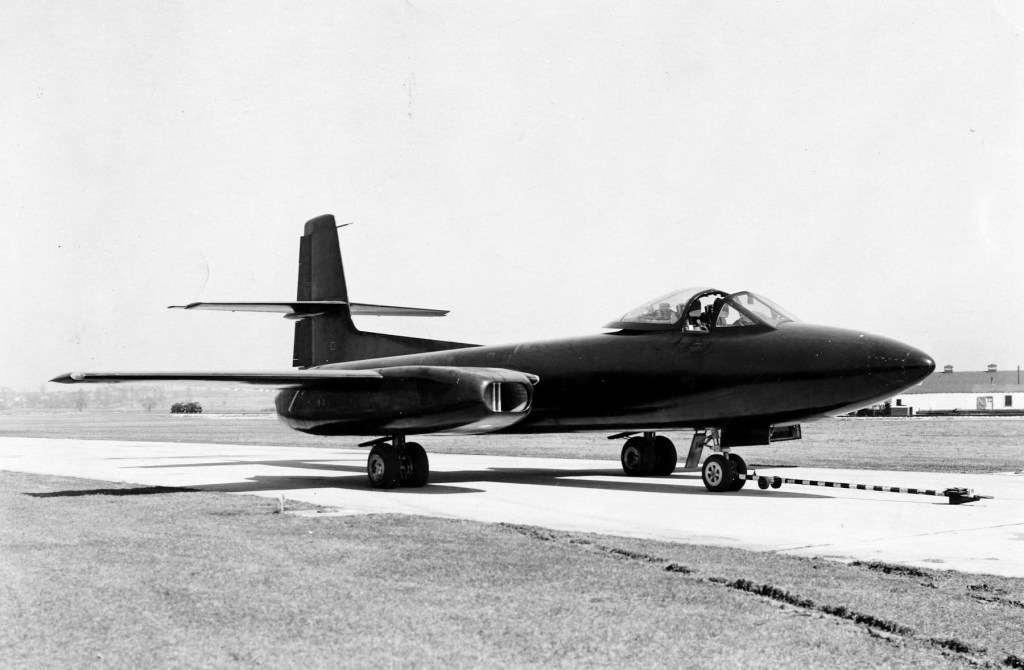
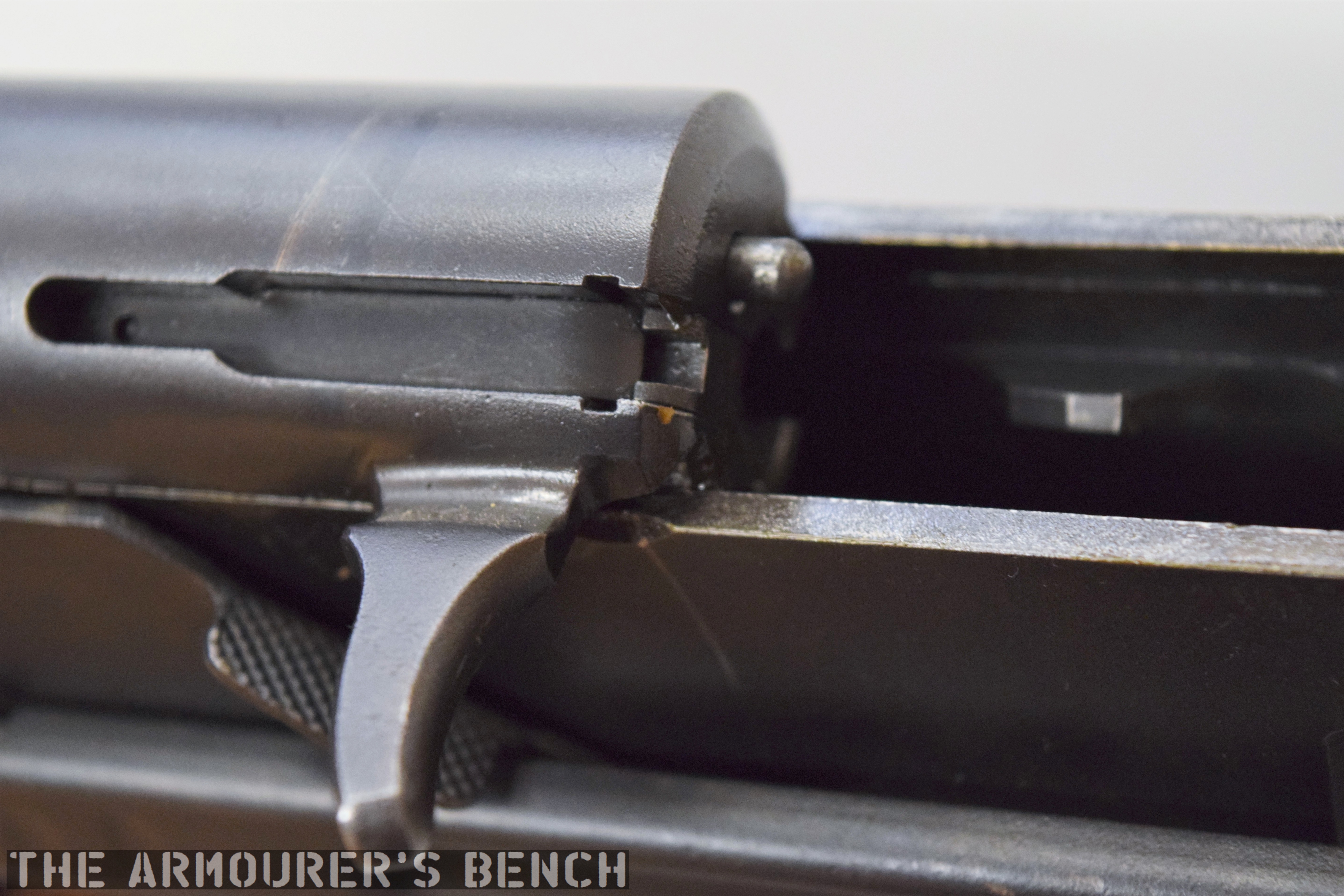
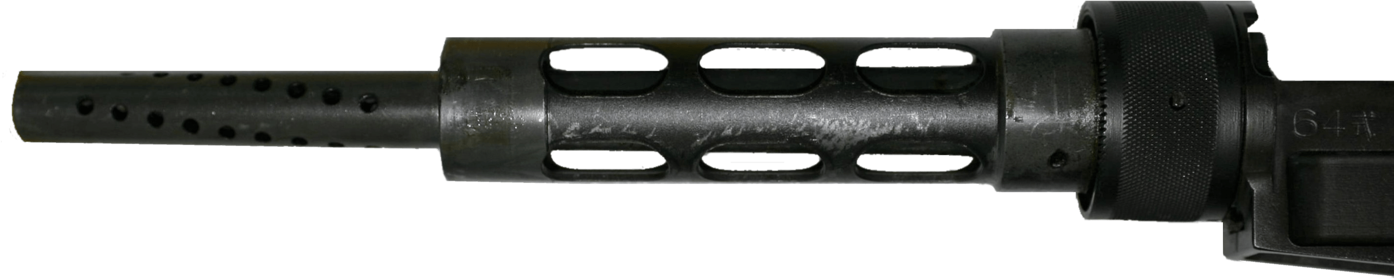
The XP-87 had a two-man crew seated side-by-side and was powered by two pairs of Westinghouse XJ34-WE-7 turbojet engines mounted on the wings. In comparison to the sleeker Northrop design, the Blackhawk was a slightly larger, bulkier and heavier aircraft with a straight wing profile. The XJ34-WE-7 turbojets only provided 12,000 lbf and Curtiss-Wright’s test pilot B. Lee Miller described performance in initial tests as sluggish. The Blackhawk’s armament was to consist of four 20mm cannons mounted in a nose turret.

The US Army Air Force designated the Curtiss-Wright jet the XP-87, while Northrop’s N-24 became the XP-89 and full-scale models of both were ordered.

The Curtis XP-87 (Curtiss-Wright, courtesy of Mark Lane)

In June 1948 the newly formed US Air Force re-designated fighters from P to F and the XP-87 became the XF-87 when prototypes were ordered. The XF-87 made its first flight in March 1948. During subsequent flight evaluations in October 1948, the Northrop XF-89 was found to be faster than the XF-87 and the US Navy’s XF3D (Douglas F3D Skyknight). While the Blackhawk was a capable and generally satisfactory aircraft it was deemed to be underpowered. It also reportedly suffered from buffeting at relatively slow speeds.

Walter Tydon’s patent for the Blackhawk’s landing gear (US Patent Office)

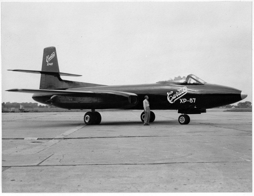
Evaluators disliked the Northrop and reportedly favoured the XF-87, however, one evaluating pilot likened its handling to a medium Bomber. An improved faster and more powerful Blackhawk was planned with J47 engines from General Electric. The fate of a second prototype is unclear and sources conflict. Most sources state that the XF-87 never had its armament fitted, however, photographic evidence clearly shows an aircraft, not with a turret, but with four nose mounted guns. This aircraft may be one of the airworthy prototypes or it could be a full-scale mock up built to show the USAAF during the selection process.

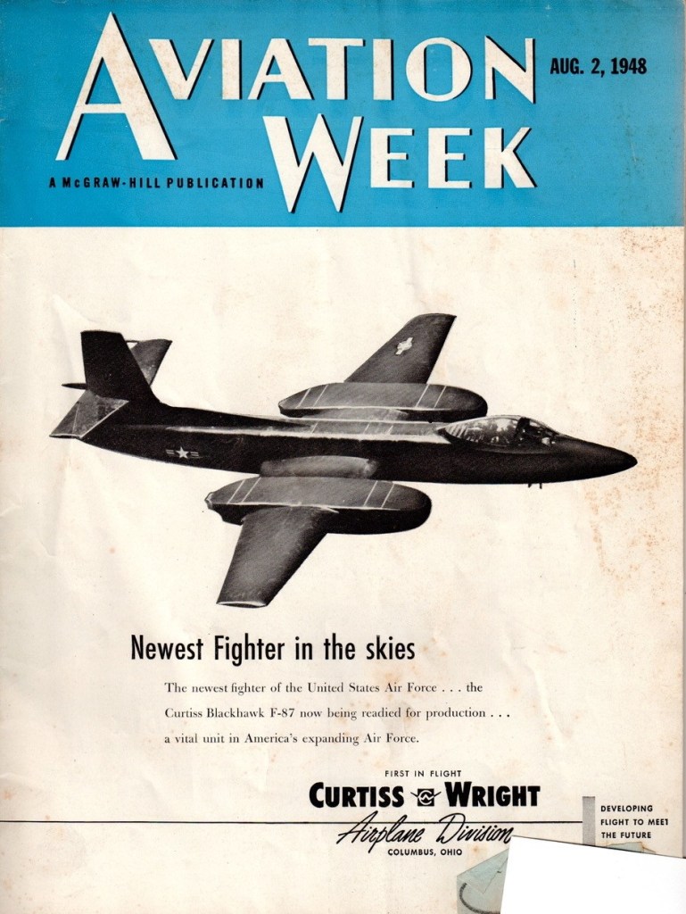
Despite the trials favouring the XF-89, the USAF initially ordered 57 F-87A fighters and 30 RF-87A reconnaissance aircraft from Curtiss-Wright in June 1948. Curtis-Wright and the USAF began a publicity campaign to unveil the new fighter, even appearing on the cover of an August edition of Aviation Week and in numerous other aviation publications, but the orders were abruptly cancelled in October 1948 and the USAF moved forward the development of the Northrop XF-89 instead. Check out our video on the F-89 Scorpion linked above.

The ‘F-87’ Blackhawk on the cover of Aviation Week (courtesy of Mark Lane)

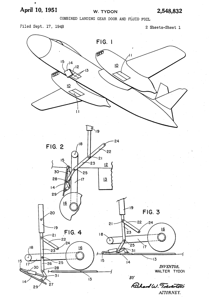
The reason for this reversal of the decision is unclear. Only minor faults had been identified during testing and the more powerful J47 engines would have greatly increased the Blackhawk’s speed. The official reason for the cancellation was reportedly a disagreement on the price of a redesigned wing profile. According to his memoir, Walter Tydon, Curtiss-Wright’s chief engineer at the time, believed that some bad blood between Curtiss-Wright’s management and the then-President Harry S. Truman may have led the F-87 contract to be cancelled. Truman was Senator for Missouri from 1935 to 1945 and during that time Tydon believed he had come into conflict with the Curtiss-Wright’s management, perhaps regarding the company’s factory in St. Louis. Without substantial archival research it is difficult to verify either the official reason or Tydon’s theory.

Another potential reason for the cancellation was raised during the Congressional Hearings regarding the B-36 Program, Congressman Charles B. Deane noted that both Curtiss-Wright and Northrop had been informed that “unless they agreed to merge with Consolidated Vultee, business would be bad for them.” The testimony before the hearing notes that Curtiss-Wright were unenthusiastic about a potential merger and this might have been why the F-87 contract was cancelled. The Secretary of the Air Force denied this, however, stating that the cancellation was the result of “operating difficulties with the experimental model of the F-87, plus increasingly satisfactory operating data on competitive all-weather fighters.”

The XF-87 Blackhawk taking off (courtesy of Mark Lane)

Sadly, the prototype XF-87 Blackhawk’s was reportedly scrapped and photographs and footage of the initial flight testing of the Blackhawk is all we have left. The loss of the interceptor contract to Northrop led to the end of Curtiss-Wright’s aircraft production, with the Blackhawk being their last fighter design.

Special thanks to Mark Lane, the grandson of Walter Tydon, Curtiss-Wright’s chief engineer, for taking the time to discuss the Blackhawk and his grandfather’s role in its design.


If you enjoyed the video and this article please consider supporting our work here. We have some great perks available for Patreon Supporters. You can also support us via one-time donations here.


Bibliography:

Saga of the P-40 and Curtiss Airplane Division: Its Rise and Demise, W. Tydon

Newest Fighter In the Skies, Aviation Week, 2 Aug. 1948

Ad featured in Army & Navy Journal, Vol. 85, No. 40, 7 Aug. 1948 (source)

Ad featured in Air Force, Vo.31, No.9, Sept. 1948 (source)

‘Investigation of the B-36 Bomber Program’, US Congressional Hearing, Aug.-Oct. 1949, (source)

Curtiss Aircraft, 1907-1947, P.M. Bowers (1987)

American Attack Aircraft Since 1926, E.R. Johnson (2008)

The Big Book of X-Bombers & X-Fighters: USAF Jet-Powered Experimental Aircraft and Their Propulsive Systems, S. Pace (2016)

Curtiss-Wright Aeroplane Factory, Missouri, National Register of Historic Places, US National Park Service (2016) (source)

SOE Sabotage – The Limpet Mine

During the Second World War Britain’s Special Operations Executive (SOE) developed a whole series of sabotage devices for use behind enemy lines. Using unique archival footage this series of short videos examines some of the weapons developed for use by SOE agents in occupied Europe. In this episode we look at one of the numerous version of the magnetic Limpet Mine developed by SOE and other clandestine organisations.

In this very rare footage we see a Free French Air Force officer, possibly training as a member of the SOE, place a limpet mine on a substantial piece of metal plate.

Capture 04_Moment
Free French officer attaching a Limpet to a steel plate (IWM)

The mine seen in the footage is clearly much smaller than the Limpets used against ships. The Limpet mine was developed by Military Intelligence (Research) in late 1939-40. Stuart Macrae and Cecil Vandepeer Clarke developed a mine with enough magnetic strength to attach an explosive charge to the hull of a ship. The initial design seen here was quite large but the design was refined as the war went on with various types and marks. Here’s a Type II limpet, a MkIII and here is a Type 6 MkII.

Page 080.jpg
Limpet MkIII (U.S.N.B.D.)

The idea was that divers or saboteurs in small boats could quietly attach the mines to enemy shipping while at anchor. However, the usefulness of magnetic charges was clear and it appears that smaller versions, like that we see in the footage here, were developed for use against armoured vehicles and other substantial armoured targets.

Placing_limpet_mines.jpg
A demonstration of the Limpet mines and mine carrier (UK National Archives)

It’s unclear from the film what the explosive charge was, how big it was or how it was laid out inside the mine but from the damaged plate displayed at the end of the footage it may have been a ring of plastic explosive held in place by the four magnets. This would blow the characteristic round hold in the plates.

Interestingly, the limpet mine seen in the film is very similar to a Japanese design, the Type 99 anti-tank mine, however, it has a different fuse design and the four magnets are blocky rather than rounded. Whether the Japanese magnetic mine influenced this design developed by SOE is unknown.

Type 99 Magnetic Mine
Japanese Type 99 anti-tank mine (IWM)

I’ve been unable to find out these mine’s designation, it may not have been given one but it does appear to be fairly well developed. In this photograph we can see that a metal plate carrier has been developed to allow a soldier to carry 4 mines on his back. Perhaps these mines were developed for a specific mission. The magnetic Clam charge, which we have covered in an earlier video, would have done a similar job for smaller task


If you enjoyed the video and this article please consider supporting our work here. We have some great perks available for Patreon Supporters. You can also support us via one-time donations here.


Bibliography:

World War II Allied Sabotage Devices and Booby Traps, G.L. Rottman (2006)

SOE’s Descriptive Catalogue of Special Devices and Supplies, (1944)

SOE’s Secret Weapons Centre: Station 12, D. Turner (2007)

SOE: The Scientific Secrets, F. Boyce & D. Everett (2009)

British Land Mines and Firing Devices, U.S.N.B.D. (1945)

The footage is part of the Imperial War Museum’s collection © IWM MGH 4324 and is used under the Non-commercial Use agreement.

Assembling the Browning M1917


We recently reached 7,000 subscribers (thanks guys) so what better way to celebrate than some original archival footage of the Browning M1917 in action.

111-h-1162-r3_5Mbps reel 2_Trim Browning M1917 assembly & firing_Moment.jpg
M1917 in action (US National Archives)

I found the footage in the US National Archives’ digitised collection when doing some research. It was filmed in April 1918 by the US Army Signal Corps.

If you enjoyed the video and this article please consider supporting our work here. We have some great perks available for Patreon Supporters. You can also support us via one-time donations here.


Bibliography

Manufacture of Ordnance Materiel 1917-1918, US Army Signal Corps, US National Archives’, (source)

SOE Sabotage – Rail Charge

During the Second World War Britain’s Special Operations Executive (SOE) developed a whole series of sabotage devices for use behind enemy lines. Using unique archival footage this series of short videos examines some of the weapons developed for use by SOE agents in occupied Europe. In this episode we look at how rail track could be destroyed by plastic explosive.

Destroying railway infrastructure was a key mission for the Resistance groups and SOE agents active in occupied Europe. Numerous methods of damaging or destroying railways were developed, including Exploding Coal, which we have covered earlier in this series. In this 16mm colour footage, believed to have been filmed in 1940, we get an early look at the methods the SOE were developing to destroy track. The ultimate aim was to derail the locomotive and wreck the train with minimal effort and explosive.

In the footage we see two charges have been placed on the piece of track, with detcord attached to both. A soldier, with what appears to be a lever-action Winchester 94, is then seen taking aim. It seems he’s aiming at a striker board attached to ignite the detcord. He fires, we see a puff of smoke and a second later the charges detonate.

The footage then cuts to several men collecting the debris of the shattered piece of track. The track appears to have two large chunks blown out and the top edge, between the two charges, completely blown off.

An early SOE demonstration with the charges set on the rail (IWM)

Later in the war more testing was done and more refined techniques were developed. In their book SOE: The Scientific Secrets Boyce & Everett note that trials of devices and techniques for destroying railway lines carried out at Longmoor where the British Army had extensive sections of track and samples of rails used in different European countries. Trials to find the right quantity and positioning of explosive charges were carried out in late December 1943, these tests would inform later operations.

scan0001.png
Fog Signal Igniter (SOE’s Descriptive Catalogue of Special Devices and Supplies)

The SOE’s Descriptive Catalogue of Special Devices and Supplies includes a pair of illustrations demonstrating two methods of laying and detonating these charges. A so-called ‘French’ method with a pair of what the catalogue terms ‘Igniters, Fuze, Fog Signal, MkIA’ ahead of the charges in the direction the train was expected from. The train would crush these Fog Signals firing them and igniting a length of detcord linked to a pair of 3/4lb explosive charges fixed to the track as we see in this film.

scan0015
Polish Rail Charge layout (SOE’s Descriptive Catalogue of Special Devices and Supplies)

The alternative ‘Polish’ method had the same sized and located explosive charges but placed a Fog Signal either side of the charges to ensure that no matter which direction the train came from the charges would be detonated. This method was used on single track stretches of railway. Both of these methods were rated to ‘remove about one metre of rail.’

In this photo we see a member of the French Resistance setting an explosive charge on a railway line. While likely a posed photo we do see the pair of Fog Signals which will stet the charge off. These photographs show a pair of trains reportedly derailed by explosive charges.

Déraillement-16-avril-1942-AIRAN
A derailed French train c.1942 (AIRAN)

Boyce & Everett in their book SOE: The Scientific Secrets suggest that as many as 48,000 ‘Railway charges’, presumable a kit, were produced by the SOE. From the footage we can certainly see this method of destroying rails was effective.


If you enjoyed the video and this article please consider supporting our work here. We have some great perks available for Patreon Supporters. You can also support us via one-time donations here.


Bibliography:

World War II Allied Sabotage Devices and Booby Traps, G.L. Rottman (2006)

SOE’s Descriptive Catalogue of Special Devices and Supplies, (1944)

SOE’s Secret Weapons Centre: Station 12, D. Turner (2007)

SOE: The Scientific Secrets, F. Boyce & D. Everett (2009)

Arthur John G. Langley’s Unpublished Memoir (1974)

Footage use is part of the Imperial War Museum’s collection © IWM MGH 4324 & 4325 and is used under the Non-commercial Use agreement.

Winchester 1866 Prototype Musket

Today, were taking a look at a Winchester prototype developed in the mid-1860s, a period when Winchester was seeking to build on the success of the 1860 Henry Rifle and place the company on a firm financial footing. Oliver Winchester had taken control of the New Haven Arms company before the Civil War and while for a time it had been known as the Henry Repeating Arms Company he eventually sought to put his stamp on the company, renaming it Winchester Arms Company in 1866. At the same time he decided to focus the company’s energies on winning military contracts around the world.

winchester_prototype_left - Copy
Left & right profiles of King’s prototype musket (Matthew Moss)

This developmental prototype is in the ‘musket’ configuration: with a longer barrel, a bayonet lug and a wooden forend. The prototype represents one of the many developmental steps towards what would become the Model 1866. It has a number of interesting features – a steel, rather than brass, receiver and a hinged loading port developed by Nelson King, Winchester’s superintendent between 1866 and 1875.

The rifle itself was built by Luke Wheelock, Winchester’s model room mechanic and a designer in his own right who would go onto develop his own rifle designs for Winchester.

US55012-drawings-page-1.png
King’s 1866 patent (US Patent Office)

The rifle is 54.5 inches long, with a 33.75 inch barrel. Believed to have been built in 1866, it is chambered for a .45 calibre rimfire round. King patented his loading port in May 1866. He described how the port worked:

“Through one of the plates S (preferring that one upon the right-hand side) I form an opening, 0, as denoted by broken lines, Fig. 1, and also seen in section, Fig. 7. This opening is formed so as to communicate through the frame directly to the chamber E in the carrier block, as seen in Fig. 3. Through this opening, and while the carrier-block is down and all parts of the arm in a state of rest, insert the cartridges, point first, through the said opening in the plate S into the chamber E the second cartridge pressing the first into the magazine, and so on with each successive cartridge until the magazine is filled, or until the requisite number has been inserted therein, the follower G being pressed up before the entering cartridges. In the rear of the chamber E2 the frame forms a shoulder to prevent the cartridges from being forced out through the opening in the plate S3 is a cover for closing the opening in the plate S3 and is hinged thereto, as seen in Figs. 1 and 7, the hinge being provided with a spring,a1, the tendency of which is to open the cover C. A spring-catch, d, (see Fig. 1,) secures the cover when closed, so that by pressing upon the said catch the cover will fly open. After the requisite number of cartridges have been placed within the magazine, close the cover, as seen in Figs. 1 and 2.”

DSC_0666
A close up of the hinged loading gate (Matthew Moss)

To paraphrase: ammunition can be loaded through the opening in one of the receiver side plate when the carrier block is down, insert the cartridges through the opening, pressing the first into the magazine and so on until the magazine is filled… a cover for closing the opening is hinged to the receiver side plate. A spring catch secures the cover when closed.

According to Herbert Houze, King developed the covered loading port design in early January 1866, with a design drawing dating to the 14th January, confirming this.

Nelson loading gate cover prototype 1866 - CFM.jpg
Nelson’s loading gate cover prototype c.1866 (Cody Firearms Museum)

King altered the design of the rifle’s cartridge carrier so that a cartridge could pass through its lower section straight into the magazine when the action was closed. In theory the aperture could be placed on either side of the receiver, in practice is was placed on the right. Prior to this Winchester had experimented with systems where the tube could slide forward (G.W. Briggs US #58937), a port in the base of the receiver (J.D. Smith US #52934) or a sliding forearm covering a loading port at the rear of the magazine tube (O.F. Winchester UK #3284 [19/12/1865]).

DSC_0686
A look inside the hinged loading gate (Matthew Moss)

King’s system had the benefit of allowing the rifle to be quickly loaded or topped off without rendering the rifle unusable while loading. Positioning the port in the receiver allowed the magazine tube to be enclosed by a wooden forend.

A cartridge guide was fitted inside the receiver which guided rounds through the cartridge carrier and into the tube magazine. The rounds were prevented from popping out of the magazine, when the carrier was aligned and the cover open, by a shallow shoulder which projected in line with the carrier’s channel to hold cartridges in the tube by their rim.

DSC_0685
The musket with its action open, bolt to the rear and loading gate open (Matthew Moss)

The hinged cover is held shut by a spring catch mounted on the rear of the cover. When the knurled section on its front is pressed rearwards the cover pops open. The spring catch is actuated when it tensions against the cover’s hinge as it is closed. On the back of the cover there is also a cartridge stop for when the cover is closed.

Another small but interesting feature of the prototype is the catch at the rear of the lever loop, this differs from the manually turned catch seen on the Henry and production 1866. This design appears to be a much better safety feature, simply requiring the user’s hand to depress the catch to unlock it from the stock. It also appears to be a much simpler mechanism than that seen in later models like the Model 1895. The trigger also had an extension protruding from its rear which appears to prevent the trigger from being pulled when the lever isn’t full closed. Neither of these features appear in King’s May 1866 patent.

It appears that the idea of the port with a hinged cover was superseded by what we now recognise as the classic Winchester loading gate in the summer of 1866. King’s new system replaced the hinged cover with a piece of stamped spring steel attached to the inside of the receiver side plate by a screw. The spring steel gate could be pushed in, with the nose of a cartridge, to allow rapid loading. The front face of the gate formed a cartridge guide removing the need for the separate machined guide used in King’s earlier iteration of the system.

1866 close up ria
(Rock Island Auction Company)

King’s revised loading port system required just five, rather than twelve, components: King’s altered cartridge carrier, receiver side plate, spring metal loading gate plate and retaining screws. This simple but elegant design continued to be used for decades on various models of rifle. The company were so pleased with the refinement of the rifle that, according to R.L. Wilson, King was awarded a payment of a $5,000 reward by the company’s board of directors.

Winchester introduced the rifle in 1866, with the first deliveries being made early in 1867, the new rifle was offered in various barrel lengths and patterns including carbine, rifle and ‘musket’. Winchester found some success selling 1866 rifles to the militaries of France and the Ottoman Empire, while many other countries purchased rifles for testing including Britain and Switzerland (whom came close to adopting the Winchester.) The rifles also found success on the civilian market with around 4,500 sold in the first five months.

winchester_prototype_right
Right side profile of the rifle showing the hinged loading gate (Matthew Moss)

The Scientific American described the new rifles as “elegant in appearance, compact, strong, and of excellent workmanship. On examination we find its working parts very simple, and not apparently liable to derangement.”

King incrementally developed his loading system before radically simplifying it and this prototype rifle represents an important developmental step in the design of what would become the Model 1866 – one of Winchester’s most important rifles.


Special thanks to the Cody Firearms Museum for allowing us to take a look at this fascinating prototype rifle.


If you enjoyed this article and video please consider supporting our work here. We have some great perks available for Patreon Supporters. You can also support us via one-time donations here.


Bibliography:

Winchester Repeating Arms Company, H. Houze (1994)

Winchester: An American Legend, R. L. Wilson (1991)

Patents:

https://patents.google.com/patent/US57808

https://patents.google.com/patent/US57636

https://patents.google.com/patent/US58937

https://patents.google.com/patent/US52934

SOE Sabotage – Magnetic Petrol Tank Bomb

During the Second World War Britain’s Special Operations Executive (SOE) developed a whole series of sabotage devices for use behind enemy lines. Using unique archival footage this series of short videos examines some of the weapons developed for use by SOE agents in occupied Europe. In this episode we look at an explosive magnet bomb, designed to be attached to any magnetic surface and detonate to destroy machinery or vehicles. It later evolved into the small pocket-sized ‘Clam mine’.

Today, we’re lucky enough to have some colour footage showing the of testing of a magnetic bomb which could be attached to the petrol tank of vehicles. The footage comes courtesy of the Imperial War Museum.

New Movie (2).Movie_Snapshot
A still from the footage showing the charge placed on the body of the car (Imperial War Museum)

From the film we can see that the bomb consisted of a small block of plastic explosive, a pair of strip magnets (or possible a horseshoe-shaped magnet) and a Switch No.10 time pencil delay detonator. The explosive block itself looks to be slightly smaller than the SOE’s standard 1.5lb charge.

In the film we see the bomb placed on the boot (or trunk) of a saloon car before various civilians and a corporal experiment with various ways of covertly attaching the bomb to the underside of the car. At one point the corporal allows himself to be dragged along behind the vehicle before making his escape.

Luckily the 16mm footage, filmed by Major Cecil Clarke, also shows us the effect of the explosive charge mounted on a petrol tank full of fuel. According to the details listed for the film by the Imperial War Museum the footage was filmed in 1940, at SOE Station XVII, located at Brickendonbury House in Hertfordshire.

New Movie (3).Movie_Snapshot
A still from the footage showing the bomb’s magnets (Imperial War Museum)

This configuration of the bomb doesn’t appear in the Special Operations Executive’s Descriptive Catalogue of Special Devices and Supplies published in 1944. However, Colonel Leslie Wood, Station XII’s commanding officer, described the demonstration put on during a visit by Brigadier Robert Laycock of the Commandos and William Donovan, the head of the American OSS in June 1942. One of the scheduled demonstrations was the “Effect of small ‘magnet’ charge of explosive on petrol tank of car.”

It appears that this ad hoc magnet charge evolved into ‘the Clam’, which was a smaller, version of the magnetic Limpet mine. The Clam evolved through a number of marks with the MkI having a stamped sheet metal casing and the later MkIII using a bakelite, plastic casing.  Both were made up of a plastic explosive charge inside a rectangular, rounded case with a pair of magnets at either end. They were detonated by either a Time Pencil or an L Delay fuse attached to a No.27 detonator. The MkIII had 8oz (226g) of high explosive filler, such as TNT/Tetryl 55/45.

MkIII front
MkIII Clam (Imperial War Museum)

While unlike the larger Limpet they weren’t developed for under water use but the Clam could be mount onto any vaguely flat magnetic surface including engine blocks, fuel tanks, crank cases, cylinder blocks, rail tracks and steel plate.

At just 5.75” x 2.75” x 1.5” they were easily concealable, could be carried in a pocket and were non-descript enough not to draw attention. An estimated 68,000 Clams were made under supervision at Aston House according to Des Turner’s book on Station XII.


If you enjoyed the video and this article please consider supporting our work here. We have some great perks available for Patreon Supporters. You can also support us via one-time donations here.


Thanks David Sampson of www.millsgrenades.co.uk for the use of his photo of the cutaway Clam.

Bibliography:

World War II Allied Sabotage Devices and Booby Traps, G.L. Rottman

Technology and the Civil War, S. Mountjoy & T. McNeese

SOE’s Descriptive Catalogue of Special Devices and Supplies, c.1944

SOE’s Secret Weapons Centre: Station 12, D. Turner

SOE: The Scientific Secrets, F. Boyce & D. Everett

The footage is part of the Imperial War Museum‘s collection © IWM MGH 4325 and is used under the Non-commercial Use agreement.

SOE Sabotage – The Incendiary Case

Following on from our last video & article looking at Explosive Coal, we continue our series looking at some of the sabotage weapons developed by Britain’s SOE during the Second World War.

We’re lucky enough to have some unique colour footage showing the of testing of some of these explosive devices and in this article we will examine an incendiary-filed case.
In this piece of 16mm colour footage, filmed in 1940 by Captain Cecil V. Clarke, we see what appears to be an attaché case containing three medium-sized bottles, which likely contains a mix of petrol and paraffin or some white phosphorus, prepared for testing at the bomb range at Brickendonbury in Hertfordshire, a Special Operations Executive training and research centre codenamed Station XVII. It’s believed that these films may have been produced as teaching aids for the agents trained at Station XVII and this film may have been shown during a lecture.

New Movie (2).Movie_Snapshot.jpg
A still from the footage showing the case being set up at the test range (IWM)

While incendiary briefcases, attaché cases and even suitcases are listed in the 1944 SOE Descriptive Catalogue of Special Devices and Supplies they were quite different from this case. They were primarily designed for the quick destruction of documents and items carried inside them. They used sheets of potassium nitrate to burn the case’s contents.
The incendiary case seen in this footage on the other hand appears to be designed to be clandestinely placed and detonated with a delay fuse, to set nearby flammable objects on fire. What was described as a ‘Delayed Action Incendiary’.

IMG_20200625_124643.jpg
The Incendiary Suitcase entry from the SOE’s Descriptive Catalogue of Special Devices and Supplies

In this footage of another separate test we get an idea of the destructive capability of just one of the bottles.

It’s possible that this incendiary case was a proof of concept test for the later cases or perhaps a demonstration of a concealed incendiary device Station XVII were working on. SOE developed a large number of bespoke explosive devices for various missions, so while this device may not have become ‘standard issue’, it may have been developed for a specific purpose.


If you enjoyed the video and this article please consider supporting our work here. We have some great perks available for Patreon Supporters. You can also support us via one-time donations here.


Bibliography:

SOE’s Descriptive Catalogue of Special Devices and Supplies, c.1944

SOE’s Secret Weapons Centre: Station 12, D. Turner

SOE: The Scientific Secrets, F. Boyce & D. Everett

The footage is part of the Imperial War Museum‘s collection © IWM MGH 4325 and is used under the Non-commercial Use agreement.

Chinese Type 64 Suppressed Submachine Gun

The Type 64 is an integrally suppressed submachine gun designed in China in the early 1960s, taking several design elements from other Combloc small arms. The guns were manufactured at one of China’s State Factories (with the factory’s ‘66’ in a triangle marking in the left side of the receiver – this indicates the factory number, although available sources differ on which it refers to, either 66, 626 or 366).

right_h13_chinese_smg
Right side of the Type 64, with stock folded (Matthew Moss)

Designed concurrently with the Type 64 suppressed pistol during the 1960s, the Type 64 SMG was developed for Communist China’s special forces for use in clandestine operations. Chambered in the standard 7.62×25 ComBloc pistol round, the Type 64 functioned best with Type 64 subsonic ammunition, a special subsonic spitzer projectile variation of the standard 7.62mm pistol round. It did not chamber the low power 7.65x17mm round used by the Type 64/67 pistols.

DSC_0070
A close up of the weapon’s markings, including the State Factory 66 stamping (Matthew Moss)

The Type 64 fed from 20 or 30 round double stack magazines which were reportedly developed from or at least influenced by the Soviet PPS-43’s double stack, double feed magazines. The weapon used a conventional blowback action and fired from an open bolt. Its maximum effective range was approximately 200 metres with two position flip up sights ranging out at 100 and 200 metres.

The Type 64 had a milled receiver with lightening cuts and weighed in at 7.6lb or 3.5kg unloaded. It took its bolt from the Russian PPS-43 submachine gun and a trigger group inspired by the ZB vz.26 light machine gun’s, which was well liked by the Chinese military.

DSC_0071
The suppressor housing is unscrewed at the trunnion with an interrupted thread (Matthew Moss)

The Type 64 shared a number of external similarities with the standard Type 56 AK-clone including its pistol grip, safety lever and under-folding stock (which is similar but slightly different to the Type 56-I’s under-folding stock).

DSC_0067
The Type 64’s fire selector (Matthew Moss)

The weapon has a number different controls including a conventional AK-style safety-come-dust cover, on the right side of the receiver – which blocks the travel of the bolt. On the opposite side of the receiver it has a two-position fire selector for semi and full-auto – you can just about reach these when the stock is folded. The forward position is for semi and the rearward position is full-auto. Finally, the 64 also has an additional trigger block safety, taken from the SKS, which pivots forward to prevent the trigger from being pulled.

DSC_0054
A close up of the magazine release, trigger block safety and lever safety (Matthew Moss)

According to a report written in October 1971, by the Small Arms Systems Lab of the US Army Weapons Command Research and Engineering Directorate, the weapon has an extremely high rate of fire of over 1,300 rpm.

A cyclic rate that high was the result of a combination of back pressure from the suppressor, the ammunition used and its blowback action. The Type 64’s chamber was fluted with three longitudinal cuts to aid extraction at its high rates of fire. It should be noted, however, that the 1971 US army tests were carried out with standard velocity ammunition – rather than the specialised subsonic Type 64.

DSC_0251aaa
The Type 64 with stock deployed, left & right profiles (Matthew Moss)

The top cover is removed by pushing in what at first appears to be a spring-loaded detent, but is actually the recoil spring guide rod. The front of the top cover is held in the receiver by a lip which fits into a slot just above the breech. The top cover itself is a thin piece of stamped sheet metal with the serial number stamped at the rear.

DSC_0090
With the receiver cover removed and the action cocked. The Type 64 fires from an open bolt. Note the buffer at the rear of the receiver (Matthew Moss)

With the top cover removed we can see inside the action. The 64 has a single recoil spring held in place by a guide rod. At the rear of the receiver is a small plastic buffer, designed to both soak up some of the recoil energy and to help reduce action cycling noise. There is an ejector on the left side of the receiver and guide rails along which the bolt moves. To remove the bolt it is pulled fully to the rear and then tilt it upwards.

DSC_0094
A close up of the bolt face (Matthew Moss)

The Type 64 is a pretty compact weapon despite the length of its suppressor. It has an under-folding stock, with two spring-loaded buttons at the rear of the receiver which have to be pushed in to fold and unfold the stock. When folded the weapon is 25in (or 63.5cm) long, with the stock adding 8 inches when it is deployed. The weapon can be used with the stock folded, although some of its controls are partially obscured.

The suppressor is contained by a housing which attaches to the receiver by an interrupted thread. The Type 64’s barrel was ported with 36, 3mm vents at the muzzle-end while the suppressor has 12 metal dished baffles held captive on a pair of guide rods. The weapon’s sights are mounted on the suppressor housing which attaches to the receiver by an interrupted thread. Sadly, I didn’t have time to strip the suppressor itself but the photos below, from my friend Chuck over at Gunlab, show the Type 64’s ported barrel and baffles well.

type64silenced17
With the suppressor housing and baffle system removed. Note the series of holes in the barrel (GunLab)

The 1971 Small Arms Systems Lab report found that the audible report of the gun, was 150db at the rear of the receiver and 157db 12 feet down range, however, this is probably not the best indication of the Type 64’s capabilities as the report states that the gun was tested with Chinese Type 51 standard velocity 7.62x25mm ammunition. Ideally, the weapon would have been used with subsonic Type 64 ammo specially developed for China’s suppressed pistol-calibre weapons. Chinese sources reportedly put the weapons noise level at 84db when using subsonic ammunition. The US report did note that while its noise suppression wasn’t outstanding, it very effectively hid its muzzle flash.

type64silenced44a
The baffle system held together a pair of guide rods (GunLab)

It appears to have been primarily used by Chinese scouts and special forces and saw action during the 1979 Sino-Vietnamese War. In the late 80s the Chinese replaced the Type 64 with the suppressed version of the Type 85 submachine gun, also chambered in 7.62x25mm, which used the same magazines, the Type 85 had a tube metal and stamped receiver which was simpler to manufacture than the 64’s machined receiver. The Type 85 has subsequently been superseded by guns like the bullpup Type 05.

Special thanks to the collection that holds this weapon for allowing me to take a look at it. As always guys thank you for watching. If you enjoyed the video please share it with friends and help us


If you enjoyed the video and this article please consider supporting our work here. We have some great new perks available for Patreon Supporters.


Specifications:

Overall Length: 33.2in w/stock deployed
Barrel Length: 9.6in
Weight: 7.6 lbs
Action: Blowback, open bolt
Capacity: 20 or 30-round box magazines
Calibre: 7.62x25mm


Bibliography

Primary Sources:

‘Technical Notes: Chinese Communist 7.62mm Type 64, Silenced Submachine Gun’, US Army Weapons Command Research & Engineering Directorate Small Arms Systems Laboratory, J.J. Boccarossa, 27/09/1971

Secondary Sources:

Chinese Type 64 SMG, Small Arms Review, F. Iannamico (source)

Type 64 submachine gun (PR China), Modern Firearms, (source)

Chinese Type 64 suppressed SMG, ForgottenWeapons.com (source)