Winchester Select-Fire Garand Prototype


The Cody Firearms Museum, at the Buffalo Bill Centre of the West, holds a number of interesting select-fire M1 Garand rifles, adapted by Winchester during the 1940s. In this article we’re going to examine one of the prototypes, the rifle is believed to date to the late 1940s, and appears to be chambered in one of the earlier iterations of the T65 .30 Light Rifle round, which would eventually be adopted as 7.62x51mm.

Very little information is available about the rifle and little has been written about it previously. It is believed to have been developed by Winchester engineer Harry H. Sefried II with former Cody Firearms Museum curator Herbert Houze crediting Sefried with the rifle, which he described as adaptation of the M1 into a ‘squad automatic rifle’. After some archival research and combing Winchester’s patents from the period we can now attempt to shed light on a little more of the rifle’s history.

CFM photo
Winchester M1 Select-Fire prototype (Danny Michael/Cody Firearms Museum)

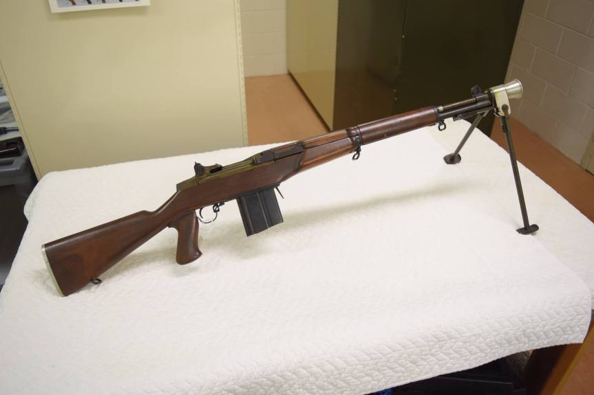
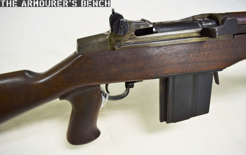
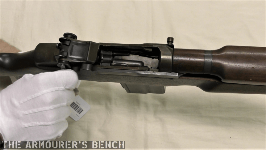
Externally, the rifle has a number of instantly recognisable distinctions from the standard M1 Garand. It has a reshaped stock with an added pistol grip, a proprietary box magazine and a combined bipod and conical flash hider. If we look closer we’ll notice that the stock has a swell just ahead of the breech, flaring out in an almost triangular bulge. These changes to the stock also distinguish this rifle from Winchester’s other select-fire M1 adaptations, which retain the standard Garand stock profile.

From the patents available combined with an examination of the rifle we can learn a lot. We cannot rely on patents to tell the whole story of the rifle, however, as many of the elements that make up the weapon appear to have gone unpatented. The substantial external and internal changes made to the rifle suggest that this was not an attempt to adapt the M1 with a minimal number of component parts changes but rather an effort to generally improve the rifle, making it conducive to fully automatic fire.

DSC_0231
Detail photo showing the rifle’s pistol grip, altered stock and magazine (Matthew Moss)

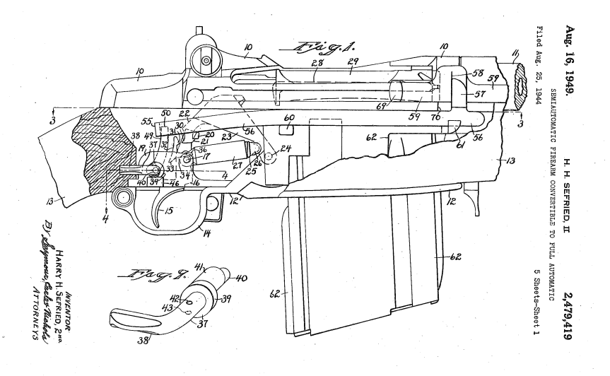
In summer 1944, Winchester’s CEO Edwin Pugsley directed Sefried to begin work on a select-fire conversion for the M1, to rival those being developed at Springfield Armory and Remington. Winchester’s select-fire Garand went though a number of iterations which resulted in two patents from Sefried. The first, filed in August 1944 (US #2479419), incorporated an elongated sear actuating lever and a selector on the lower, right side of the receiver. Winchester’s first attempts at a select-fire M1 conversion resulted in rifles with extremely high, uncontrollable rates of fire of over 900 rounds per minute. Sefried filed a second patent later in January 1948 (US #2464418) which used a catch to hook the sear. The rifle we are examining appears to have yet another select-fire system, one for which I have so far been unable to find a corresponding patent for. Winchester’s work on the select-fire adaptation came to a halt with the end of the war. It appears, however, that Winchester again began to work on adapting the M1 in the late 1940s, with Sefried again working on the project, filing his second select-fire mechanism patent in 1948 (US #2464418).

US2479419 sefrieds 1st patent
Sefried’s 1949 patent for another select-fire M1 conversion (US Patent Office)

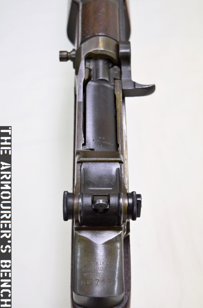
The rifle’s receiver was originally a standard Winchester-made .30-06 M1 with a serial number of 1,627,456. This means its wartime production gun, dating from May 1945. It would appear that rather than the rifle being lifted from the rack finished, it seems that it was earmarked for prototype development because the receiver forging lacks the cuts/forgings needed for the en bloc clip release lever. This makes sense if it was known that the receiver was destined for use in a prototype which fed from a box magazine. However, the timeline of the rifle gets more complex when we consider that it was a late-war production rifle. There are a number of possibilities. The rifle may have been simply set aside for internal prototype work in May 1945 and not used until a T65 chambered rifle was developed later. Alternatively, it is possible that the rifle was converted during the initial attempts to create a select-fire M1 but was later rechambered from .30-06 to the new developmental T65 round.

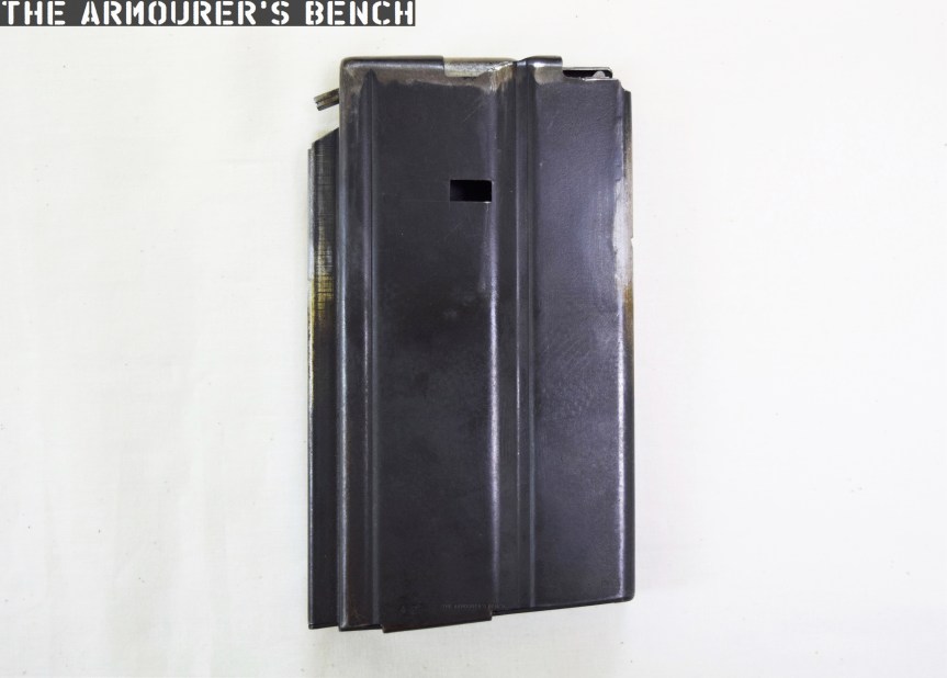
This prototype’s trigger guard assembly, which also comprises the magazine well floorplate, is a self-contained assembly and does not interact with the weapon’s trigger mechanism or action. While Sefried had a patent for his own magazine system (US #2386722) this rifle uses a slightly different magazine release and floorplate, which is similar to one seen in Stefan Janson’s 1956 patent for a stripper clip-loading box magazine for the M1 (US #2894350). The magazine used in this prototype, however, is not the same as Janson’s. It has fixed feed-lips and a projection at its rear which appears to house an anti-tilt tab for the follower.

DSC_0234
The rifle’s magazine (Matthew Moss)

The rifle does not to appear to use the full-automatic system seen in either of Sefried’s patents.  Similarly, the safety selector is located on the left side of the receiver, forward, in line with the breech. It has two positions with an arc of about 90 degrees. This position does not match Sefried’s patents for select-fire conversion, however, it does match the position patented by David Marshall Williams but not Williams’ selector’s orientation of travel. I have been unable to find a patent which matches this rifle’s selector or method fully-automatic conversion.

DSC_0224
Left-side view of the rifle’s receiver showing the fire-selector (Matthew Moss)

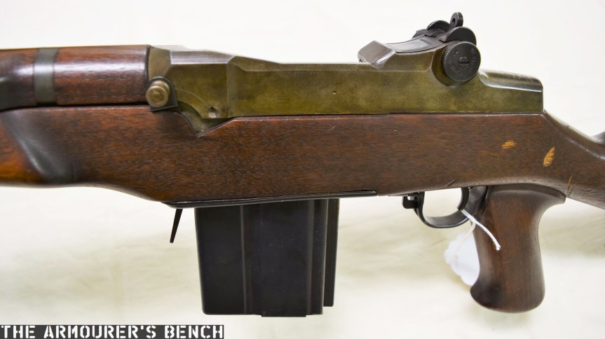
The pistol grip is an interesting addition as neither of the other Winchester select-fire prototypes nor the original select-fire Springfield prototypes incorporated one. Visually it is very similar to that seen on the later Italian Beretta BM 59 Mark II.  In an effort to lighten the rifle the prototype also has an aluminium buttplate. One of ingenious internal changes is the milling of the bottom of the barrel flat, this not only has the effect of lightening the rifle but also allows a new, straight operating rod to travel rearwards under the barrel. How this impacted on the barrel’s harmonics is unclear. The rifle certainly feels lighter and handier (when unloaded) than you would expect, weight is estimated to be around 7 or 8 lbs.


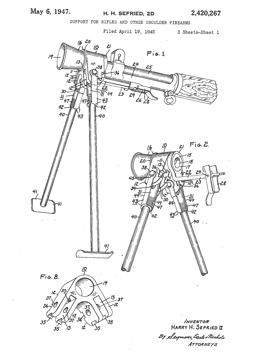
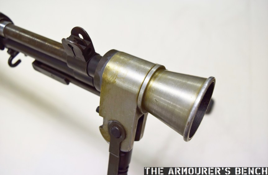
The bipod, patented by Sefried in April 1945, (US #2420267) comprises a pair of tube steel legs, which have a set height, and a conical aluminium flash hider. The legs are spring-loaded and the entire assembly attaches via a latch which seats over the rifle’s bayonet lug. The bipod is the only element of this rifle that can be attributed to Sefried directly. And by the bipod’s very nature of attachment may simply have been attached later.

Sefried's April 1945 bipod and flash hider patent (US Patent Office)
Sefried’s 1947 patent for the bipod-flash hider (US Patent Office)

The best documentary source available for the prototype is the entry in the Winchester Factory Museum’s collection inventory offers some tantalising clues but no definitive answers:

#1504    U.S. Model M-1 rifle (Garand)
Cal. 30-06; experimental semi or full auto.
3rd type 20 shot box mag.
Special butt plate for shoulder rest
Bipod and aluminum flash hider attached
From H. Sefried 10-26-45

The suggestion that the rifle is chambered in .30-06 is seemingly an error given the internal changes made to the rifle. ‘3rd type’ suggests an iterative development of the rifle’s magazine while “special butt plate for shoulder rest” may allude to the aluminium butt plate but the prototype’s plate has nothing resembling a ‘shoulder rest’, instead it is a simple chequered aluminium plate about 5mm thick. While ‘From H. Sefried 10-26-45’ may refer to the whole rifle, I believe it more likely refers simply to his bipod.

DSC_0221
A close up of Sefried’s bipod-flash hider (Matthew Moss)

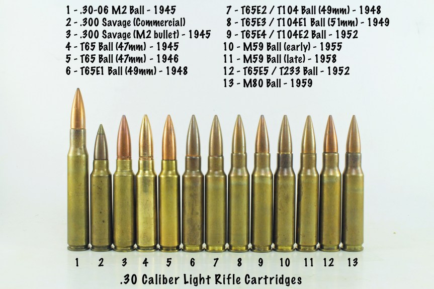
The prototype appears to be chambered in an iteration of the .30 Light Rifle round, which later became known as the T65. The rechambering was achieved by installing a metal block which shortened the magazine well. Unlike earlier Winchester select-fire conversions this rifle feeds from a proprietary magazine designed to feed the T65 round. This magazine does not appear to closely follow the pattern used by Winchester on several other designs during the period. The projection from the rear of the magazine slides along a channel cut in the metal magazine well block. It has font and rear locking shelves, with the front shelf acted on by the magazine release lever.

DSC_0229
A look at the rifle’s receiver and serial number markings from above (Matthew Moss)
S1230030_Moment
With the action open. Note the magazine insert at the rear of the magazine well (Matthew Moss)

Development of the .30 Light Rifle round, which would eventually become 7.62x51mm, began in 1944, with the round first being referred to as the T65 in 1946. It appears that the rifle is chambered in a version of the T65 cartridge, but which iteration exactly is unknown. However, its chambering does support the theory that the prototype may date from 1947-48. The T65 didn’t take on the now standard 7.62x51mm dimensions until 1949 in the form of the T65E3 round but without a chamber casting it is impossible to know the rifle’s exact chambering.

yn4QSZC
A photo representing the evolution of the .30 light rifle round (Courtesy of DrakeGmbH)

While Winchester continued to work on adapting the M1 Garand into a select-fire rifle none of their rifles were seriously considered by US Ordnance. At the same time John Garand was working on his own series of select-fire, magazine-fed prototypes (the T20 series) at Springfield while Remington had also been awarded a contract to develop a similar rifle, tested under the designation T22. These projects subsequently gave way to a number of other designs, all chambered in the T65 round, including the T25/47, T44 and T48. These were all tested before the Garand-influenced T44 was eventually selected in 1957, becoming the M14.

Addendum:

Harry Sefried II served in the US Army Air Corps during World War Two before joining Winchester as a firearms designer in 1944. In the 1950s he left Winchester to become Ruger’s chief engineer until he retired in 1979. He died in 2005, aged 84.


If you enjoyed the video and this article please consider supporting our work here. We have some great new perks available for Patreon Supporters.


Bibliography:

Patents:

‘Semiautomatic Firearm Convertible to Full Automatic’, H.H, Sefried, US Patent #2479419, 25/08/1944, (source)

‘Box Magazine Latch Mechanism for Repeating Firearms’, H.H, Sefried, US Patent #2386722, 29/09/1944, (source)

‘Support for Rifles and Other Shoulder Firearms’, H.H. Sefried, US Patent #2420267, 19/04/1945, (source)

‘Fire Control Mechanism for Automatic and Semiautomatic Firearms’, H.H, Sefried, US Patent #2464418, 02/01/1948, (source)

‘Strip Clip for Loading Box Magazines’, S.K. Janson, US Patent #2894350, 11/04/1956, (source)

Secondary Sources:

‘The Select-Fire M1 Garand’, F. Iannamico, Small Arms Review, (source)

Harry H. Sefried II Obituary, Hartford Courant, June 2005, (source)

‘Light Rifle, Part IV: The M1 Garand Learns To Rock And Roll’, TFB, Nathaniel F., (source)

Cartridge History for the Day – .30 Light Rifle, (source)

‘Winchester Proto-M14 Rifle’, Forgotten Weapons, (source)

Heckler & Koch HK53

In 1968 Heckler & Koch launched the HK33, chambered in 5.56x45mm, to compete with Colt’s AR-15/M16. The HK33, and later HK53, used the same roller-delayed blowback action developed for the G3 in the mid 1950s. However, few major contracts were forthcoming with the German military opting to continue using the 7.62x51mm G3.

11111111111
Heckler & Koch HK53 (with ‘navy’ lower reciever) brochure c.1987 (source)

Due to the modularity of the HK33′s design users could replace the butt of the standard rifle with a collapsible telescopic metal stock. H&K also subsequently designed a carbine version of the full-length HK33, the HK33K with a telescopic metal stock and 12.7 inch barrel. In the mid-1970s H&K began development an even shorter version. The result was essentially an intermediate calibre submachine gun similar to the Colt Commando and the Soviet AKS-74U. H&K designated this new weapon the HK53, it used the same telescopic stock as the HK33K and MP5 and a cut down 11 inch barrel, the HK53 also utilised a polymer forearm similar to the MP5s.

1
Contemporary promotional photos dating from 1985 (source)

Like the HK33, the HK53 fed from 25, 30 or 40 round box magazines. The weapon weighed just over 3kg (7lb), almost a 1 kg less than its parent rifle the HK33. Unlike the HK33, the HK53 has a four prong flash hider. A number of police forces and militaries adopted the HK53 for a variety of roles. Special forces units around the world including the British SAS, Royal Military Police Close Protection Unit and Royal Marines, designated the L101A1 in British service, who typically used it during close protection duties and operations involving close quarter battle.

2
Contemporary promotional photo dating from 1985 (source)

As shown in various MoD Equipment Failure Reports dating from the early 1990s the HK53’s in British service suffered from repeated damage and failure of the carbines’ locking rollers. This issue arose when using a number of different ammunition types including brass cased blank ammunition (H&K recommend the use of their proprietary blank cartridges). Following a meeting between the Army Technical Support Agency’s Directorate of Engineering and H&K a new design for the locking pieces were developed. These changes “increased the roll of blowback force during the unlocking phase… in turn this will reduce the mean energy of the recoiling mass of breech block and carrier” this was intended to reduce bolt bounce. The Royal Military Police Close Protection Unit’s L101A1’s were also fitted with a new two stage buffer within a fixed stock. In British service the L101 was replaced by the L22A2 carbine and the L119A1 (C8 Carbine).

DSC_0843
HK53, stock collapsed, (Matthew Moss)

Due to its short length the HK53 also found itself pressed into the port-firing weapon role. Designated the HK53 MICV in this role the foregrip and stock was removed and a specially designed endcap and a spent case bag could be attachment. During its service life the HK53 went through a series of changes to furniture mouldings, buttstock types and fire selector options. It remained in production into the early 2000s, when Heckler & Koch replaced the HK33 and HK53 with the G36 and G36K.

If you enjoyed the video and this article please consider supporting our work here.


Technical Specifications (from 1987 H&K brochure):

Length (with stock extended): 76.5cm (30in)
Weight (collapsible stock, unloaded): 3.35kg (7.4lb)
Barrel Length: 22.5cm (8.5in)
Action: Roller delayed blowback
Calibre: 5.56x45mm
Feed: 25, 30, or 40-round box magazine
Cyclic Rate: approx. 700 rpm


Bibliography:

The World’s Assault Rifles, G.P. Johnston & T.B. Nelson, (2010)

Heckler & Koch HK33 & HK53 manual (source)

HK53 factory colour brochure, 1987, (via Small Arms Review Reference Library)

Itemised list of L101A1’s which suffered damaged locking rollers, MoD Equipment Failure Report, 15 Nov. 1994, (via Small Arms Review Reference Library)

Army Technical Support Agency report on receiver damage to HK53 and G3 rifles, 1996,(via Small Arms Review Reference Library)


Please do not reproduce photographs taken by Matthew Moss without permission or credit. ©The Armourer’s Bench 2018.

Photos: Heckler & Koch G11 ACR

Here are a selection of external photographs showing the H&K G11 submitted to the US Army’s Advanced Combat Rifle trials in the mid-1980s. You can watch our introductory video featuring two G11s here.

Note: While this collection of images covers only the externals of the G11, rest assured that if and when we get the opportunity we will follow this up with hi-res photographs of the weapon disassembled!  UPDATE – We disassembled a G11!

1
Right side view of the G11, note the muzzle plug inserted into the barrel (Matthew Moss)
2
Left side view of the G11, note the small window in the magazine showing the follower spring (Matthew Moss)
3
Close up of the right side of the G11’s fire selector (safe – semi – hyperburst – full auto), trigger and grip which enclosed a ‘control brush’ used to check the chamber was empty and in cleaning (Matthew Moss)
4
Left side close up of the G11’s selector, trigger and pistol grip – note also the rifle’s designation,  serial number, presumably manufacturing date and calibre moulded into the weapon’s casing (Matthew Moss)
5
A view of the G11 from above – note the alignment of the magazine and the lack of later additional channels for spare magazines seen in some G11K2s (Matthew Moss)
6
Close up of the G11’s foregrip and sling loop and an empty magazine loaded into the weapon  (Matthew Moss)
7
Close up of the weapon’s rotating ‘cocking handle’and pressure valve, note the white arrow indicating the direction to twist the handle to cock the weapon – the plastic folding handle on this example has sadly broken off, a common issue with G11s (Matthew Moss)
8
Close up of the left side of the G11’s ‘central part’, as HK described it, into which the barrel and breech assembly slide (Matthew Moss)

Many thanks to the collection, which wishes to remain anonymous, that holds this example of the G11 for the opportunity to examine, photograph and film it.

If you enjoyed the video and this article please consider supporting our work here.


Please do not reproduce photographs taken by Matthew Moss without permission or credit. ©The Armourer’s Bench 2018.

An Introduction to the Heckler & Koch G11


Vic kicks off his series looking at the US Army’s ACR trials rifles with a look at, not one but two versions of, Heckler & Koch’s advanced caseless ammunition assault rifle – the G11. This video is an introductory overview, we’ll be delving into the G11’s insanely intricate and wonderfully complex action in later videos!

DSC_0131
HK ACR 4.92x34mm G11 (Matthew Moss)

There are few experimental weapons that have cultivated myth and reputation like Heckler & Koch’s G11. The product of decades of research and development into what was hoped would be the next evolutionary step in small arms design. The G11 was Germany’s attempt to combine advanced caseless ammunition with a weapon system which could increase the average infantryman’s hit probability. The G11’s action has three distinct modes of fire and uses a complex action and buffer/recoil system to achieve a high rate of controlled fire.

The program began in the late 1960s as part of a NATO initiative, however, it became a primarily Bundeswehr project and over two decades the design evolved substantially. The project sought to increase the hit probability of the individual infantryman. Heckler & Koch’s approach to this problem was the most radical. Working with Hensoldt to develop an integrated optical sight and with Dynamit-Nobel to create a new kind of ammunition.

Numerous studies and theoretical designs were worked up but by the mid-1970s the base design of what would become the G11 was cemented. The design team included Gunter Kastner, Dieter Ketterer, Tilo Moller and Ernst Wossner – all of whom are credited in H&K’s 1976 patent protecting the G11’s rotary action.

The G11 went through dozens of iterations throughout the 1970s and 80s, with the first firing prototypes ready by 1974. Both the design and the ammunition also went through a number of changes.

g11round5
Diagram showing the composition of the G11’s caseless ammunition (source)

The revolutionary ammunition was developed by Dynamit-Nobel AG.

The 4.73x33mm round which was finalised comprised of a solid propellant material body which encased a primer, booster, projectile and a plastic nose cap. Dynamit-Nobel developed the High Ignition Temperature Propellant (HITP) in an effort to prevent accidental ignition (cook-off) of the ammunition’s outer propellant body.

The G11 fed from 45 or 50-round horizontal, single stack box magazines which fed rounds into the action at 90-degrees. The rounds were then rotated into alignment with the breech by the rifle’s action.

The rectangular shape of the Dynamit-Nobel ammunition was more efficient and better suited to storage than conventional circular rounds. The positioning of the magazine along the top of the weapon, parallel to the barrel, also in theory helped minimise the rifle’s profile and reduce encumbrance for the soldier equipped with the weapon.

The G11 is a gas-operated weapon with gas being tapped from the barrel, to cycle the rifle’s cylinder drive system, which rotated the breech through a series of cams and gears. At the heart of the G11 is a complex rotary action. Rotating actions themselves are not a new concept with the earliest dating back to the 17th century, such as the Lorenzoni system.

The G11’s rotating breech was patented in late 1976 by Heckler & Koch. While our initial video does not go into detail on how the G11 operates, we will be covering this in later videos, this article will explain the action in more general terms.

1
H&K’s early patent showing the G11’s rotating action – note the early incarnation of the ammunition with the projectile protruding from the propellant block (source)

Below are two diagrams showing the internal layout and major components of the G11 from a March 1982 draft of the ‘Rifle, 4.92mm, ACR’ armourer’s manual (source). It shows the major assembly groups and also a component list for the breech assembly.

From the diagram we can see the various action parts which feed the projectile into the breech, lock the action and ignite the round. We can also see the counter-recoil system beneath the barrel.


This slideshow requires JavaScript.

The G11 used a counter-recoil buffer mechanism to allow high rates of burst fire. When firing three round bursts the weapon send the rounds downrange at a rate of ~2,000 rounds per minute, only when the last round has left the barrel does the barrel and action begin to recoil inside the stock along a central guide. When in sustained fire the rate of fire is closer to ~460 per minute.

g11recoil
H&K promotional diagram showing the G11’s mounted recoil system (source)

The buffer spring below the barrel is compressed as the recoiling barrel and breech assembly moves. In sustained fire the buffer spring is partially compressed with each round, but in burst fire the buffer is compressed to its maximum hitting before the buffer housing (which is when recoil from the burst is felt by the operator), this is described as having the barrel and breech assembly ‘float’.

To ready the weapon to fire a magazine was loaded into the magazine channel on top of the G11, a magazine dust door, which automatically closed when unloaded, was depressed as the magazine was pushed home. The cocking handle on the left side of the butt was then actuated. The operator rotated the handle 360-degrees counter-clockwise until the weapon was cocked (essentially like winding a clock). The same process will eject any rounds left in the chamber once the magazine has been removed.

Gas tapped from the barrel cycles the cylinder drive system with gas pushing a piston back to act on a series of gears which rotated the rotary breech from horizontal to vertical to allow a new cartridge to drop into the breech. There was a vent for high pressure gas underneath the butt stock this prevented pressure build up and mitigated some of the thermal build up.

6626263
Members of the Gebirgsjäger (Bundeswehr alpine light troops) on the march with G11s (source)

The G11 K1 was tested by the German Army in the late 1980s with adoption planned for the early 1990s. Heckler & Koch continued to develop the G11, entering the G11 K2 into the US Army’s Advanced Combat Rifle (ACR) trials alongside entries from Steyr, AAI and Colt [all of which we will examine in upcoming videos]. However, the fall of the Berlin Wall in 1989 and the collapse of the Soviet Union in 1991 meant that West Germany no longer had the huge amount of funds needed to field the G11. At the same time the ACR program ended inconclusively and the G11 project was finally abandoned.

The extreme complexity of the design, the inadequacy of the weapon’s ergonomics and its inevitably high production cost casts doubt on whether the G11 would ever have seriously been considered for widespread adoption. Regardless of this the G11 is a fascinating footnote in small arms history representing a false start along a technological avenue which, with the Lightweight Small Arms Technologies (LSAT) program, may still prove fruitful. Heckler & Koch and Dynamit-Nobel’s ambitious design marks one of very few serious and potentially successful attempts engineers to overcome the plateau that firearms technology is currently stuck on.


Stripping the HK G11

DSC_0997
G11 ACR disassembled to its major assemblies (Matthew Moss)

Matt recently had the opportunity to disassemble a G11 and get a look inside the action. In this special video and accompanying full-length article he explains how the rifle strips and how it works! Check out the video here.

If you enjoyed the video and this article please consider supporting our work here.


Technical Specifications (from 1989 H&K Brochure):

Length: 75cm (29.3in)
Weight (unloaded): 3.8kg (8.4lb)
Barrel Length: 54cm (21.3in)
Action: Gas-Operated, rotary breech
Calibre: 4.73x33mm
Feed: 45 or 50-round, single stack, box magazine
Cyclic Rate: sustained fire: ~460rpm /  3-round burst: ~2,000rpm


Bibliography:

Die G11 Story. Die Entwicklungsgeschichte einer High-Tech-Waffe, W. Seel, 1993

‘Shoulder Arm with Swivel Breech Member’, US Patent #3997994, 21 Dec. 1976, (source)

‘Automatic or Semi-Automatic Small Arm’, US Patent #4078327, 14 Mar. 1978, (source)

From the Small Arms Review Archive:

HK G11- ACR. Armourer’s Manual for Maintenance of Repair of Rifle, 4.92mm, ACR, March 1989 (source)

‘Rifle, 4.92mm, ACR’ Operator’s Manual (source)

HK G11 Caseless Ammunition Weapon System. The G11 Rifle. HK Factory Brochure, 1989 (source)

Our thanks to the collections that hold these examples of the G11. While one wishes to remain anonymous, we would like to thank the Dutch Military Museum for access to their G11.


Please do not reproduce photographs taken by Matthew Moss without permission or credit. ©The Armourer’s Bench 2017.