Experimental PIAT Universal Carrier

In late 1944, a platoon of Canadian sappers built an intriguing in-field adaptation to a Universal Carrier (sometimes known as Bren Gun Carrier) – they developed a PIAT Carrier.

The 16th Field Company, Royal Canadian Engineers were attached to the 3rd Canadian Division during operations in northwest Europe. Each Canadian division had a Divisional Royal Canadian Engineers Group attached to it, made up of several field companies. In November 1944, the 16th Field Company, RCE was located near Nijmegen.

The ‘PIAT Carrier’ (Library and Archives Canada)

The experiments which led to the PIAT Carrier were embarked on after the division’s commander, Major General Daniel Spry, put out a directive for ‘harassing weapons’ to be developed. The interesting adaptation was somewhat reminiscent of a miniature Soviet Katyusha or Commonwealth Land Mattress. While similar in concept to these multiple rocket launchers, it is important to remember that the PIAT isn’t a rocket launcher – but a spigot mortar.

Loading a Land Mattress multiple rocket launching system (IWM)

The Canadian engineers mounted the PIATs in two rows at an obtuse angle at the rear of the Universal Carrier, presumably for use in a limited bombardment role. The idea behind the outfitting of the Carrier appears to have been to utilise the PIAT in its secondary, indirect role as a mortar, perhaps for fire against buildings or to harass enemy positions. From photographs taken in the field we can see that the engineers of 16th Field Company fixed the PIATs into a wooden frame at the rear of the Carrier, they appear to have had their monopods removed, but some still appear to have their slings fitted.

Developing the PIAT Carrier

From further research and some digging through the 16th Field Company’s War Diaries, I found reports on the adapted carrier and even some diagrams showing how the bombs landed. The diaries also reveal that the Universal Carrier was not the first vehicle the PIATs were mounted on – the first tests were carried out on a truck.

Front Cover – 16th FC, RCE, Nov. 1944 War Diary (Library & Archives Canada)

In the war diary we get the first mention of the PIAT battery in the entry for the 15th November 1944. It reads:

“The GOC directed that each arm of the service should be prepared to devise some means of harrassing the enemy during the holding role of the Div present area and to act as a counter-measure to the Moaning Minnies [Nebelwerfer] employed by the Germans. The ORE decided that the Sprs could make use of the 24 PIAT’s held by the C in Div Engre. The tentative Idea being that these be mounted on a veh, or two vehs, that they be fired mechanically and possibly simultaneously with a multiple mortar effect.  Lieut. Cameron and No. 1 Plattoon [sic] were given the task, experiments to be carried out tomorrow for this purpose all PlATs and ammunition were called into this Company from Div Engrs.”

The next day on the 16th November the diary recorded:

“Lieut. Cameron made a number of tests with his PIAT platoon In conjunction with the N.S.R. and found that the maximum range that could be attained was 300 yds. Maj Main will discuss this matter with CRE tomorrow.”

Then several days later on the 19th November:

“Lieut. Cameron gave a demonstration of the capabilities of the PIATs used to fire with a mortar effect, 18 PIATs were mounted in racks on one vehicle at an angle of 45 degrees and fired simultaneously. There was no jar to the vehicle, Max range obtained was 300 yds against the wind and 400 Yds with the wind, detonation of salvo was all within one second of time and covered an area 25ft in length by 15ft width.”

This short report concluded by explaining why the PIAT Carrier may not be field practical, noting that “The plan is not practicable at present as areas of firing are not available that would permit the vehicle moving up to 300 yds from target before firing.”

The first major test is described in a report dated 21st November. A total of 22 PIATs were available to Lieut. Cameron’s platoon. They mounted 18 PIATs in racks on the bed of a Ford Canada 60 cwt (60 hundredweight – 3 ton) truck, with the remaining 4 as spares.

The report explains that steel wasn’t available so wood was used for the racks. Which they also believed would have a “cushioning effect serving to shield the truck to some extent from the shock of recoil.”

The 18 PIATs were arranged in three rows of six PIATs with PIATs spaced 1 foot apart next to one another, with four feet between each row. The PIATs were angled at 45-degrees by a wooden plank attached to the side of the truck bed with the butt of the weapon bolted down under wooden struts.

With no photos of the ‘PIAT Truck’ here’s a quick fun artists impression (Matthew Moss)

To fire the weapons rods were run along the rows aligned with the weapons’ triggers with bars of 1/2in steel running back between each one and back towards the font of the truck where the operator was stationed. The report describes this set up as ‘satisfactory’.

In the first test all three rows of PIATs were fired at the same time. The report’s findings note that in the first test all but one of the weapons fired, the bombs were in the air for an estimated 4 to 5 seconds and the time between the first and last bombs striking the ground was approximately ½ to 1 second.

The blast radius of the individual bombs is noted as 5 feet with 6 to 9 inches of penetration through gorse and sandy loam soil. The range was found to be 310 yards against the win and 400 yards with it. The wind was noted to be travelling as 20-25mph. From the diagrams accompanying the report we can see that the beaten zone had a maximum diameter of approximately 54 to 60 feet. With a mean point of impact around 15 to 18 feet wide.

A fall-of-shot diagram from the November RCE report, 16th FC, RCE, Nov. 1944 War Diary (Library & Archives Canada)

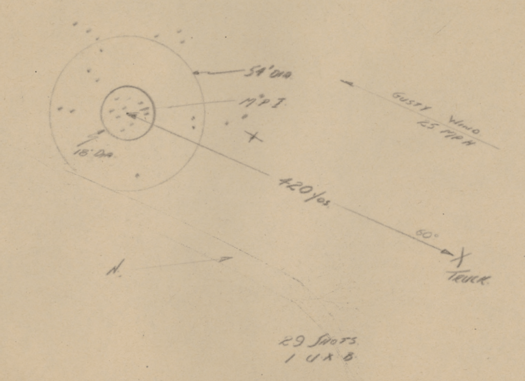
The second test saw the sappers fire two full salvos to test how quickly the rig could be reloaded. The reload time between salvos was recorded as 1min 20seconds. The second salvo saw 6 of the PIATs fail to fire due to a mechanical failure when one of the trigger rods broke. The extreme range achieved during this second firing was 420 yards with the wind.

During this first field test of the truck mounted system, a total of 65 bombs were fired and only one failed to explode down range. The racks were strengthened and the trigger rod repaired, it was also concluded that the racks could be spaced closer together without “effecting the pattern of the beaten zone” down range.

There is no further mention of the testing in the war diary during November but progress definitely appears to have been made, an entry on the 16th December notes:  

“The use of PIATs mounted on a vehicle has had further experimental trials, 15 PIATs have been mounted on a Bren Carrier by this unit and a trial shoot was held today, Against a slight wind a range of 310 yards was attained with the area of burst covering 25 ft deep and 50 ft wide, no recoil was felt in the carrier.”

The last mention of the PIAT Carrier comes on 30th December:

“The carrier mounted with 15 PIATs was on trial during the afternoon before an audience consisting of the GOC and Officers of the Div. All visitors were impressed by the display. A range of 350 yds was attained and the accuracy on target was good.”

There are no further mentions of the PIAT carrier in the diary. It seems that development of the idea didn’t progress into 1945, by early February, the 16th FC RCE were involved in Operation Veritable. It appears that the operational requirement no longer existed.

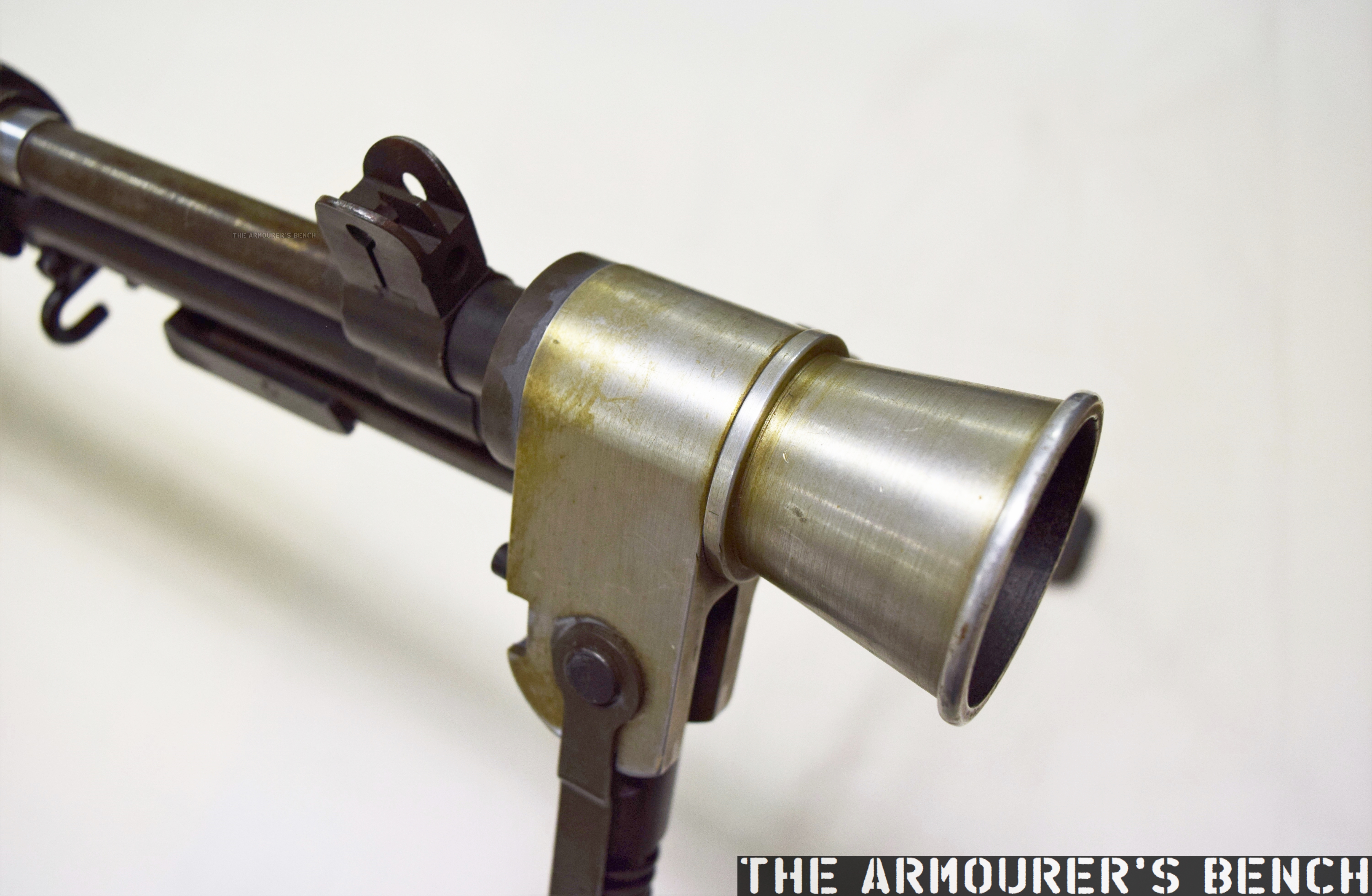
Lets take a closer look at how the adaptation was done. From the available photos, which were probably taken in mid-December 1944, we can see the trigger bar that was passed through the trigger guards of each of the PIATs, with the bar resting at the base of the trigger, it is unclear from the available photographs but this may have allowed the weapons to be fired either by row or all together.

Close up photograph of the racks holding the PIATs – note the trigger bars, wooden frames and the PIATs’ white in-direct fire aiming lines (Library and Archives Canada)

The sappers have built a wooden platform onto the back of the carrier with welded metal brackets holding the pieces together. The PIAT’s are held between two wooden cross pieces that have been bolted together. There’s a strip of metal running around the edged of the wooden frame that has been twisted 90-degrees and then welded to the carrier. It is also worth noting that all of the PIAT’s have had their butt pad covers removed and the feet of the PIATs’ rear end caps have been secured with a pair of brackets either side.

The PIATs in their racks (Library and Archives Canada)

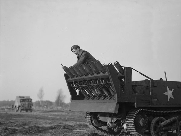
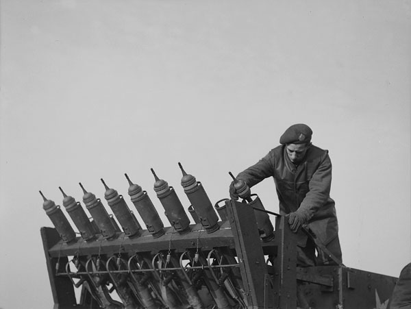
In the photograph above we see all of the PIAT’s held in their racks with their sights folded down, slings still attached, and we get a good view of the white indirect fire aiming lines. At the bottom of the photo we can see a trigger bar which when pulled appears to pull the triggers of the whole row at once. As an aside, note that the carrier has a ‘crooked’ Commonwealth allied star – to differentiate it from the US allied stars which were aligned with their top point at 12 o’clock  

It appears that the battery of PIATs was aimed by reversing the Carrier towards its target, that would certainly have been challenging and a fairly dangerous task given the relatively short range of the PIAT even when used as a light mortar.

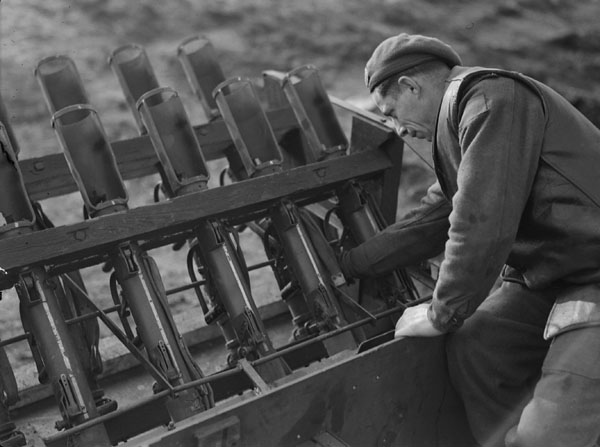
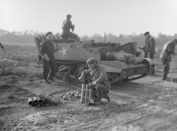
From this photograph below, of a Canadian sapper loading the PIATs, we can see all of the spigot tube stoppers dangling on their chains. The sapper is loading the bomb from the front of the bomb support tray and has angled the tail up to slide the projectile loading clip into the projectile clip guides on the face of the PIAT.

Loading the PIATs (Library and Archives Canada)

It also appears that sandbags are being used as a counterweight at the front of the carrier. The combined weight of the PIATs and their bombs (about 555 lbs) as well as the weight of the frame would have been considerable.

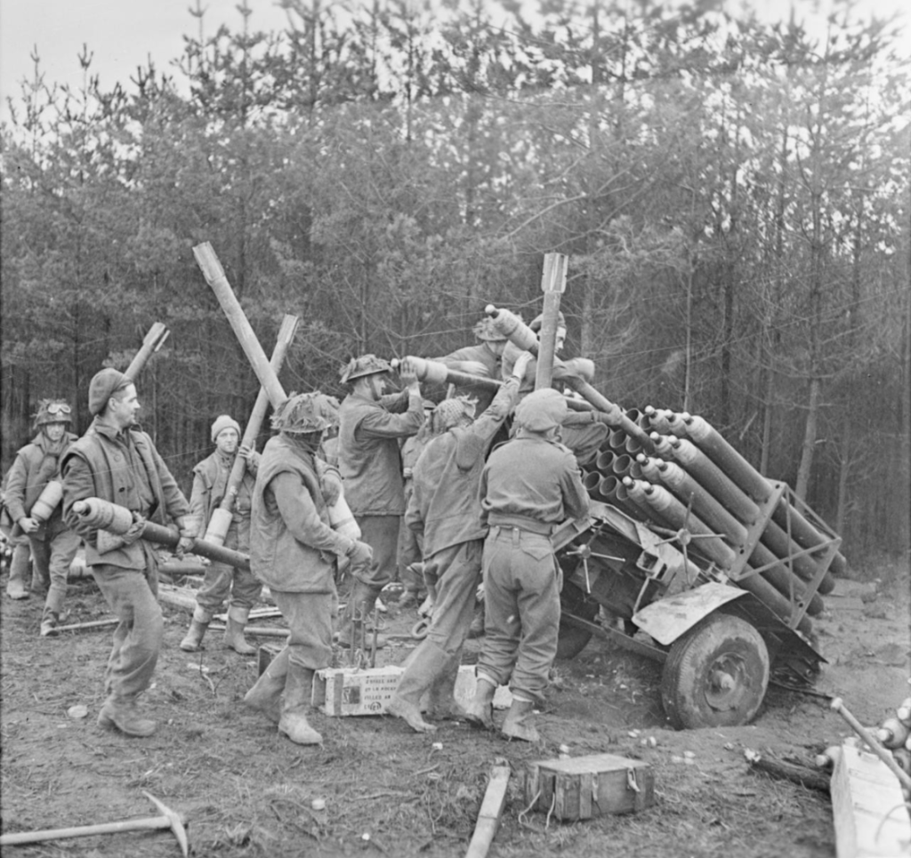
In the final photograph below we see the sappers preparing the battery to fire with a sapper in the foreground removing bombs from three bomb carriers. While in the background on the right we can see another sapper carrying bombs forward from another set of bomb carriers. I would guess that it was perhaps decided to mount 15, rather than an even number, PIATs as the bomb carriers held three round each – with 5 bomb carriers needed to reload the battery of PIATs.  

Readying the PIAT Carrier for testing (Library and Archives Canada)

While sadly we don’t have any footage of the test we’re very lucky to have this selection of brilliant photographs courtesy of the Library and Archives Canada. It would seem that the limited range of the PIATs made the concept of a PIAT Carrier too impractical to field – but a maximum range of 400 yards may have offered some interesting tactical options for dealing with defended buildings or field works.
Perhaps need for a response to the enemy Nebelwerfers was answered by the introduction of the longer ranged, harder hitting Land Mattress. Despite this the ‘PIAT Carrier’ is a fascinating piece of resourceful engineering – an innovative, field-expedient adaptation that brought together two classic bits of British and Commonwealth kit – the PIAT and the Universal Carrier.


If you enjoyed the video and this article please consider supporting our work here. We have some great perks available for Patreon Supporters. You can also support us via one-time donations here.


Bibliography:

War Diaries of 16th Field Company, Corps of Royal Canadian Engineers, Library & Archives Canada (source)

All photographs courtesy of Library & Archives Canada (source)


The Sterling Submachine Gun – Magazine

In May 1946, George Patchett patented a new curved magazine which would become one of the Sterling’s most recognisable features. It addressed some of the serious shortcomings of the STEN’s magazine.

George Patchett’s machine carbine, Which later that came to be known as the Sterling, had been initially designed to use the standard STEN magazine. This makes complete sense as not only was the STEN’s magazine readily available but it stood to reason that the British Army would prefer to retain the large number of magazines it already had in stores.

Capture 04_Moment
A Sterling L2A3 with a disassembled Sterling commercial-pattern magazine (Matthew Moss)

The STEN’s magazine is, however, the gun’s weakest link. Its a double-stack, single feed 32-round magazine was difficult to load and could feed unreliably when not looked after. The Patchett prototype performed well during initial testing in 1943, but later sand, mud and arctic testing of the Patchett against various other submachine guns highlighted the limitations of the STEN magazine – regardless of the weapon using it.

Capture 04_Moment
Patchett’s Original Toolroom prototype (Matthew Moss)

At some point in 1945, Patchett developed a series of new magazines, a 20-round ‘Patrol’ magazine, a 40-round ‘Standard’ magazine and a 60-round ‘Assault’ magazine. By late 1946, these had been superseded by a 35-round magazine designed to fit into the basic pouch of the British Army’s 1944 Pattern web equipment.

Patchett addressed the STEN magazine’s shortcomings by designing his magazine with a curve which allowed the slightly tapered 9×19mm rounds to feed more reliably. He also replaced the traditional magazine follower with a pair of rollers which minimised friction and allowed dust, grit and dirt to be rolled out of the way improving reliability. Patchett’s magazine was designed so it could be economically stamped from sheet metal and folded and spot welded into shape. It was also simple to disassemble for cleaning and requires no tools for disassembly.

Capture 04_Moment
George Patchett’s US patent for his roller magazine follower (US Patent Office)

By 1951 the magazine had been largely perfected but a trials report suggested that the magazine’s feed lips needed to be reinforced. Despite this the Sterling was said to be “better than all other weapons tested.” Following further development and testing the L2A1 Sterling submachine gun was eventually adopted in the summer of 1954. We will cover the development, adoption and service of the Sterling at a later date.

In 1952, Patchett added a pair of strengthening ribs to the inside of the magazine which also further reduced friction on the rollers. He also replaced the oval follower spring with a more efficient circular one with the ribs acting to hold it in place. The final production magazines held 34 rounds and were substantially easier to load than the earlier STEN’s.

Capture 04_Moment
Patchett’s US patent for his circular magazine spring held in position by the stamped magazine body (US Patent Office)

The L2A1/MkII, introduced in 1954, was the first Patchett to incorporate an angled magazine housing which improved feeding reliability from the Patchett’s patented curved, double stack, double feed magazine. The Sterling’s magazine housing was angled forward slightly at 82-degrees.

Capture 04_Moment

The magazines used by the British military differed from Patchett’s design. The British government, perhaps unwilling to purchase the rights to manufacture Patchett’s design, developed the ‘Magazine, L1A2’. Nearly two million of these were built at Mettoy, Rolls Razor, ROF Fazakerley and the Woolwich Royal Laboratories. The L1A2 magazine was slightly simpler to manufacture but retained Patchett’s roller follower while the magazine’s body was made from two, rather than four, pieces of stamped steel and electrically welded together. The government-designed magazine is 5cm (2 inches) longer than Sterling’s magazines.

Capture 04_Moment
disassembled Sterling commercial-pattern magazine (Matthew Moss)
Capture 04_Moment
Rear edge of the magazine, with Sterling factory markings (Matthew Moss)

The example magazine seen above and in the accompanying video is Sterling-made and is marked with the company name and patent numbers. We can see the folded sheet metal construction and the overlaps at the rear of the magazine body.

Capture 04_Moment
Patchett’s patented-roller follower and circular amazing spring (Matthew Moss)

When Canada adopted the C1, a modified version of the Sterling, they dispensed with Patchett’s roller system and designed their own magazine which held 30, rather than 34 rounds, but could be used in all Sterling-pattern guns.

On the front of the magazine is an over-insertion stop built into the edge of the magazine body, at the rear is another magazine stop with a flat spring which limits rattle and helps properly align the magazine in the breech for optimal feeding.

Bibliography:

The Sterling Submachine Gun, Matthew Moss (2018)
[Copies of the book are available here]


If you enjoyed the video and this article please consider supporting our work here. We have some great perks available for Patreon Supporters. You can also support us via one-time donations here.

My New Book on the PIAT is Out Now!

I’m very excited to say that my second book has been published! It looks at the much maligned and much misunderstood PIAT – Projector, Infantry, Anti-Tank.

The book is available from retailers from the 20th August in the UK/Europe and the 22nd September in the US – but you can order a copy from me now regardless of location. I filmed a short video to show you the book and talk a bit about the process of writing it, check that out above.

The PIAT was the British infantry’s primary anti-tank weapon of the second half of the Second World War. Unlike the better known US Bazooka the PIAT wasn’t a rocket launcher – it was a spigot mortar. Throwing a 2.5lb bomb, containing a shaped charge capable of penetrating up to 4 inches of armour. Thrown from the spigot by a propellant charge in the base of the bomb, it used a powerful spring to soak up the weapon’s heavy recoil and power its action.

With a limited range the PIAT’s users had to be incredibly brave. This becomes immediately obvious when we see just how many Victoria Crosses, Military Medals and Distinguished Conduct Medals were awarded to men who used the PIAT in action. 

The book includes numerous accounts of how the PIAT was used and how explores just how effective it was. I have spent the past 18 months researching and writing the book and it is great to finally see a copy in person and know it’s now available.

The book includes brand new information dug up from in-depth archival research, never before seen photographs of the PIAT in development and in-service history and it also includes some gorgeous illustrations by Adam Hook and an informative cutaway graphic by Alan Gilliland.

If you order a book directly from me I’ll also include this custom illustrated postcard with a design featuring a PIAT and the famous line from A Bridge Too Far.

It’s immensely exciting to know the book is out in the world for all too enjoy. If you’d like a copy of my new book looking at the PIAT’s design, development and operational history you can order one directly from me here!

Me, bringing up the PIAT…

Thanks for your support and if you pick up a copy of the book I really hope you enjoy it! 

– Matt

Winchester 1866 Prototype Musket

Today, were taking a look at a Winchester prototype developed in the mid-1860s, a period when Winchester was seeking to build on the success of the 1860 Henry Rifle and place the company on a firm financial footing. Oliver Winchester had taken control of the New Haven Arms company before the Civil War and while for a time it had been known as the Henry Repeating Arms Company he eventually sought to put his stamp on the company, renaming it Winchester Arms Company in 1866. At the same time he decided to focus the company’s energies on winning military contracts around the world.

winchester_prototype_left - Copy
Left & right profiles of King’s prototype musket (Matthew Moss)

This developmental prototype is in the ‘musket’ configuration: with a longer barrel, a bayonet lug and a wooden forend. The prototype represents one of the many developmental steps towards what would become the Model 1866. It has a number of interesting features – a steel, rather than brass, receiver and a hinged loading port developed by Nelson King, Winchester’s superintendent between 1866 and 1875.

The rifle itself was built by Luke Wheelock, Winchester’s model room mechanic and a designer in his own right who would go onto develop his own rifle designs for Winchester.

US55012-drawings-page-1.png
King’s 1866 patent (US Patent Office)

The rifle is 54.5 inches long, with a 33.75 inch barrel. Believed to have been built in 1866, it is chambered for a .45 calibre rimfire round. King patented his loading port in May 1866. He described how the port worked:

“Through one of the plates S (preferring that one upon the right-hand side) I form an opening, 0, as denoted by broken lines, Fig. 1, and also seen in section, Fig. 7. This opening is formed so as to communicate through the frame directly to the chamber E in the carrier block, as seen in Fig. 3. Through this opening, and while the carrier-block is down and all parts of the arm in a state of rest, insert the cartridges, point first, through the said opening in the plate S into the chamber E the second cartridge pressing the first into the magazine, and so on with each successive cartridge until the magazine is filled, or until the requisite number has been inserted therein, the follower G being pressed up before the entering cartridges. In the rear of the chamber E2 the frame forms a shoulder to prevent the cartridges from being forced out through the opening in the plate S3 is a cover for closing the opening in the plate S3 and is hinged thereto, as seen in Figs. 1 and 7, the hinge being provided with a spring,a1, the tendency of which is to open the cover C. A spring-catch, d, (see Fig. 1,) secures the cover when closed, so that by pressing upon the said catch the cover will fly open. After the requisite number of cartridges have been placed within the magazine, close the cover, as seen in Figs. 1 and 2.”

DSC_0666
A close up of the hinged loading gate (Matthew Moss)

To paraphrase: ammunition can be loaded through the opening in one of the receiver side plate when the carrier block is down, insert the cartridges through the opening, pressing the first into the magazine and so on until the magazine is filled… a cover for closing the opening is hinged to the receiver side plate. A spring catch secures the cover when closed.

According to Herbert Houze, King developed the covered loading port design in early January 1866, with a design drawing dating to the 14th January, confirming this.

Nelson loading gate cover prototype 1866 - CFM.jpg
Nelson’s loading gate cover prototype c.1866 (Cody Firearms Museum)

King altered the design of the rifle’s cartridge carrier so that a cartridge could pass through its lower section straight into the magazine when the action was closed. In theory the aperture could be placed on either side of the receiver, in practice is was placed on the right. Prior to this Winchester had experimented with systems where the tube could slide forward (G.W. Briggs US #58937), a port in the base of the receiver (J.D. Smith US #52934) or a sliding forearm covering a loading port at the rear of the magazine tube (O.F. Winchester UK #3284 [19/12/1865]).

DSC_0686
A look inside the hinged loading gate (Matthew Moss)

King’s system had the benefit of allowing the rifle to be quickly loaded or topped off without rendering the rifle unusable while loading. Positioning the port in the receiver allowed the magazine tube to be enclosed by a wooden forend.

A cartridge guide was fitted inside the receiver which guided rounds through the cartridge carrier and into the tube magazine. The rounds were prevented from popping out of the magazine, when the carrier was aligned and the cover open, by a shallow shoulder which projected in line with the carrier’s channel to hold cartridges in the tube by their rim.

DSC_0685
The musket with its action open, bolt to the rear and loading gate open (Matthew Moss)

The hinged cover is held shut by a spring catch mounted on the rear of the cover. When the knurled section on its front is pressed rearwards the cover pops open. The spring catch is actuated when it tensions against the cover’s hinge as it is closed. On the back of the cover there is also a cartridge stop for when the cover is closed.

Another small but interesting feature of the prototype is the catch at the rear of the lever loop, this differs from the manually turned catch seen on the Henry and production 1866. This design appears to be a much better safety feature, simply requiring the user’s hand to depress the catch to unlock it from the stock. It also appears to be a much simpler mechanism than that seen in later models like the Model 1895. The trigger also had an extension protruding from its rear which appears to prevent the trigger from being pulled when the lever isn’t full closed. Neither of these features appear in King’s May 1866 patent.

It appears that the idea of the port with a hinged cover was superseded by what we now recognise as the classic Winchester loading gate in the summer of 1866. King’s new system replaced the hinged cover with a piece of stamped spring steel attached to the inside of the receiver side plate by a screw. The spring steel gate could be pushed in, with the nose of a cartridge, to allow rapid loading. The front face of the gate formed a cartridge guide removing the need for the separate machined guide used in King’s earlier iteration of the system.

1866 close up ria
(Rock Island Auction Company)

King’s revised loading port system required just five, rather than twelve, components: King’s altered cartridge carrier, receiver side plate, spring metal loading gate plate and retaining screws. This simple but elegant design continued to be used for decades on various models of rifle. The company were so pleased with the refinement of the rifle that, according to R.L. Wilson, King was awarded a payment of a $5,000 reward by the company’s board of directors.

Winchester introduced the rifle in 1866, with the first deliveries being made early in 1867, the new rifle was offered in various barrel lengths and patterns including carbine, rifle and ‘musket’. Winchester found some success selling 1866 rifles to the militaries of France and the Ottoman Empire, while many other countries purchased rifles for testing including Britain and Switzerland (whom came close to adopting the Winchester.) The rifles also found success on the civilian market with around 4,500 sold in the first five months.

winchester_prototype_right
Right side profile of the rifle showing the hinged loading gate (Matthew Moss)

The Scientific American described the new rifles as “elegant in appearance, compact, strong, and of excellent workmanship. On examination we find its working parts very simple, and not apparently liable to derangement.”

King incrementally developed his loading system before radically simplifying it and this prototype rifle represents an important developmental step in the design of what would become the Model 1866 – one of Winchester’s most important rifles.


Special thanks to the Cody Firearms Museum for allowing us to take a look at this fascinating prototype rifle.


If you enjoyed this article and video please consider supporting our work here. We have some great perks available for Patreon Supporters. You can also support us via one-time donations here.


Bibliography:

Winchester Repeating Arms Company, H. Houze (1994)

Winchester: An American Legend, R. L. Wilson (1991)

Patents:

https://patents.google.com/patent/US57808

https://patents.google.com/patent/US57636

https://patents.google.com/patent/US58937

https://patents.google.com/patent/US52934

Steyr MPi 81

Developed in the late 1960s and introduced in 1969/70 the MPi 69 was Steyr’s entry into an already crowded European submachine gun market. Heavily influenced by the Israeli Uzi it had a bolt which telescoped over the barrel and fed from a box magazine that was inserted through a magazine well-come-pistol grip.

The MPi 69 weighed 6.5lbs (2.93kg) unloaded and had a polymer lower receiver into which a stamped metal upper inserted. Unlike the Uzi it had a collapsing, rather than folding stock, similar to the M3 submachine gun’s, and was cocked not by a handle but by pulling the sling (which was acted on the bolt) to the rear.

Steyr Mpi61 b.png
Steyr MPi 69 (Rock Island Auction Company)

The MPi 69 remained in production into the early 1980s when it was replaced by the improved MPi 81. Moving away from the slick-cocking ‘gimmick’ the MPi 81 had a conventional, non-reciprocating, charging handle on the left side of the receiver. The MPi’s polymer lower allows it to be a pound lighter despite being slightly longer as a result it also balances better than the standard Uzi carbine.

ffdgfdgdfg.png
Steyr MPi 69 diagram (Steyr Manual)

The MPi submachine guns fed from 25 or 32 round box magazines and both guns had a heel-type magazine release paddle in the base of the pistol grip. They also shared their magazines with the AUG 9x19mm submachine gun conversion. Check out our earlier video on the Steyr AUG conversion here.

steyr mpi2.png
Steyr MPi 81 (Rock Island Auction Company)

The MPi submachine guns fire from an open bolt and had a 10in barrel and has a push through safety with settings for safe, semi and full auto and unlike the Uzi it does not have a grip safety – simplifying manufacture.

The MPi also has a progressive trigger which when set to full-auto will allow the user to fire semi when pulled to the first stage and full when pulled fully to the rear. While the MPi 69 had a cyclic rate of around 500 per minute, the MPi 81 increased this rate to ~750rpm.

22222222222222222.png
Steyr MPi 69 disassembly diagram (Steyr Manual)

The MPi can be field stripped by simply rotating the receiver end cap up 90-degrees and pulling the bolt out the rear. The gun can be further stripped but the moulded polymer lower receiver can be difficult to remove from the upper. Like the Uzi the barrel nut is unscrewed to remove the barrel.

Steyr MPi81.Movie_Snapshot.jpg
The MPi 81 fully disassembled (Vic Tuff)

It is unclear just how many MPi submachine guns were produced but they didn’t see any significant contracts beyond a few small sales to police forces and militaries.

The MPi 81 remained in production into the early 1990s when it was replaced by the smaller and more compact Steyr TMP in 1992. In turn the TMP design was sold to B&T a decade later.

Our thanks to the collection that let us take a look at this MPi 81 and to our friend Miles Vining for sharing some of his shooting footage of the MPi 81 with us, check out his video here and more of his work at www.silahreport.com.


If you enjoyed the video and this article please consider supporting our work here. We have some great perks available for Patreon Supporters. You can also support us via one-time donations here.


Specifications (from Steyr brochure):

Overall Length: Deployed – 26.6in (67.5cm) / Collapsed – 18.3in (46.5cm)
Barrel Length: 10.2in (26cm)
Weight (empty): 6.28lbs (2.85kg)
Action: Blowback
Capacity: 25 or 32-round box magazines
Calibre: 9×19mm
Rate of Fire: ~750 rpm


Bibliography:

Steyr MPi 69 Manual (source)

Steyr MPi 81 Manual (source)


CETME L vs HK G41

In this week’s video we compare two of the last roller-delayed production rifles: the Spanish CETME Modelo L and the Heckler & Koch G41. These rifles represent the last evolutions of two strands of the roller-delayed development tree – the Spanish and the German.

cetme g41
The CETME L & HK G41 (Matthew Moss)

Both rifles use the roller-delayed blowback action and are both chambered in NATO SS109 5.56x45mm ball round, have have 1:7 twist barrels and feed from STANAG magazines. Both were developed during the 1980s and both are also capable of firing rifle grenades. 

The CETME L

left_h13_cetme_l
Left-side profile of the CETME L (Matthew Moss)

The CETME has a bit of a reputation for being cheap but this relatively unbattered example feels solid enough. Both of the rifles disassemble in much the same way with the butt assembly being removed to allow the bolt to be pulled out of the rear.

Most notable about the CETME’s bolt is the long rod protruding out the back of the bolt assembly. This acts on the recoil spring housed inside the butt. The L’s recoil spring, unlike the G41s, is captive inside the butt rather than nested inside the rear of the bolt carrier. The CETME’s bolt is also much squarer than the G41’s which probably simplified the machining of the bolt and designing the receiver stamping.

action_h13_cetme_l_1
The L’s bolt and butt assembly (Matthew Moss)

The L does not have a provision to lock its bolt back in a slot like the HK (no CETME slap for Spanish soldiers), however, it does have a bolt hold open, with the release located in the rear sight base.

The CETME has simpler folding aperture sights with 200–400m adjustments. It weighs in a 3.72kg or 8.2lbs unloaded and is 92.5cm or around 36in in length. The CETME has a simpler fire control group, with safe, semi and full-auto settings. It is not ambidextrous and only has a selector on the left side of the receiver. The CETME L has largely been replaced by the weapon that superseded the G41 – the gas-operated HK G36.

Heckler & Koch G41

left_h13_gewehr_41
The left-side profile of the G41 (Matthew Moss)

We have full article and video examining the G41 in detail here

HK finalised the G41’s design in 1979, a refinement of the 5.56x45mm HK33, it sought to modernise the platform and borrowed features from the M16 family of rifles including a bolt release catch, dust cover and forward assist.

The G41 has a butt assembly that fits into the receiver rather than around it. So its cross pins are at the top and bottom of the receiver rather than both at the bottom. This spreads the stresses on the receiver vertically rather than laterally.

g4 cetme l
Comparison of the G41 and Model L’s bolts (Matthew Moss)

The G41 has both the classic HK hold open notch and a AR-style paddle bolt release. HK’s dioptre drum sights have adjustments from 100 to 400m, and can mount a scope using an HK claw mount. G41 is the heavier of the two rifles, weighing in at 4.31kg or 9.5lbs. The G41 is also slightly longer than the L at nearly 100cm or 39in in length.

The HK has an ambidextrous selector with positions for safe, semi, 3-round burst and finally full-auto. The G41, unlike the L, also has a folding carrying handle near its point of balance.

The G41 represents the last evolution of HK’s infantry rifles using the roller-delayed blowback action. It comes from a period when HK were developing what they hoped would be the next generation of small arms technology and with the collapse of the G11 programme and the lack of sales of the G41 saw it superseded in the 1990s by the gas-operated G36.


If you enjoyed the video and this article please consider supporting our work here. We have some great perks available for Patreon Supporters.

Nock Volley Gun

Commonly referred to as Nock Guns, the seven barrel volley guns were actually designed by James Wilson. Wilson presented his design to the Board of Ordnance for testing in July 1779. Following testing at Woolwich Arsenal the Board of Ordnance decided that the guns, while of no use to the Army, might be useful aboard the Royal Navy’s ships. The volley gun’s impressive firepower could be devastating at the relatively short ranges aboard ships. The Navy had historically used blunderbusses/musketoons and the Board of Ordnance probably viewed Wilson’s gun as an advancement of this concept. London gunmaker Henry Nock was given an order for two ‘seven barrelled rifle guns’ for Admiralty testing but these proved slow to load in action and subsequent guns had smoothbore barrels.

DSC_0262a
Right-side profile of the volley gun (Matthew Moss)

The Admiralty envisioned equipping first rate ships of the line (vessels with 75 guns or more) with 20 volley guns, while second and third rates would have 16 and 12 volley guns respectively, and frigates would carry 10 Nock guns. This represented a sizeable order. The Admiralty eventually purchased 500 guns, paying £13 per gun, to equip Royal Marines and sailors manning the fighting tops (at the top of ship’s masts). The Navy felt that the volley guns’ firepower would be useful when boarding enemy vessels or in repelling boarders by pouring down fire on enemy boarding parties.

DSC_0266 (1)
A close up of the gun’s muzzel-end, not also the ramrod which appears to have been lengthened at some point in its life  (Matthew Moss)

Henry Nock, better known for producing high quality duelling pistols and sporting guns, became the sole supplier of Wilson’s volley guns to the Royal Navy. The weapon’s 0.46 inch calibre outer barrels were arranged around the seventh centre barrel. The 51cm or 20in barrels were brazed together and screwed to an iron plate set into a walnut stock. The outer barrels had vents drilled through them to the central barrel while the central barrel had a vent leading from the lock. Once the flintlock ignited the powder charge in the central barrel, the surrounding barrels were ignited through the vents. As the vents had to be drilled with the barrels already brazed into position, the outer barrels all have plugged drill holes on their outer surfaces.

DSC_0264
A close up of the lock and the ‘H. NOCK’ makers mark (Matthew Moss)

All seven barrels fired almost at once producing significant recoil, reputedly able to dislocate shoulders. The service load was originally 2.5 drams of finer rifle powder (which I believe equals 68gr) for each barrel – totalling 476gr. Despite the gun weighing 12lbs, this did little to mitigate the weapon’s recoil and a reduced charge or 1.5 drams of standard musket powder was ordered.

The Board of Ordnance and the Admiralty granted Wilson an awarded of £400 (equal to £48,000 or $63,000 today) in May 1780. He played no further role in the testing and development of the volley gun. In 1787 the Navy ordered a further 100 guns from Nock.

DSC_0267a
Left-side profile of the Nock Gun (Matthew Moss)

Entering service just too late for service during the American War of Independence the first reported use of the guns came with Admiral Howe’s fleet at the siege of Gibraltar in 1782. They continued to be carried aboard other vessels during the 1790s, but few accounts refer to them and little is known about their service.

Howard Blackmore suggests that naval officers, including Admiral Nelson who disliked placing marksmen in his tops, disliked the guns. There were some fears that the volley guns’ wads could set the ships sails and rigging on fire. Reputedly it was also not uncommon for some of the volley gun’s barrels to fail to ignite. As a result the guns were seldom used on board ships and removed from Royal Navy service in 1804. In 1805, Wilson, then a captain of the Marines suggested the Navy reissue the guns to the Sea Fencibles, a naval militia which helped defend the British coast, however, his recommendation was not followed up.

large_A3018_8
The early (top) and later (bottom) patterns of Nock volley gun (Royal Armouries)

This particular example has the second pattern of lock used on the Nock guns with a smaller lock positioned a little lower on the gun. The earlier pattern was a back action lock, fitted high on the gun with the front of the lock plate in line with the side of the barrel.

The gun has a maker’s mark of ‘H. NOCK’ on the second barrel on the left and various barrel proof marks. Unlike other examples the lock itself isn’t Tower and ‘GR’/Crown cypher marked but does have the Ordnance Broad Arrow just behind the pan. Interestingly, the steel ramrod appears to have an extension brazed onto the end of it, this might indicate that the shorter rod used with the initial charge had to be extended when less powder was used for the lighter 1.5 dram load.

Why did the Nock Volley Guns fall out of favour?

As I mentioned earlier the recoil of the initial service load was significant, Howard Blackmore hypothesised that there may have also been some weakness to the lock springs leading to misfires. One key factor is that close quarters fighting aboard ships often relied on edged weapons like cutlasses, boarding axes and pikes. These paintings give us some feel for what fighting aboard a Napoleonic Man-of-War might have been like – a close, chaotic, terrifying affair.

Drummond, Boarding Party BHC1155
Boarding Party by D. Drummond, (National Maritime Museum)

While pistols were commonly used they were disposable and may not have been reloaded during a fight – more likely they were dropped or used as a club. The Nock Gun would have offered a devastating first volley, and while its 20 inch barrels would have given it better accuracy and range than a musketoon, how much of an impact a single volley of seven .32 bore projectiles would have had especially once the fighting became hand to hand is a matter for debate. At close quarters the Nock Gun quickly becomes a short, ill-balanced, 12lb club.

The Nock Volley Gun is perhaps best known for appearing in the Sharpe series of books and films as Sergeant Harper’s weapon of choice but it first appears on screen in the 1960 classic The Alamo with Richard Widmark’s Jim Bowie carrying one and more recently a fleeting, anachronistic, appearance in Master & Commander: Far Side of the World.

576c6f52614f00151316aec60b5a4b30
Richard Widmark as Jim Bowie in The Alamo (1960) with his pretty rough mocked-up Nock Gun

Despite a relatively short and undistinguished service life the Nock Volley Guns also saw some civilian sales with a number of ornate hunting guns with wooden forends, engraving, rifling and rear leaf sights.

3222585_1
A civilian Nock Volley Gun, note the rear sights, wooden forend and fine craftsmanship   (Cowan’s Auctions)

Later in 1818, Nock’s workshop manufactured a design by Artemus Wheeler, an American gun designer with a fondness for revolving guns.

Revolving Nock Carbine
A Nock-made rotating barrel carbine designed by Artemus Wheeler (Rock Island Auction Company)

Wheeler’s carbine resembles the earlier volley gun externally but is in fact a manually rotated, self-priming flintlock ‘pepperbox gun’ with six barrels arranged around a central axis. Unlike the earlier volley gun the pepperbox carbine was never trailed or purchased by the Admiralty. Henry Nock’s workshops produced approximately 655 volley guns between 1780 and 1788. The Nock Gun is a weapon that would greatly benefit from some in-depth contemporary research as the current best source is over 50 years old and relatively little is known about the gun’s service history.


If you enjoyed the video and this article please consider supporting our work here. We have some great perks available for Patreon Supporters.


Specifications:

Calibre: .32 bore
Action: Muzzle-loading 7-barrel flintlock
Barrel  Length: 51.3cm/20in
Overall Length: 92.7cm/36.5in


Bibliography:

British Military Firearms 1650-1850, H. Blackmore (1961)

Centrifugal Machine Guns

Today, we’re going to take a look at a little known type of weapon which rose to prominence in around the time of the First World War with a number of examples being developed and some even tested. As you can see from this footage it’s something pretty unconventional, seen here mounted on the back of a truck – is a centrifugal machine gun.

I found this short footage while doing some digging through the online catalogue of the US National Archives. The centrifugal machine gun was not a new concept by the time this footage was filmed in the early 1920s, sadly the footage notes done give an exact date.

Centrifugal Machine Gun   111-h-1246-r1_HD_2Mbps_Trim_Moment - Copy.jpg

A still from footage of the demonstration (US National Archives)

While the technology had risen to a new prominence what was the allure of centrifugal machine guns? The principle of centrifugal force – an inertial force which appears to act on objects moving in a circular path, directs them away from the axis of rotation. As a result a centrifugal machine gun required no propellant powder to propel the projectile, or a case to contain it, nor a conventional rifled barrel to stabilise the projectile. Once released from the axis of rotation the projectile travels on a linear trajectory until it expends its energy. It works along the same principle as a primitive sling. The primary issue is providing power to exert the centrifugal force and a means of accurately firing the projectiles.

Some of the earliest work on centrifugal guns was done in the late 1850s in the US. The hand-crank or steam powered guns patented by William Joslin (US #24,031), C.B. Thayer patent for a ‘machine gun’ in August 1858 (US #21,109) and Charles S. Dickinson (US# 24,997) in 1859. Dickinson went on to secure financial backing from a wealthy Maryland industrialist Ross Winans and developed a steam powered version of his gun. Despite gaining much press attention Dickinson’s centrifugal gun saw no action during the US Civil War. In 1862 G.C. Eaton and S.W. Turner also patented a ‘machine gun’ (US #37,159).

Frank_Leslie's_Illustrated_Newspaper_-_1861-05-18_-_p1_-_Winans_Steam_Gun

An illustration of the Winans Steam Gun, Frank Leslie’s Illustrated Newspaper, May 1861

It wasn’t until World War One that the concept began to be considered again. In June 1918, Major Edward T. Moore and Saul Singer filed a patent for a centrifugal machine gun powered by an electrical motor (US #1,332,992). The motor spooled up the centrifugal barrel assembly to rotate extremely quickly and impart centrifugal force on projectiles. According to Julian Hatcher the gun could fire steel ball bearing projectiles at approximately 1,200 feet per second. Fire was controlled by a stop pin in the ammunition feed tube. Moore claimed the weapon could fire a projectile 1.5 miles with enough force to kill a man. He also suggested the weapon’s rate of fire approached 2,000 rounds per minute. It appears that Moore’s gun may have been tested in 1918 but Hatcher described its accuracy as ‘extremely poor’.

Moore Centrifugal Machine Gun from hatcher's

Photograph of Moore’s gun during testing (Hatcher)

Another centrifugal design developed during World War One was E.L. Rice’s half-inch centrifugal gun, sadly I’ve been unable to find any photographs or drawings of Rice’s design but the weapon was submitted to the US National Research Council in 1917. The NRC’s 1919 report states that the gun had been further developed by the NRC’s Physics Division in Pittsburgh but work had been slowed by “a common defect which has been difficult to eliminate”. Despite what the report described as ‘considerable headway’ the weapon was subsequently abandoned amid some controversy about credit for the design.

There seems to have been something of a centrifugal machine gun craze with several more patents filed between 1917 and 1926. A Scientific American article from March 1918, even noted that “every so often the daily press becomes enthused over a new centrifugal gun.”

US1223069-drawings-page-1

Porter’s Centrifugal Gun patent drawing (US Patent Office)

One of the earliest patents granted appear to have been for a design by E.E. Porter, granted in January 1917. This was followed in July 1919 by inventor, Herbert A. Bullard being granted a patent (US #1,311,492) on a design which fired a disc rather than a ball. At the same time T.A. Gannoe was granted a patent (US #1,309,129) for a large, complex looking gun shown mounted on a pedestal.

In 1920, F.R. Barnes (US #1,327,518) and W.W. Case (US #1,357,028) were also granted patents which had been filed in 1917. In late 1921, Levi Lombard was granted a patent he had filed in March 1918, his gun even appeared in Scientific American. It appears to be notably smaller than Moore’s gun and has a spade grip for aiming. This was followed in 1923, by an interesting patent from Joseph T. McNaier for a centrifugal gun that could be powered by an electric or petrol engine, some of the patent diagrams show how the gun might be placed in an armoured car or aeroplane (US #1,472,080). Intriguingly, McNaier and Moore appear to have known each other quite well and were partners in a law firm together.

Here’s a gallery of some of the various patents mentioned above, not all are as detailed or as advanced as others:

The question is which of these guns is featured in the footage. The most likely bets are the Moore or the Czegka. Sadly, with only a side view and just 18 seconds of footage we don’t have much to go on. The accompanying reel notes, describing what is seen in each section of the film, describes the gun as being in the “experimental stages only” and that the prototype seen here “is intended for use as aircraft armament, for tanks and for landing parties of the Front line trenches.”

Sadly, we don’t get to see how the gun works but we can see the operator feeding the ball bearing projectiles into the hopper which has a powered feed system – he empties two cylindrical containers of balls into it one after another. It is unclear how many rounds might be in the containers, perhaps 50 each. The gun and its motor are mounted on a truck bed with a soldier in uniform, possibly aiming the weapon via a tiller.

Another of the later designs dating from the period came from Victor Czegka, a US Marine Corps Technical Sergeant, who is perhaps best known as the supply officer of Admiral Richard Byrd’s first two expeditions to the Antarctic. Czegka was granted a patent for a centrifugal machine gun in January 1922 (US #1,404,378).

US1404378-drawings-page-1

Czegka’s 1922 patent (US Patent Office)

With some further digging I managed to find several articles referring to the gun in the US Army Ordnance Journal. Interestingly, a photo from the same demonstration is printed in one article, from late October 1920, with the caption confirming the man loading the weapon is the inventor, however, he isn’t named. The footage was filmed during the Second Annual Meeting of the US Army Ordnance Association. Another article dating from May 1921, also notes that the tests took place at Aberdeen Proving Ground, with the gun firing at 16,000 revolutions per minute which required 98 horsepower from the engine powering it. The gun apparently needed a “very rapid increase in power required for operation” when the speed of its revolutions was increased incrementally from 12,000 to 16,000 rpm. The article concluded that “a horsepower above 100 would have no material effect in increasing the speed” suggesting that a much more powerful, and therefore larger, engine would be needed to increase the revolution rate.

Unnamed Centrifugal Gun from 1922 Popular Mech

While researching I came across this set of images from a March 1922 edition of Popular Mechanics showing an unnamed centrifugal gun set up on a truck, powered by an engine on the truck bed. From the images it appears to be a gun similar to Moore’s with a single rotating ‘barrel’. The captions also note that the photographs were taken in New Jersey and Moore was a Major with the New Jersey National Guard, which may also indicate the gun is Moore’s.

Despite various designs seeing some US military testing none were ever adopted and relatively little information on them is available. It seems that they were relatively cumbersome weapons with extremely varying accuracy but this footage at least proves the concept. A short report in a may 1921 edition of Scientific American may shed some light, stating an unnamed gun was rejected “because of its great weight and its inability to obtain high initial velocity” concluding that “no centrifugal gun can have military value”. It appears that the range of the centrifugal guns was limited to the speed of their revolution, which in turn was limited by the power of the engine and motor that powered them. The larger the motor, the more cumbersome the weapon system was.

There are very few photos of centrifugal machine guns so stumbling across actual footage of one guns actually operating is very exciting. They are a fascinating tangent to the history of the machine gun – one that occasionally still garners interest.

Update

A viewer shared a Pathe Newsreel with us which included more footage from the same demonstration. The footage title suggests it dates from 1938, however, I believe this to be incorrect.

Despite the incorrect date the footage shows us the internals of the centrifugal gun and its aiming mechanism!

Here are few screen captures from the footage:

The gun’s hopper being loaded (Pathe)

A front view of the weapon, showing the slit from which projectiles fired through, and a better look at the operator’s face (Pathe)

The gun with its top cover and feed system removed showing the centrifugal barrel spinning up – a info card from the footage suggests it is spinning at 12,000 rpm (Pathe)


If you enjoyed the video and this article please consider supporting our work here. We have some great perks available for Patreon Supporters.


Bibliography:

Demonstration of Ordnance Materiel at Aberdeen Proving Grounds, Maryland, 1920-26, US National Archives, (source)

Scientific American v.124, Jan-Jun 1921, (source)

Scientific American v.118, Jan-Jun 1918, (source)

Hatcher’s Notebook, J. Hatcher (1962)

Army Ordnance: The Journal of the Army Ordnance, v.1-2 (1920-1922) (source)

United States Congressional House Documents Vol.119, 1921 (source)

Winchester Select-Fire Garand Prototype


The Cody Firearms Museum, at the Buffalo Bill Centre of the West, holds a number of interesting select-fire M1 Garand rifles, adapted by Winchester during the 1940s. In this article we’re going to examine one of the prototypes, the rifle is believed to date to the late 1940s, and appears to be chambered in one of the earlier iterations of the T65 .30 Light Rifle round, which would eventually be adopted as 7.62x51mm.

Very little information is available about the rifle and little has been written about it previously. It is believed to have been developed by Winchester engineer Harry H. Sefried II with former Cody Firearms Museum curator Herbert Houze crediting Sefried with the rifle, which he described as adaptation of the M1 into a ‘squad automatic rifle’. After some archival research and combing Winchester’s patents from the period we can now attempt to shed light on a little more of the rifle’s history.

CFM photo
Winchester M1 Select-Fire prototype (Danny Michael/Cody Firearms Museum)

Externally, the rifle has a number of instantly recognisable distinctions from the standard M1 Garand. It has a reshaped stock with an added pistol grip, a proprietary box magazine and a combined bipod and conical flash hider. If we look closer we’ll notice that the stock has a swell just ahead of the breech, flaring out in an almost triangular bulge. These changes to the stock also distinguish this rifle from Winchester’s other select-fire M1 adaptations, which retain the standard Garand stock profile.

From the patents available combined with an examination of the rifle we can learn a lot. We cannot rely on patents to tell the whole story of the rifle, however, as many of the elements that make up the weapon appear to have gone unpatented. The substantial external and internal changes made to the rifle suggest that this was not an attempt to adapt the M1 with a minimal number of component parts changes but rather an effort to generally improve the rifle, making it conducive to fully automatic fire.

DSC_0231
Detail photo showing the rifle’s pistol grip, altered stock and magazine (Matthew Moss)

In summer 1944, Winchester’s CEO Edwin Pugsley directed Sefried to begin work on a select-fire conversion for the M1, to rival those being developed at Springfield Armory and Remington. Winchester’s select-fire Garand went though a number of iterations which resulted in two patents from Sefried. The first, filed in August 1944 (US #2479419), incorporated an elongated sear actuating lever and a selector on the lower, right side of the receiver. Winchester’s first attempts at a select-fire M1 conversion resulted in rifles with extremely high, uncontrollable rates of fire of over 900 rounds per minute. Sefried filed a second patent later in January 1948 (US #2464418) which used a catch to hook the sear. The rifle we are examining appears to have yet another select-fire system, one for which I have so far been unable to find a corresponding patent for. Winchester’s work on the select-fire adaptation came to a halt with the end of the war. It appears, however, that Winchester again began to work on adapting the M1 in the late 1940s, with Sefried again working on the project, filing his second select-fire mechanism patent in 1948 (US #2464418).

US2479419 sefrieds 1st patent
Sefried’s 1949 patent for another select-fire M1 conversion (US Patent Office)

The rifle’s receiver was originally a standard Winchester-made .30-06 M1 with a serial number of 1,627,456. This means its wartime production gun, dating from May 1945. It would appear that rather than the rifle being lifted from the rack finished, it seems that it was earmarked for prototype development because the receiver forging lacks the cuts/forgings needed for the en bloc clip release lever. This makes sense if it was known that the receiver was destined for use in a prototype which fed from a box magazine. However, the timeline of the rifle gets more complex when we consider that it was a late-war production rifle. There are a number of possibilities. The rifle may have been simply set aside for internal prototype work in May 1945 and not used until a T65 chambered rifle was developed later. Alternatively, it is possible that the rifle was converted during the initial attempts to create a select-fire M1 but was later rechambered from .30-06 to the new developmental T65 round.

This prototype’s trigger guard assembly, which also comprises the magazine well floorplate, is a self-contained assembly and does not interact with the weapon’s trigger mechanism or action. While Sefried had a patent for his own magazine system (US #2386722) this rifle uses a slightly different magazine release and floorplate, which is similar to one seen in Stefan Janson’s 1956 patent for a stripper clip-loading box magazine for the M1 (US #2894350). The magazine used in this prototype, however, is not the same as Janson’s. It has fixed feed-lips and a projection at its rear which appears to house an anti-tilt tab for the follower.

DSC_0234
The rifle’s magazine (Matthew Moss)

The rifle does not to appear to use the full-automatic system seen in either of Sefried’s patents.  Similarly, the safety selector is located on the left side of the receiver, forward, in line with the breech. It has two positions with an arc of about 90 degrees. This position does not match Sefried’s patents for select-fire conversion, however, it does match the position patented by David Marshall Williams but not Williams’ selector’s orientation of travel. I have been unable to find a patent which matches this rifle’s selector or method fully-automatic conversion.

DSC_0224
Left-side view of the rifle’s receiver showing the fire-selector (Matthew Moss)

The pistol grip is an interesting addition as neither of the other Winchester select-fire prototypes nor the original select-fire Springfield prototypes incorporated one. Visually it is very similar to that seen on the later Italian Beretta BM 59 Mark II.  In an effort to lighten the rifle the prototype also has an aluminium buttplate. One of ingenious internal changes is the milling of the bottom of the barrel flat, this not only has the effect of lightening the rifle but also allows a new, straight operating rod to travel rearwards under the barrel. How this impacted on the barrel’s harmonics is unclear. The rifle certainly feels lighter and handier (when unloaded) than you would expect, weight is estimated to be around 7 or 8 lbs.


The bipod, patented by Sefried in April 1945, (US #2420267) comprises a pair of tube steel legs, which have a set height, and a conical aluminium flash hider. The legs are spring-loaded and the entire assembly attaches via a latch which seats over the rifle’s bayonet lug. The bipod is the only element of this rifle that can be attributed to Sefried directly. And by the bipod’s very nature of attachment may simply have been attached later.

Sefried's April 1945 bipod and flash hider patent (US Patent Office)
Sefried’s 1947 patent for the bipod-flash hider (US Patent Office)

The best documentary source available for the prototype is the entry in the Winchester Factory Museum’s collection inventory offers some tantalising clues but no definitive answers:

#1504    U.S. Model M-1 rifle (Garand)
Cal. 30-06; experimental semi or full auto.
3rd type 20 shot box mag.
Special butt plate for shoulder rest
Bipod and aluminum flash hider attached
From H. Sefried 10-26-45

The suggestion that the rifle is chambered in .30-06 is seemingly an error given the internal changes made to the rifle. ‘3rd type’ suggests an iterative development of the rifle’s magazine while “special butt plate for shoulder rest” may allude to the aluminium butt plate but the prototype’s plate has nothing resembling a ‘shoulder rest’, instead it is a simple chequered aluminium plate about 5mm thick. While ‘From H. Sefried 10-26-45’ may refer to the whole rifle, I believe it more likely refers simply to his bipod.

DSC_0221
A close up of Sefried’s bipod-flash hider (Matthew Moss)

The prototype appears to be chambered in an iteration of the .30 Light Rifle round, which later became known as the T65. The rechambering was achieved by installing a metal block which shortened the magazine well. Unlike earlier Winchester select-fire conversions this rifle feeds from a proprietary magazine designed to feed the T65 round. This magazine does not appear to closely follow the pattern used by Winchester on several other designs during the period. The projection from the rear of the magazine slides along a channel cut in the metal magazine well block. It has font and rear locking shelves, with the front shelf acted on by the magazine release lever.

DSC_0229
A look at the rifle’s receiver and serial number markings from above (Matthew Moss)

S1230030_Moment
With the action open. Note the magazine insert at the rear of the magazine well (Matthew Moss)

Development of the .30 Light Rifle round, which would eventually become 7.62x51mm, began in 1944, with the round first being referred to as the T65 in 1946. It appears that the rifle is chambered in a version of the T65 cartridge, but which iteration exactly is unknown. However, its chambering does support the theory that the prototype may date from 1947-48. The T65 didn’t take on the now standard 7.62x51mm dimensions until 1949 in the form of the T65E3 round but without a chamber casting it is impossible to know the rifle’s exact chambering.

yn4QSZC
A photo representing the evolution of the .30 light rifle round (Courtesy of DrakeGmbH)

While Winchester continued to work on adapting the M1 Garand into a select-fire rifle none of their rifles were seriously considered by US Ordnance. At the same time John Garand was working on his own series of select-fire, magazine-fed prototypes (the T20 series) at Springfield while Remington had also been awarded a contract to develop a similar rifle, tested under the designation T22. These projects subsequently gave way to a number of other designs, all chambered in the T65 round, including the T25/47, T44 and T48. These were all tested before the Garand-influenced T44 was eventually selected in 1957, becoming the M14.

Addendum:

Harry Sefried II served in the US Army Air Corps during World War Two before joining Winchester as a firearms designer in 1944. In the 1950s he left Winchester to become Ruger’s chief engineer until he retired in 1979. He died in 2005, aged 84.


If you enjoyed the video and this article please consider supporting our work here. We have some great new perks available for Patreon Supporters.


Bibliography:

Patents:

‘Semiautomatic Firearm Convertible to Full Automatic’, H.H, Sefried, US Patent #2479419, 25/08/1944, (source)

‘Box Magazine Latch Mechanism for Repeating Firearms’, H.H, Sefried, US Patent #2386722, 29/09/1944, (source)

‘Support for Rifles and Other Shoulder Firearms’, H.H. Sefried, US Patent #2420267, 19/04/1945, (source)

‘Fire Control Mechanism for Automatic and Semiautomatic Firearms’, H.H, Sefried, US Patent #2464418, 02/01/1948, (source)

‘Strip Clip for Loading Box Magazines’, S.K. Janson, US Patent #2894350, 11/04/1956, (source)

Secondary Sources:

‘The Select-Fire M1 Garand’, F. Iannamico, Small Arms Review, (source)

Harry H. Sefried II Obituary, Hartford Courant, June 2005, (source)

‘Light Rifle, Part IV: The M1 Garand Learns To Rock And Roll’, TFB, Nathaniel F., (source)

Cartridge History for the Day – .30 Light Rifle, (source)

‘Winchester Proto-M14 Rifle’, Forgotten Weapons, (source)