During the Second World War Britain’s Special Operations Executive (SOE) developed a whole series of sabotage devices for use behind enemy lines. Using unique archival footage this series of short videos examines some of the weapons developed for use by SOE agents in occupied Europe. In this episode we look at one of the numerous version of the magnetic Limpet Mine developed by SOE and other clandestine organisations.
In this very rare footage we see a Free French Air Force officer, possibly training as a member of the SOE, place a limpet mine on a substantial piece of metal plate.
Free French officer attaching a Limpet to a steel plate (IWM)
The mine seen in the footage is clearly much smaller than the Limpets used against ships. The Limpet mine was developed by Military Intelligence (Research) in late 1939-40. Stuart Macrae and Cecil Vandepeer Clarke developed a mine with enough magnetic strength to attach an explosive charge to the hull of a ship. The initial design seen here was quite large but the design was refined as the war went on with various types and marks. Here’s a Type II limpet, a MkIII and here is a Type 6 MkII.
Limpet MkIII (U.S.N.B.D.)
The idea was that divers or saboteurs in small boats could quietly attach the mines to enemy shipping while at anchor. However, the usefulness of magnetic charges was clear and it appears that smaller versions, like that we see in the footage here, were developed for use against armoured vehicles and other substantial armoured targets.
A demonstration of the Limpet mines and mine carrier (UK National Archives)
It’s unclear from the film what the explosive charge was, how big it was or how it was laid out inside the mine but from the damaged plate displayed at the end of the footage it may have been a ring of plastic explosive held in place by the four magnets. This would blow the characteristic round hold in the plates.
Interestingly, the limpet mine seen in the film is very similar to a Japanese design, the Type 99 anti-tank mine, however, it has a different fuse design and the four magnets are blocky rather than rounded. Whether the Japanese magnetic mine influenced this design developed by SOE is unknown.
Japanese Type 99 anti-tank mine (IWM)
I’ve been unable to find out these mine’s designation, it may not have been given one but it does appear to be fairly well developed. In this photograph we can see that a metal plate carrier has been developed to allow a soldier to carry 4 mines on his back. Perhaps these mines were developed for a specific mission. The magnetic Clam charge, which we have covered in an earlier video, would have done a similar job for smaller task
Today, were taking a look at a Winchester prototype developed in the mid-1860s, a period when Winchester was seeking to build on the success of the 1860 Henry Rifle and place the company on a firm financial footing. Oliver Winchester had taken control of the New Haven Arms company before the Civil War and while for a time it had been known as the Henry Repeating Arms Company he eventually sought to put his stamp on the company, renaming it Winchester Arms Company in 1866. At the same time he decided to focus the company’s energies on winning military contracts around the world.
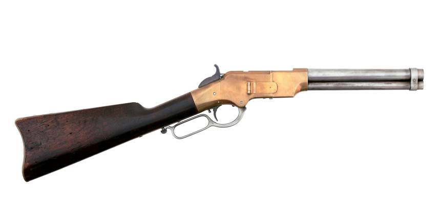
Left & right profiles of King’s prototype musket (Matthew Moss)
This developmental prototype is in the ‘musket’ configuration: with a longer barrel, a bayonet lug and a wooden forend. The prototype represents one of the many developmental steps towards what would become the Model 1866. It has a number of interesting features – a steel, rather than brass, receiver and a hinged loading port developed by Nelson King, Winchester’s superintendent between 1866 and 1875.
The rifle itself was built by Luke Wheelock, Winchester’s model room mechanic and a designer in his own right who would go onto develop his own rifle designs for Winchester.
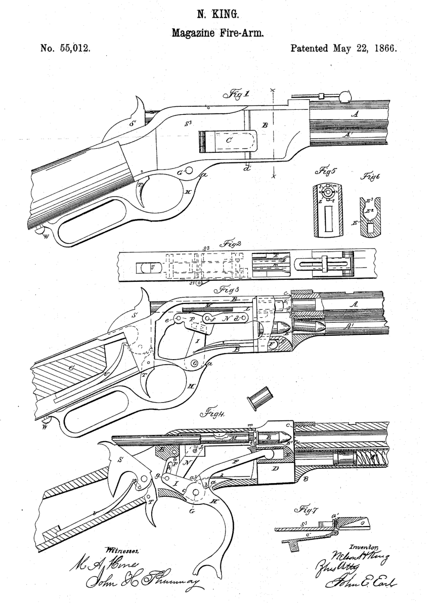
King’s 1866 patent (US Patent Office)
The rifle is 54.5 inches long, with a 33.75 inch barrel. Believed to have been built in 1866, it is chambered for a .45 calibre rimfire round. King patented his loading port in May 1866. He described how the port worked:
“Through one of the plates S (preferring that one upon the right-hand side) I form an opening, 0, as denoted by broken lines, Fig. 1, and also seen in section, Fig. 7. This opening is formed so as to communicate through the frame directly to the chamber E in the carrier block, as seen in Fig. 3. Through this opening, and while the carrier-block is down and all parts of the arm in a state of rest, insert the cartridges, point first, through the said opening in the plate S into the chamber E the second cartridge pressing the first into the magazine, and so on with each successive cartridge until the magazine is filled, or until the requisite number has been inserted therein, the follower G being pressed up before the entering cartridges. In the rear of the chamber E2 the frame forms a shoulder to prevent the cartridges from being forced out through the opening in the plate S3 is a cover for closing the opening in the plate S3 and is hinged thereto, as seen in Figs. 1 and 7, the hinge being provided with a spring,a1, the tendency of which is to open the cover C. A spring-catch, d, (see Fig. 1,) secures the cover when closed, so that by pressing upon the said catch the cover will fly open. After the requisite number of cartridges have been placed within the magazine, close the cover, as seen in Figs. 1 and 2.”
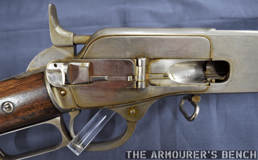
A close up of the hinged loading gate (Matthew Moss)
To paraphrase: ammunition can be loaded through the opening in one of the receiver side plate when the carrier block is down, insert the cartridges through the opening, pressing the first into the magazine and so on until the magazine is filled… a cover for closing the opening is hinged to the receiver side plate. A spring catch secures the cover when closed.
According to Herbert Houze, King developed the covered loading port design in early January 1866, with a design drawing dating to the 14th January, confirming this.
King altered the design of the rifle’s cartridge carrier so that a cartridge could pass through its lower section straight into the magazine when the action was closed. In theory the aperture could be placed on either side of the receiver, in practice is was placed on the right. Prior to this Winchester had experimented with systems where the tube could slide forward (G.W. Briggs US #58937), a port in the base of the receiver (J.D. Smith US #52934) or a sliding forearm covering a loading port at the rear of the magazine tube (O.F. Winchester UK #3284 [19/12/1865]).
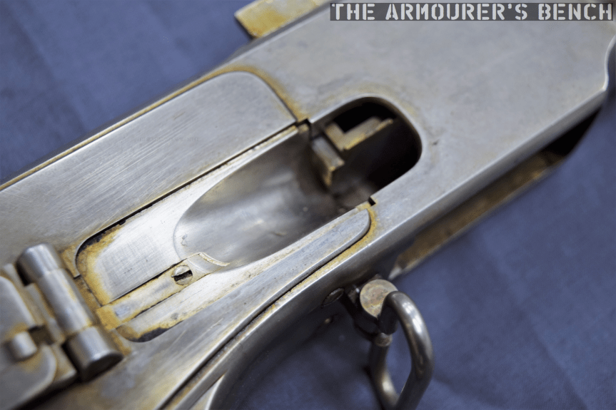
A look inside the hinged loading gate (Matthew Moss)
King’s system had the benefit of allowing the rifle to be quickly loaded or topped off without rendering the rifle unusable while loading. Positioning the port in the receiver allowed the magazine tube to be enclosed by a wooden forend.
A cartridge guide was fitted inside the receiver which guided rounds through the cartridge carrier and into the tube magazine. The rounds were prevented from popping out of the magazine, when the carrier was aligned and the cover open, by a shallow shoulder which projected in line with the carrier’s channel to hold cartridges in the tube by their rim.
The musket with its action open, bolt to the rear and loading gate open (Matthew Moss)
The hinged cover is held shut by a spring catch mounted on the rear of the cover. When the knurled section on its front is pressed rearwards the cover pops open. The spring catch is actuated when it tensions against the cover’s hinge as it is closed. On the back of the cover there is also a cartridge stop for when the cover is closed.
Another small but interesting feature of the prototype is the catch at the rear of the lever loop, this differs from the manually turned catch seen on the Henry and production 1866. This design appears to be a much better safety feature, simply requiring the user’s hand to depress the catch to unlock it from the stock. It also appears to be a much simpler mechanism than that seen in later models like the Model 1895. The trigger also had an extension protruding from its rear which appears to prevent the trigger from being pulled when the lever isn’t full closed. Neither of these features appear in King’s May 1866 patent.
It appears that the idea of the port with a hinged cover was superseded by what we now recognise as the classic Winchester loading gate in the summer of 1866. King’s new system replaced the hinged cover with a piece of stamped spring steel attached to the inside of the receiver side plate by a screw. The spring steel gate could be pushed in, with the nose of a cartridge, to allow rapid loading. The front face of the gate formed a cartridge guide removing the need for the separate machined guide used in King’s earlier iteration of the system.
(Rock Island Auction Company)
King’s revised loading port system required just five, rather than twelve, components: King’s altered cartridge carrier, receiver side plate, spring metal loading gate plate and retaining screws. This simple but elegant design continued to be used for decades on various models of rifle. The company were so pleased with the refinement of the rifle that, according to R.L. Wilson, King was awarded a payment of a $5,000 reward by the company’s board of directors.
Winchester introduced the rifle in 1866, with the first deliveries being made early in 1867, the new rifle was offered in various barrel lengths and patterns including carbine, rifle and ‘musket’. Winchester found some success selling 1866 rifles to the militaries of France and the Ottoman Empire, while many other countries purchased rifles for testing including Britain and Switzerland (whom came close to adopting the Winchester.) The rifles also found success on the civilian market with around 4,500 sold in the first five months.
Right side profile of the rifle showing the hinged loading gate (Matthew Moss)
The Scientific American described the new rifles as “elegant in appearance, compact, strong, and of excellent workmanship. On examination we find its working parts very simple, and not apparently liable to derangement.”
King incrementally developed his loading system before radically simplifying it and this prototype rifle represents an important developmental step in the design of what would become the Model 1866 – one of Winchester’s most important rifles.
Special thanks to the Cody Firearms Museum for allowing us to take a look at this fascinating prototype rifle.
If you enjoyed this article and video please consider supporting our work here. We have some great perks available for Patreon Supporters. You can also support usvia one-time donations here.
Bibliography:
Winchester Repeating Arms Company, H. Houze (1994)
Winchester: An American Legend, R. L. Wilson (1991)
During the Second World War Britain’s Special Operations Executive (SOE) developed a whole series of sabotage devices for use behind enemy lines. Using unique archival footage this series of short videos examines some of the weapons developed for use by SOE agents in occupied Europe. In this episode we look at an explosive magnet bomb, designed to be attached to any magnetic surface and detonate to destroy machinery or vehicles. It later evolved into the small pocket-sized ‘Clam mine’.
Today, we’re lucky enough to have some colour footage showing the of testing of a magnetic bomb which could be attached to the petrol tank of vehicles. The footage comes courtesy of the Imperial War Museum.
A still from the footage showing the charge placed on the body of the car (Imperial War Museum)
From the film we can see that the bomb consisted of a small block of plastic explosive, a pair of strip magnets (or possible a horseshoe-shaped magnet) and a Switch No.10 time pencil delay detonator. The explosive block itself looks to be slightly smaller than the SOE’s standard 1.5lb charge.
In the film we see the bomb placed on the boot (or trunk) of a saloon car before various civilians and a corporal experiment with various ways of covertly attaching the bomb to the underside of the car. At one point the corporal allows himself to be dragged along behind the vehicle before making his escape.
Luckily the 16mm footage, filmed by Major Cecil Clarke, also shows us the effect of the explosive charge mounted on a petrol tank full of fuel. According to the details listed for the film by the Imperial War Museum the footage was filmed in 1940, at SOE Station XVII, located at Brickendonbury House in Hertfordshire.
A still from the footage showing the bomb’s magnets (Imperial War Museum)
This configuration of the bomb doesn’t appear in the Special Operations Executive’s Descriptive Catalogue of Special Devices and Supplies published in 1944. However, Colonel Leslie Wood, Station XII’s commanding officer, described the demonstration put on during a visit by Brigadier Robert Laycock of the Commandos and William Donovan, the head of the American OSS in June 1942. One of the scheduled demonstrations was the “Effect of small ‘magnet’ charge of explosive on petrol tank of car.”
It appears that this ad hoc magnet charge evolved into ‘the Clam’, which was a smaller, version of the magnetic Limpet mine. The Clam evolved through a number of marks with the MkI having a stamped sheet metal casing and the later MkIII using a bakelite, plastic casing. Both were made up of a plastic explosive charge inside a rectangular, rounded case with a pair of magnets at either end. They were detonated by either a Time Pencil or an L Delay fuse attached to a No.27 detonator. The MkIII had 8oz (226g) of high explosive filler, such as TNT/Tetryl 55/45.
MkIII Clam (Imperial War Museum)
While unlike the larger Limpet they weren’t developed for under water use but the Clam could be mount onto any vaguely flat magnetic surface including engine blocks, fuel tanks, crank cases, cylinder blocks, rail tracks and steel plate.
At just 5.75” x 2.75” x 1.5” they were easily concealable, could be carried in a pocket and were non-descript enough not to draw attention. An estimated 68,000 Clams were made under supervision at Aston House according to Des Turner’s book on Station XII.
We’re lucky enough to have some unique colour footage showing the of testing of some of these explosive devices and in this article we will examine an incendiary-filed case.
In this piece of 16mm colour footage, filmed in 1940 by Captain Cecil V. Clarke, we see what appears to be an attaché case containing three medium-sized bottles, which likely contains a mix of petrol and paraffin or some white phosphorus, prepared for testing at the bomb range at Brickendonbury in Hertfordshire, a Special Operations Executive training and research centre codenamed Station XVII. It’s believed that these films may have been produced as teaching aids for the agents trained at Station XVII and this film may have been shown during a lecture.
A still from the footage showing the case being set up at the test range (IWM)
While incendiary briefcases, attaché cases and even suitcases are listed in the 1944 SOE Descriptive Catalogue of Special Devices and Supplies they were quite different from this case. They were primarily designed for the quick destruction of documents and items carried inside them. They used sheets of potassium nitrate to burn the case’s contents.
The incendiary case seen in this footage on the other hand appears to be designed to be clandestinely placed and detonated with a delay fuse, to set nearby flammable objects on fire. What was described as a ‘Delayed Action Incendiary’.
The Incendiary Suitcase entry from the SOE’s Descriptive Catalogue of Special Devices and Supplies
In this footage of another separate test we get an idea of the destructive capability of just one of the bottles.
It’s possible that this incendiary case was a proof of concept test for the later cases or perhaps a demonstration of a concealed incendiary device Station XVII were working on. SOE developed a large number of bespoke explosive devices for various missions, so while this device may not have become ‘standard issue’, it may have been developed for a specific purpose.