Today we have a bit of an interesting unpacking/unwrapping video. I’ve saved up a few parcels with some new additions to the TAB reference collection and I thought I’d bring you along for the ride. The manuals we’ll be taking a look at span about 60 years of British Army doctrine and weapons. The materials range from a Hotchkiss machine gun manual from 1917 to an AFV identification handbook from the late 60s. There’s some quite interesting and rare stuff here including a 1951 provisional manual for the 3.5in rocket launcher.
These manuals and this sort of primary material is really important because we can learn how the weapons were actually intended to be used. It’s support from our Patreon supporters that enables us to pick up items like these to share in videos. So if you’d like to support our work, check out the TAB Patreon page here.
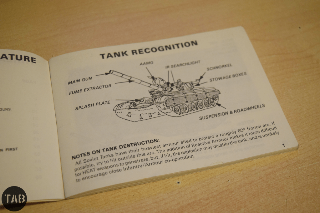
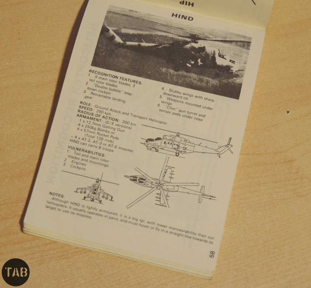
It’s the 1980s and the British Army Of the Rhine is still stationed in West Germany facing down the USSR’s forces. The Cold War has gotten hot and the 3rd Shock Army is approaching your dugout but how do you differentiate a BTR from a BMP? This handy British Army THREAT Recognition Guide booklet gives you everything you need to know about the Soviet armour, infantry and aircraft you’re facing!
Continuing on from our earlier look at a British Army threat Recognition Guide to Iraqi Ground Forces issued during the Gulf War, we dig into the TAB reference collection again and take a look at this Threat Recognition Guide looking at Soviet air and ground forces facing the British Army of the Rhine in the 1980s.
The Group of Soviet Forces in Germany (GSFG) in East Germany throughout the Cold War were an ever present threat to West Germany and NATO. This recognition guide covers all of the USSR’s main battle tanks, armoured personnel carriers, and infantry fighting vehicles, as well as artillery systems and some of the close support aircraft which would have accompanied the attacking Soviet forces.
The pages of the recognition guide include photographs, diagrams, basic specs and recognisable features of the various enemy vehicles. It was put together by the Intelligence Directorate of BAOR’s 1 Corps.
If you enjoyed these videos and this article please consider supporting our work here. We have some great perks available for Patreon Supporters. You can also support us via one-time donations here.Thank you for your support!
I’m very excited to say that my second book has been published! It looks at the much maligned and much misunderstood PIAT – Projector, Infantry, Anti-Tank.
The book is available from retailers from the 20th August in the UK/Europe and the 22nd September in the US – but you can order a copy from me now regardless of location. I filmed a short video to show you the book and talk a bit about the process of writing it, check that out above.
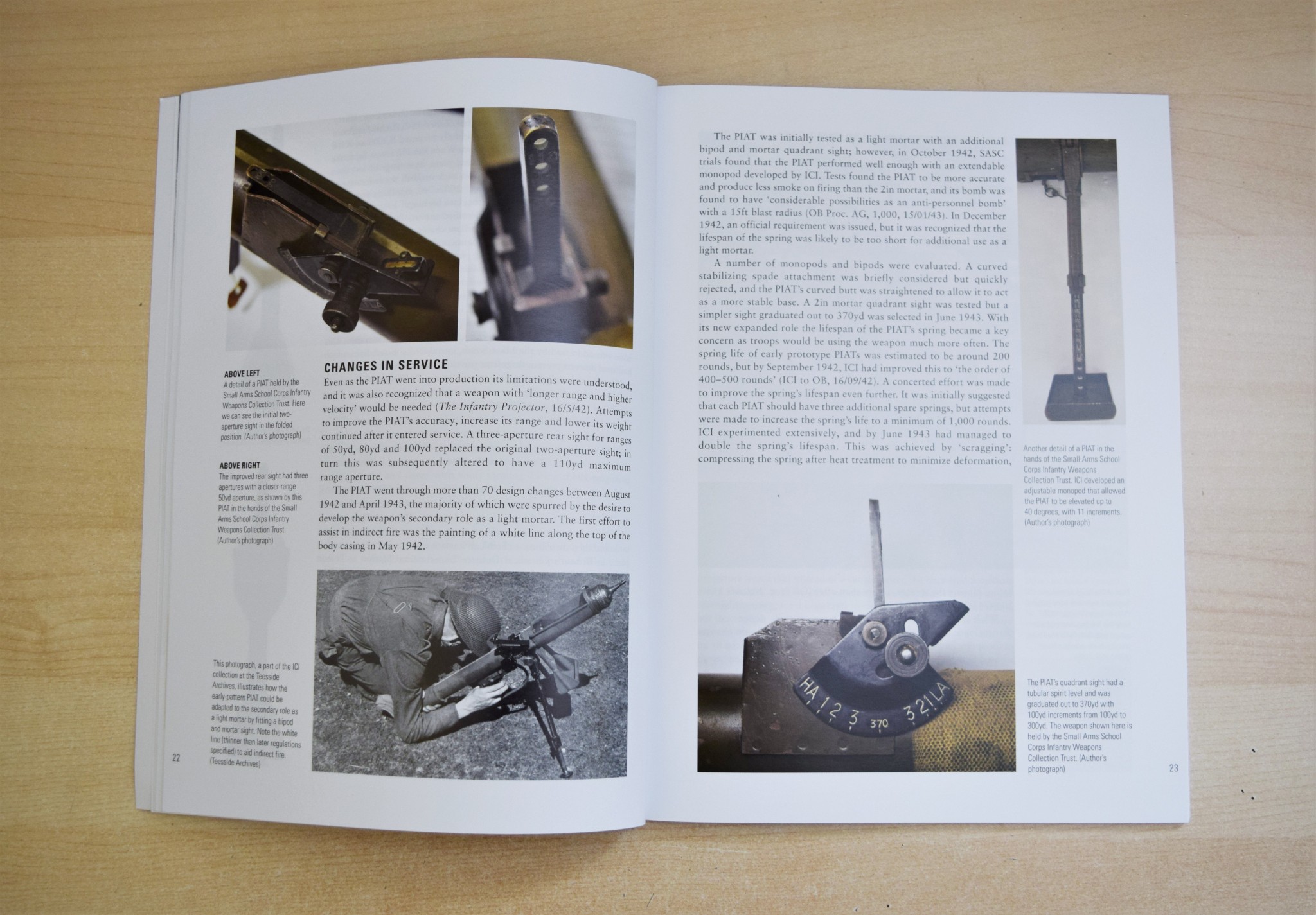
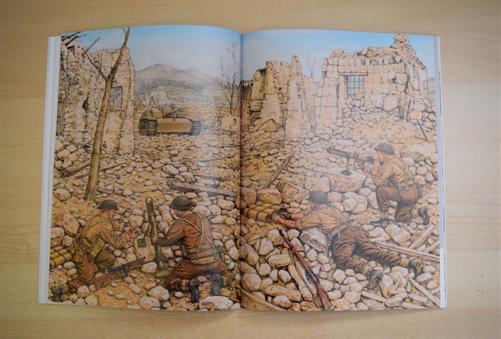
The PIAT was the British infantry’s primary anti-tank weapon of the second half of the Second World War. Unlike the better known US Bazooka the PIAT wasn’t a rocket launcher – it was a spigot mortar. Throwing a 2.5lb bomb, containing a shaped charge capable of penetrating up to 4 inches of armour. Thrown from the spigot by a propellant charge in the base of the bomb, it used a powerful spring to soak up the weapon’s heavy recoil and power its action.
With a limited range the PIAT’s users had to be incredibly brave. This becomes immediately obvious when we see just how many Victoria Crosses, Military Medals and Distinguished Conduct Medals were awarded to men who used the PIAT in action.
The book includes numerous accounts of how the PIAT was used and how explores just how effective it was. I have spent the past 18 months researching and writing the book and it is great to finally see a copy in person and know it’s now available.
The book includes brand new information dug up from in-depth archival research, never before seen photographs of the PIAT in development and in-service history and it also includes some gorgeous illustrations by Adam Hook and an informative cutaway graphic by Alan Gilliland.
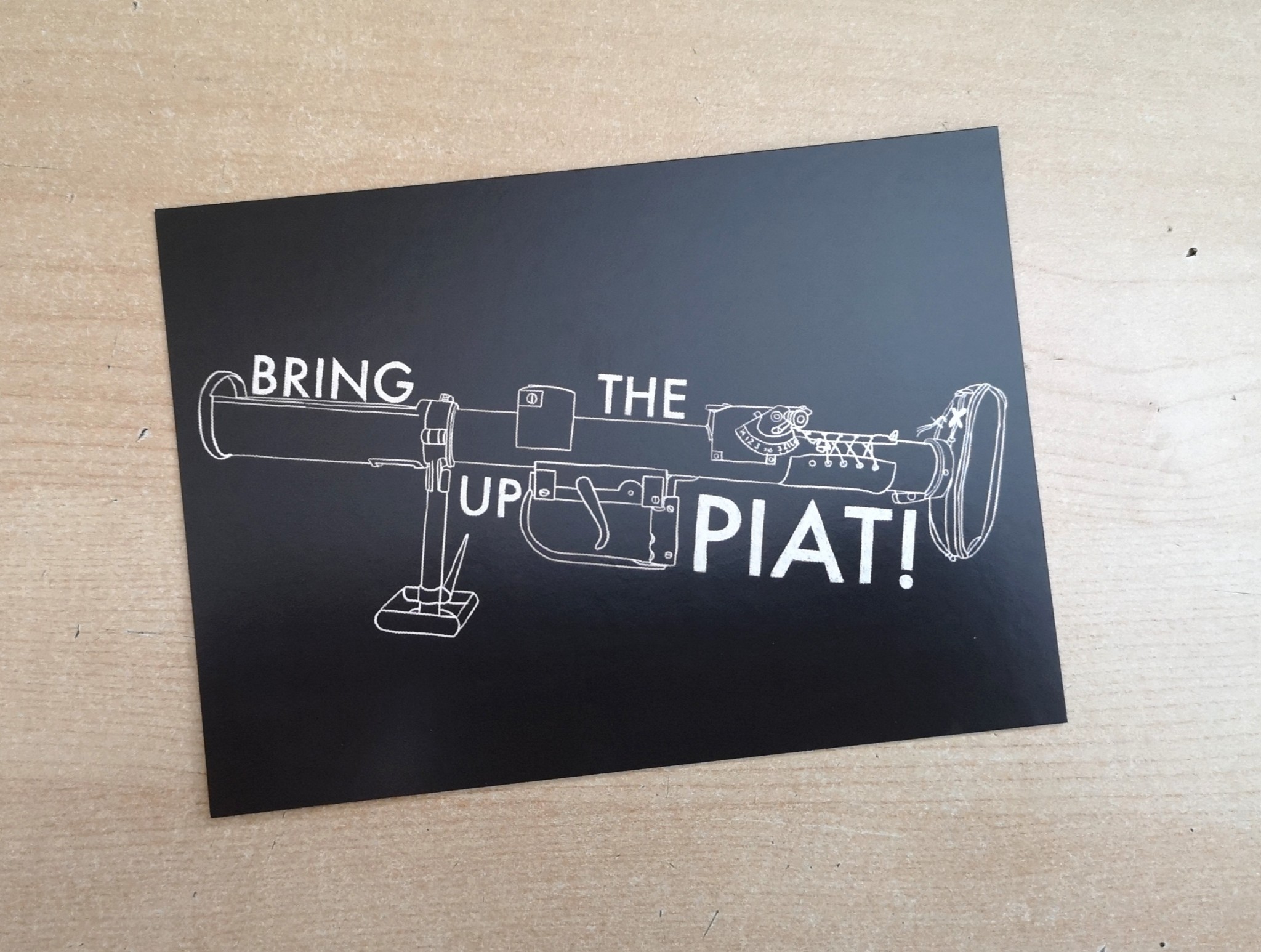
If you order a book directly from me I’ll also include this custom illustrated postcard with a design featuring a PIAT and the famous line from A Bridge Too Far.
It’s immensely exciting to know the book is out in the world for all too enjoy. If you’d like a copy of my new book looking at the PIAT’s design, development and operational history you can order one directly from me here!
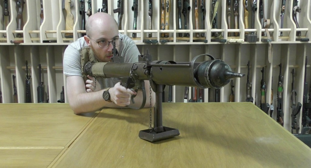
Me, bringing up the PIAT…
Thanks for your support and if you pick up a copy of the book I really hope you enjoy it!
Sometimes all is not as it seems. That was the case when we examined this Steyr AUG. From the barrel and bipod it appeared to be an AUG in an HBAR or Heavy Barrel configuration but on closer inspection we found that it was in fact a rifle receiver, bolt and bolt assembly and chassis that had been paired with an HBAR barrel assembly.
Vic with the Steyr ‘HBAR’ (Vic Tuff)
Ordinarily, the HBAR could be modified to fire from an open, rather than closed, bolt. This example has the standard AUG progressive trigger for semi and full-auto. It does not have the modified bolt carrier, striker or trigger mechanism.
The HBAR has a 4x optic, rather than the rifle’s 1x, while the HBAR-T can be fitted with an optic like a Kahles ZF69 6×42.
A dedicated ‘LMG’ marked AUG stock and bolt carrier (Vic Tuff)
Adoption of the AUG HBAR does not appear to have been widespread and Steyr don’t currently list it as an option amongst their upgraded AUGs. For more Steyr we have previously examined a Steyr AUG SMG conversion and a Steyr MPi 81. We’ll take an in depth look at the AUG and AUG HBAR in the future.
Overall Length: 35.5in (90cm)
Barrel Length: 24.4in (62cm)
Weight: 8.6lb (3.9kg)
Action: Gas operated, rotating bolt – the HBAR typically fires from an open bolt, but this rifle-based example fires from a closed bolt.
Capacity: 30 or 42-round box magazines
Calibre: 5.56×45mm
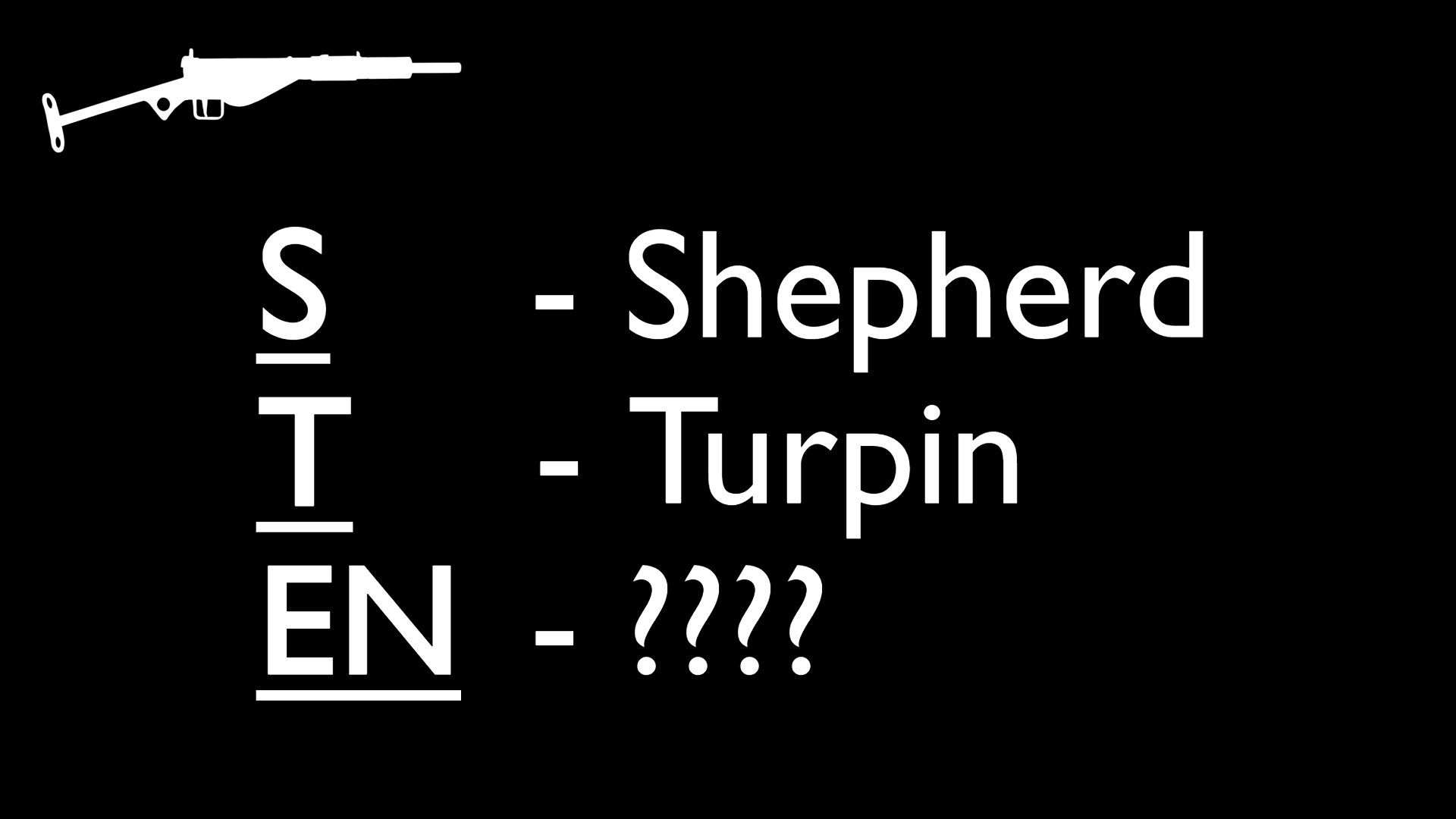
The Sten is one of Britain’s iconic Second World War Small arms. Two men are principally responsible for its development Colonel Reginal Vernon Shepherd and Mr. Harold John Turpin a pair of small arms and engineering experts with considerable experience.
Turpin was born in Kent in 1893, served his apprenticeship as a draughtsman in Erith and in 1922, he joined the drawing office at the Royal Small Arms Factory Enfield – Britain’s principal state small arms centre.
British Army manual illustration
Reginald Shepherd was born in 1892, received an Bachelor of Science Degree from Leeds University in 1912. In October 1914, he joined the West Yorkshire Regiment as a second lieutenant, serving in Gallipoli and Egypt. After the war, with his engineering background, he assigned as 2nd Assistant Superintendent at the Design Department at RSAF Enfield in December 1922, and promoted to captain.
The two men found themselves joining Enfield at around the same time. In November 1933, Shepherd, now a major, was appointed Inspector of Small-Arms (Class 2) at Enfield and assisted in getting the Bren light machine gun into service. He remained at Enfield until 1936, when he retired from the army and spent a short spell at BSA before being recalled. In late 1939, Major Shepherd returned to active service and once again took up the position of Inspector of Armaments, this time at the Ministry of Supply Design Department at Woolwich Arsenal.
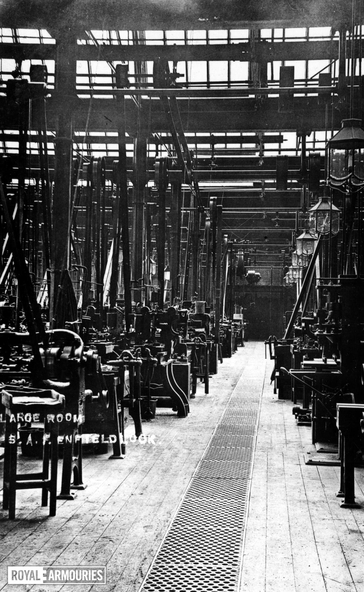
Inside RSAF Enfield (Royal Armouries)
By the outbreak of the Second World War Turpin had become the senior draughtsman at Enfield and when the development of the Lanchester Machine Carbine began he was paired with Major Shepherd to draw up technical drawings for the gun’s production.
The two men decided that a simpler, cheaper submachine gun could be produced and in December 1940 set about designing it, with Turpin in the lead. During the Winter of 1940-41 the first prototypes were built. Development of the first Sten – the T40, was completed on 8th January 1941, taking just 36 days.
14 pilot models were ordered but only two were completed by engineers at the Philco Radio Works in Middlesex: T-40/1 and T-40/2. The gun was initially designated the ‘T-40’ or Turpin, 1940. By the end of January 1941, it had become known as the ‘ST Machine Carbine’. The ‘Carbine, Machine, STEN, MkI’ was approved for issue on 7th March, 1941, with 100,000 guns ordered.
How did the gun become known as the ‘STEN’ and what did Sten stand for?
We know that the ‘S’ stands for Shepherd and the ‘T’ for Turpin, but what about the ‘EN’ – it is generally accepted to represent ‘Enfield’. Why? Because RSAF Enfield is synonymous with British military firearms. Additionally the Bren light machine gun’s name is a portmanteau of ‘BR’ from Brno, the location of the Czech factory the zb.26/30 originated from, and ‘EN’ for Enfield, the British factory that anglicised the design for British manufacture and service.
Enfield, however, wasn’t where the Sten was designed. Turpin and Shepherd claimed that most of the work on the design had been done out of hours. Additionally, during the winter of 1940, the Armament Design Department was relocated, from Enfield to a former Drill Hall in Cheshunt, Hertfordshire to escape the bombing of London.
While the Sten may not have been designed at Enfield, the first prototype was partially assembled there with work also done at Turpin’s own home workshop. A further 46 pre-production pilot models were later ordered from RSAF Enfield, in February 1941.
Intriguingly, early accounts suggest that ‘EN’ may have stood for ‘England’ – not ‘Enfield’. In October 1942, the fifth instalment of ‘Know Your Weapons’, a semi-official series of weapons manuals printed by the publisher Nicholson & Watson, explains that ‘EN’ did in fact stand for ‘England’.
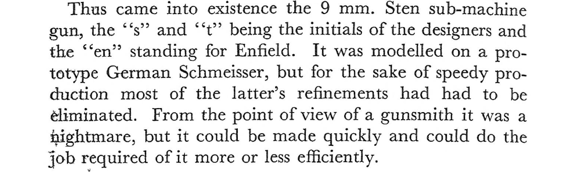
In June 1943, Turpin penned a semi-anonymous article for ‘The Model Engineer’, about the design and development of the gun, which repeated this claim. An October 1943, article in the US Popular Mechanics magazine, entitled ‘Machine Guns from Backyard’, includes a supposed quote from the inventors explaining that the “E and N stood for England.”
‘The Sten Carbine’, Model Engineer, Turpin, June 1943
A more official account came in June 1949, at a hearing of the Board of the Royal Commission Awards to Inventors (a board set up to reward inventors who had done important war work). One of the board members Lord Justice Sir Lionel Cohen asked Shepherd: “Why was it called the Sten?” The colonel replied: “It was called the Sten by the then Director General of Artillery. The ‘S’ was from my name, the ‘T’ from Mr. Turpin, who was my draughtsman and who did a very large amount of the design, and the ‘EN’ was for England. That is the origin of the name, for which I accept no responsibility.” This suggests that the ‘EN’ standing for ‘England’ may have originated from the upper echelons.
Sadly, there was no officially published explanation of the name as official manuals rarely go into superfluous detail. In 1948, however, Ian Hay published R.O.F. The story of the Royal Ordnance Factories, 1939-1948 in which he stated the ‘EN’ was a reference to the Enfield factory. Similarly, another early published account, D.M. Ward’s 1946 The Other Battle, a history of BSA, also suggested it represented the factory name.
In truth it is difficult to know exactly what the ‘EN’ stood for. It may be that both Enfield and England were discussed and used by various individuals and offices. There may have been an element of propaganda to including ‘England’ in a weapon’s name which led senior officers to push this in the press and direct the gun’s inventors to suggest this was the case too. Of course the authors of those earlier books may have mistakenly believed ‘EN’ stood for Enfield, as it does in Bren. Personally, I’m inclined to follow the primary sources attributed to the two men responsible for the design, and believe it initially stood for England.
The Other Battle, D.M. Ward, (1946)
Shepherd was awarded an OBE in January 1942, and became the Assistant Chief Engineer Armament Design (A/CEAD), he was promoted to Lt. Colonel in August 1943. He retired from active duty at the age of 55, in January 1947, and was removed from the reserve list. He was granted the honourary rank of colonel. He died in April 1950, aged 58. Turpin retired from RSAF Enfield in 1953, and died in April 1967, aged 74.
Beyond a pair of discretionary payments, £1,500 to Shepherd and a small payment of £200 to Turpin, neither man was officially rewarded as they were deemed to have essentially done what they were paid for, designing small arms. Scant reward and recognition for a weapon which became one of the key wartime small arms of the British and Commonwealth forces.
Our thanks also to Jonathan Ferguson, of the Royal Armouries, for sharing his thoughts on the ‘Enfield’ vs ‘England’ debate.
Bibliography
The Sten Machine Carbine, P. Laidler, (2000) R.O.F. – The Story of the Royal Ordnance Factories, 1939-1948, I. Hay, (1949) The Other Battle, D.M. Ward, (1946) The Sterling Submachine Gun, M.J. Moss, (2018) The Sten Gun, L. Thompson, (2012)
‘Sten & Bren Guns’, Know Your Weapon #5, (Oct. 1942)
‘The Sten Carbine’, Model Engineer, 3 Jun. 1943, H.J. Turpin Board of the Royal Commission Awards to Inventors – 1946-49
‘Machine Guns From Backyard’, Popular Mechanics, Oct. 1943
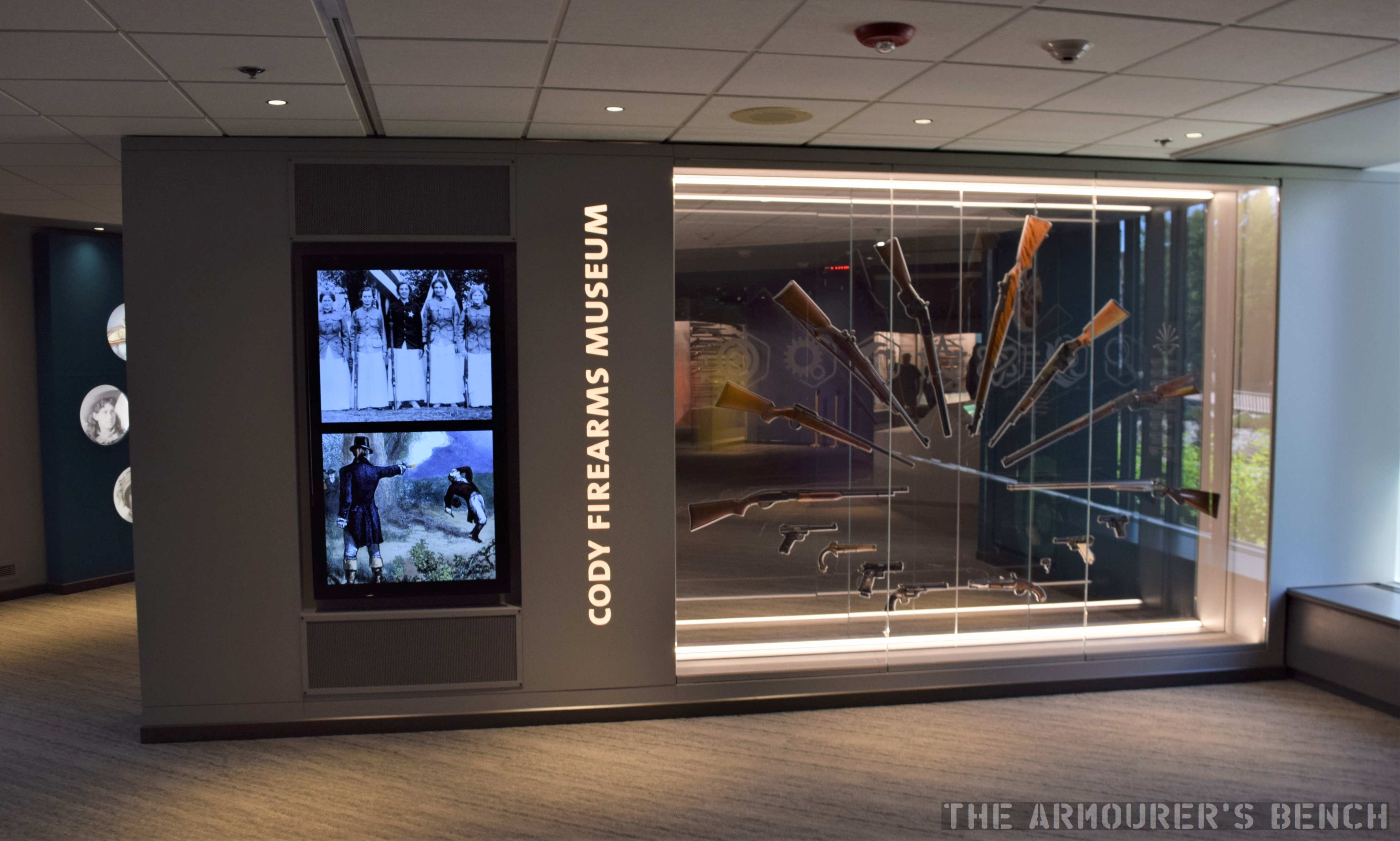
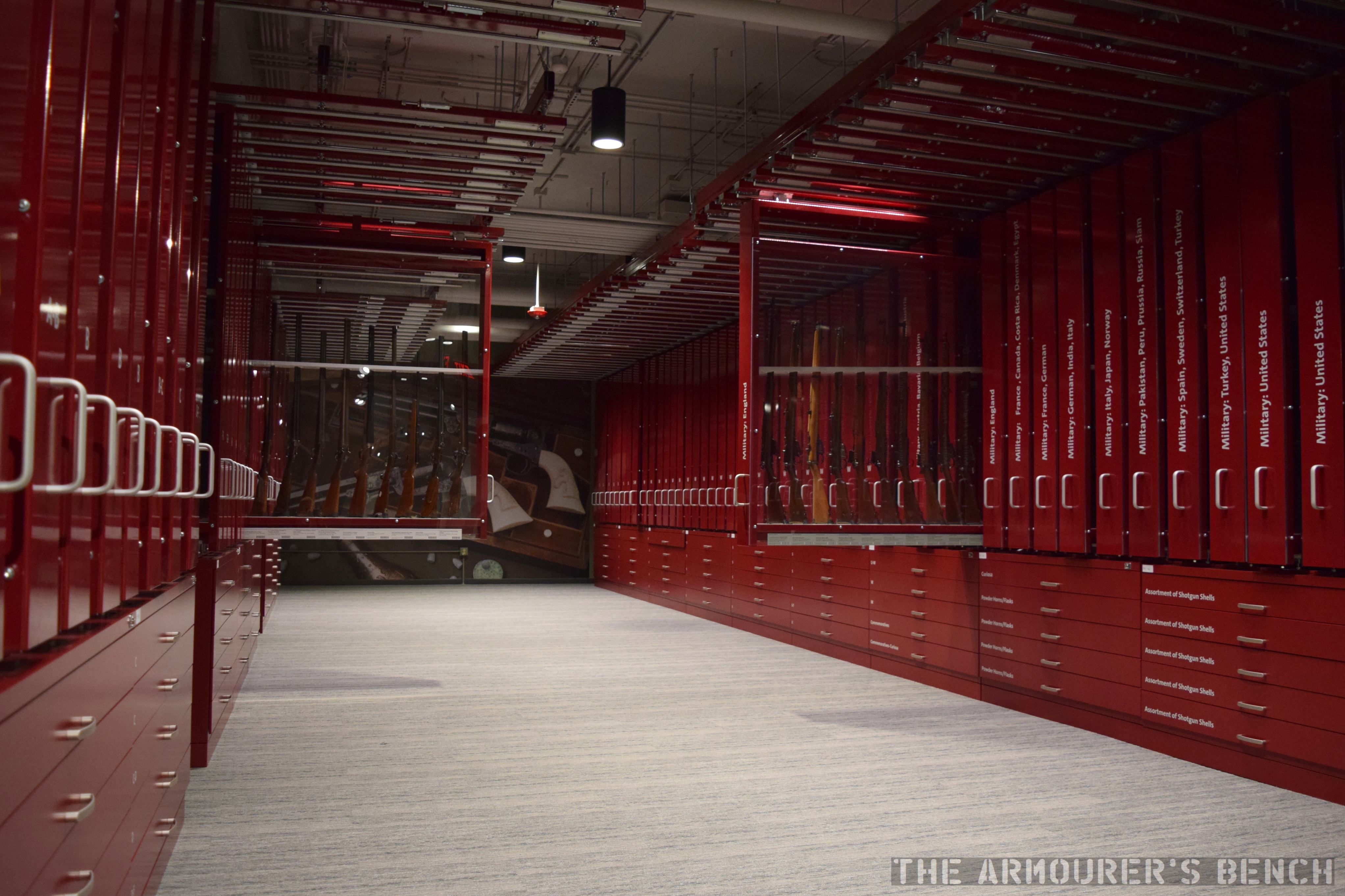
Last summer I had the chance to visit the newly renovated Cody Firearms Museum. With the ongoing Coronavirus Pandemic I thought now was a good time to finish my walk-around video taking a look at the new museum.
The museum has always had an extremely impressive collection of firearms and gun related artefacts, some of which we’ve been lucky enough to feature in videos, but the new museum puts more of these amazing firearms on display than ever before.
The CFM’s new and improved ‘gun fan’ (Matthew Moss)
The $12 million renovation has also allowed the museum to become much more interactive too with working models, touch screens and shooting simulators.
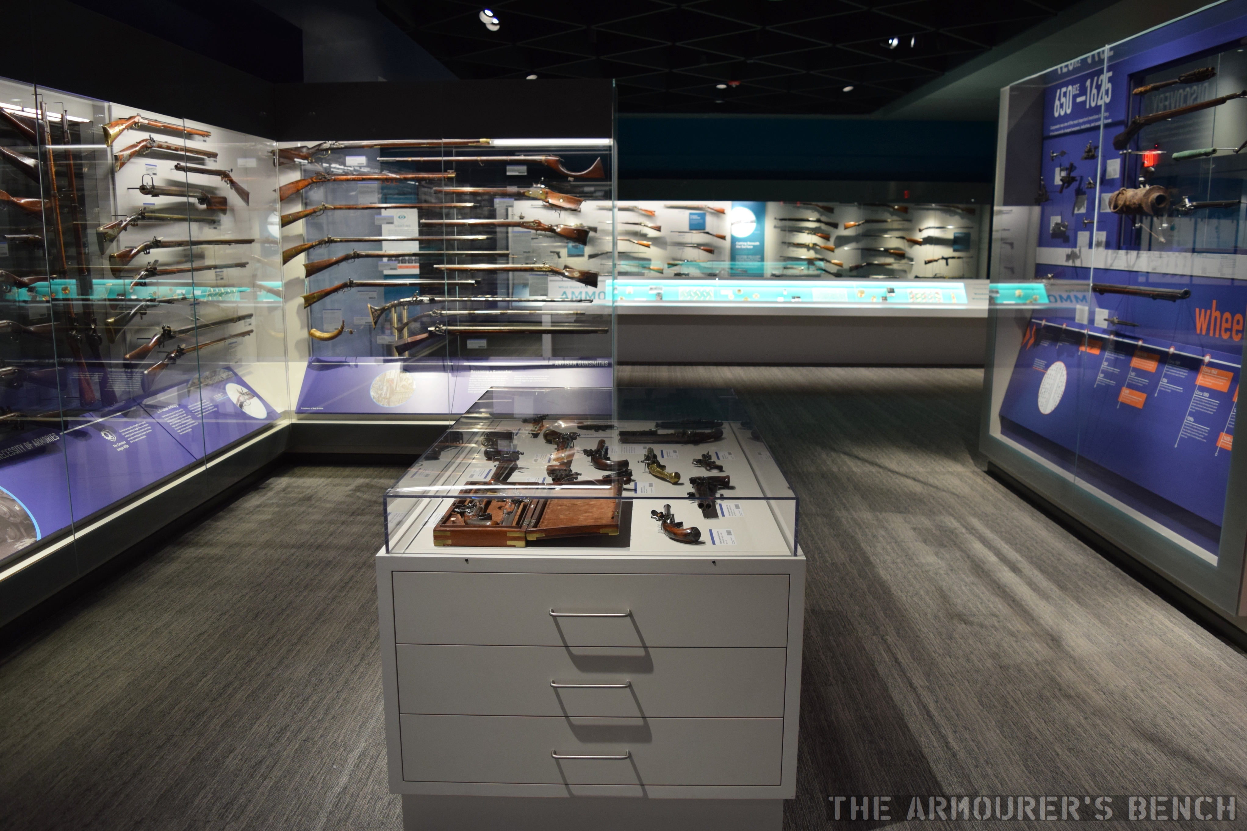
A view back through the first main gallery (Matthew Moss)
A new intuitive layout lets you explore firearm history either by chronology or by theme. In the photo above we can see some of the displays in the chronological gallery that shows the evolution of civilian and military firearms from their invention to the present.
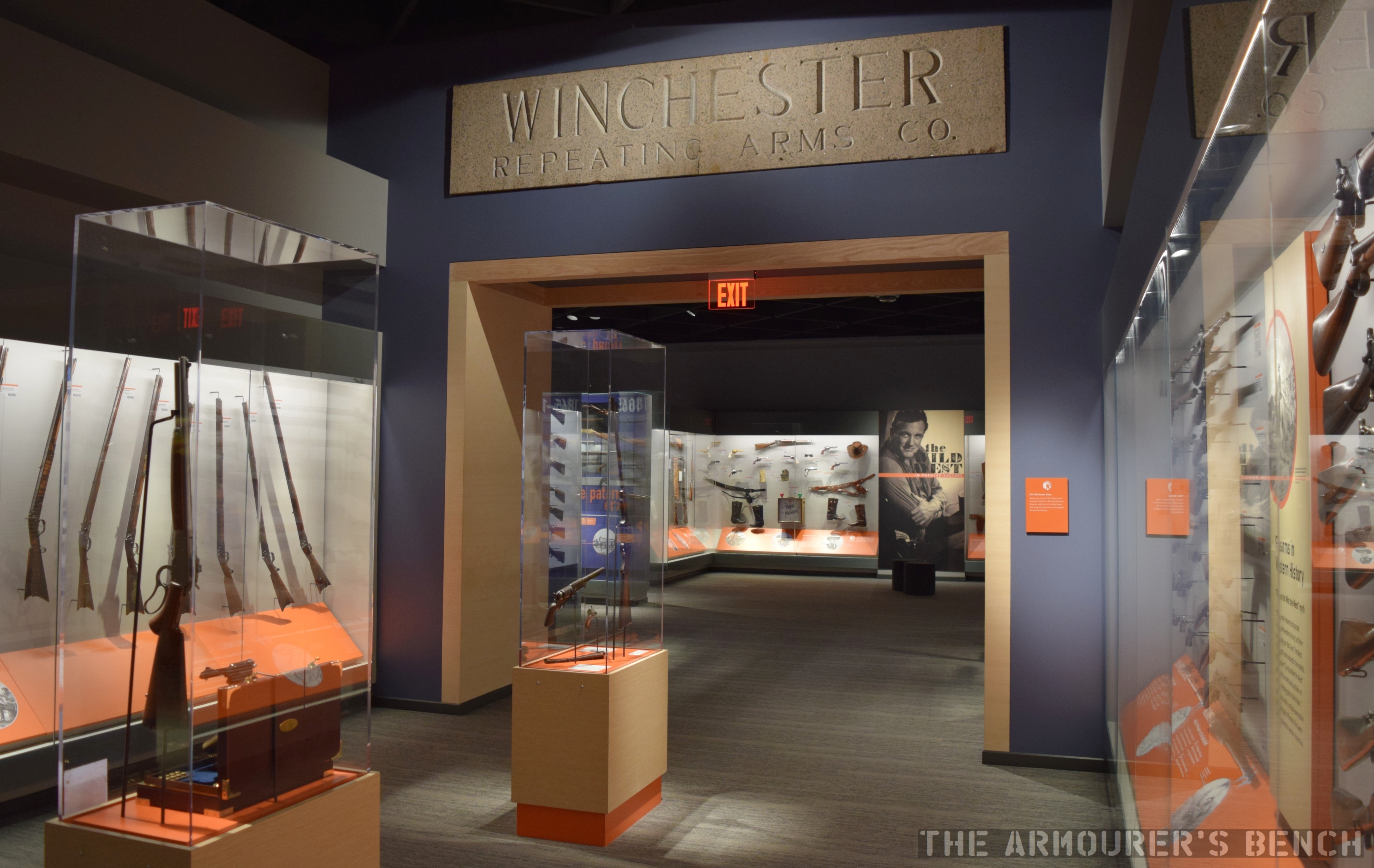
Some of the weapons of the West on display along with the original Winchester factory name stone (Matthew Moss)
One of the features I really liked was that many of the cases can be viewed on both sides allowing you to see all around the firearms.
Around the exhibits are touch screens where you can call up more information, first hand war stories and even animations of how various firearms work.
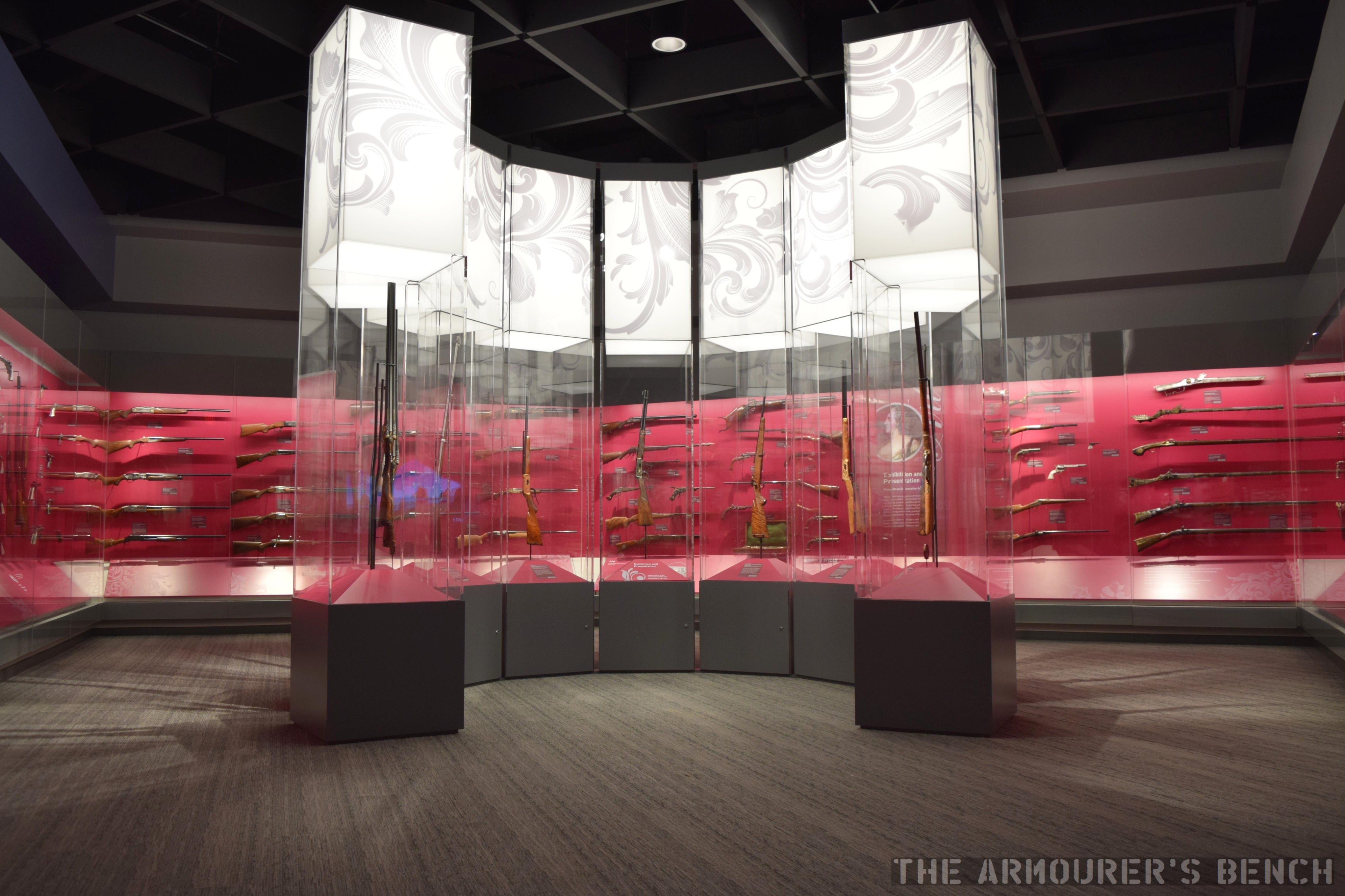
A gallery full of beautifully engraved firearms including some presidential presentation pistols (Matthew Moss)
There is also a gallery of ornately decorated firearms which includes some incredible pieces.
A detail shot from the military gallery (Matthew Moss)
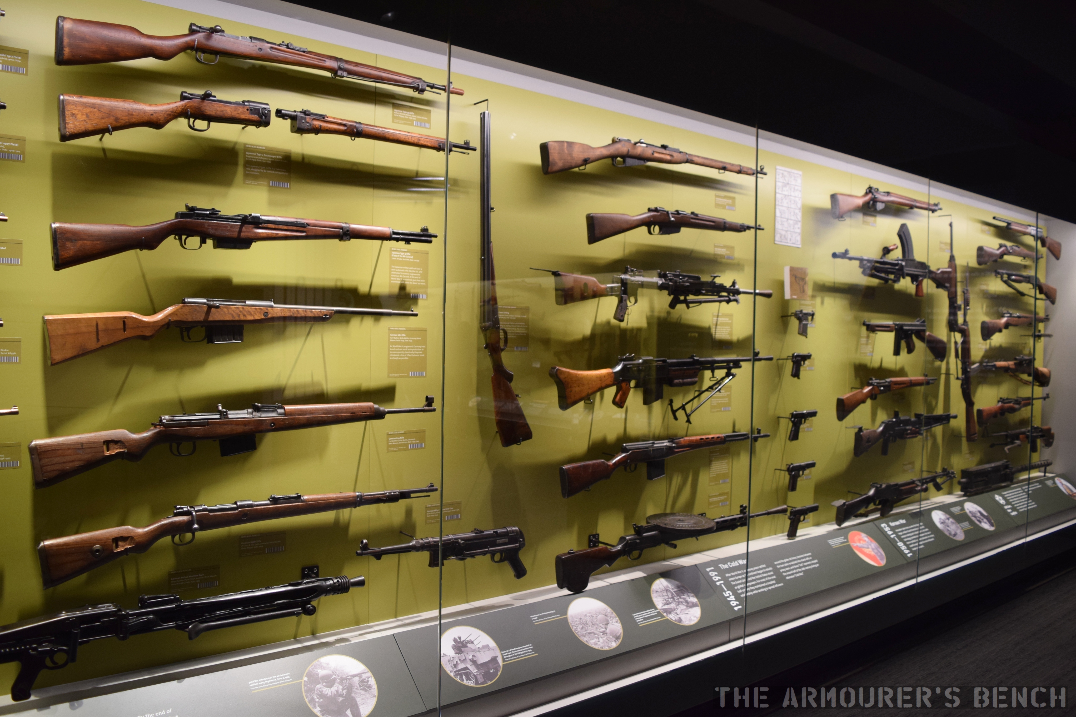
Unsurprisingly, the military gallery was one of my favourite parts of the museum with dozens of guns organised by conflict and period.
One of the cases in the military gallery (Matthew Moss)
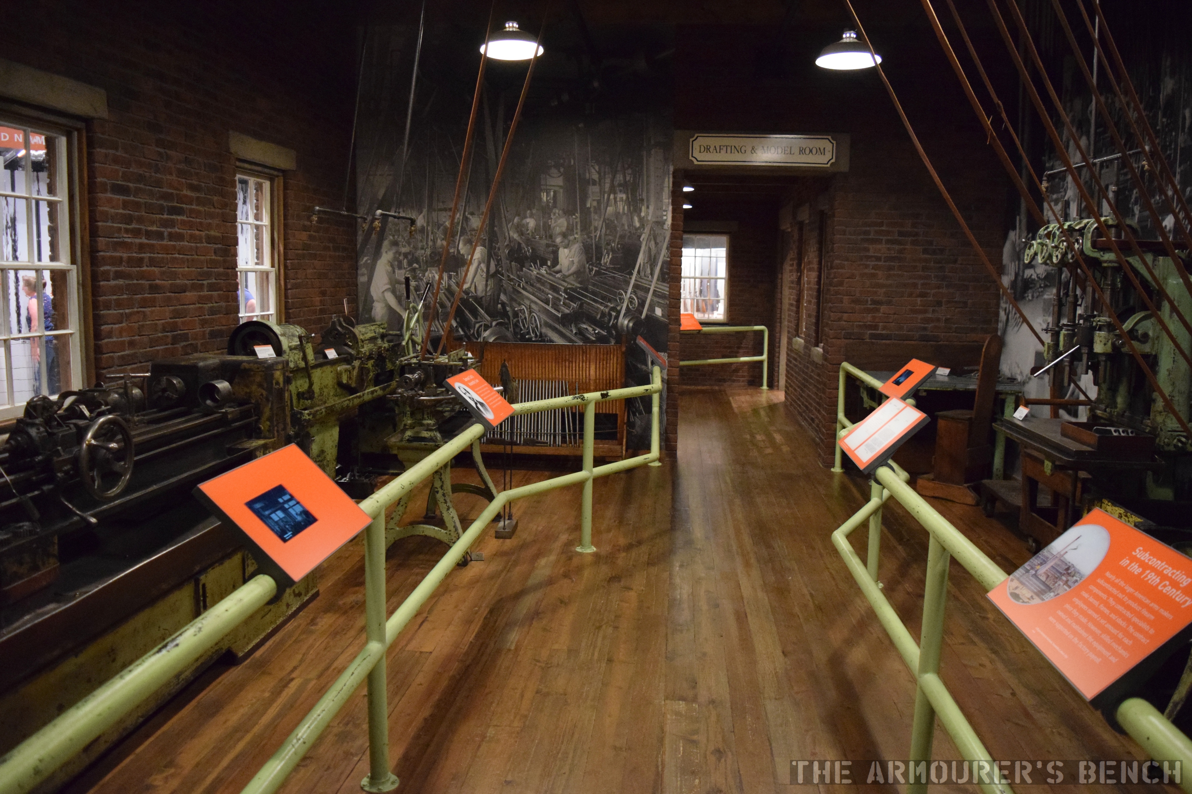
A look back through the recreated machine shop (Matthew Moss)
One of the best features of the original museum has also been retained, a recreation of a gun factory’s drafting room and machine shop.
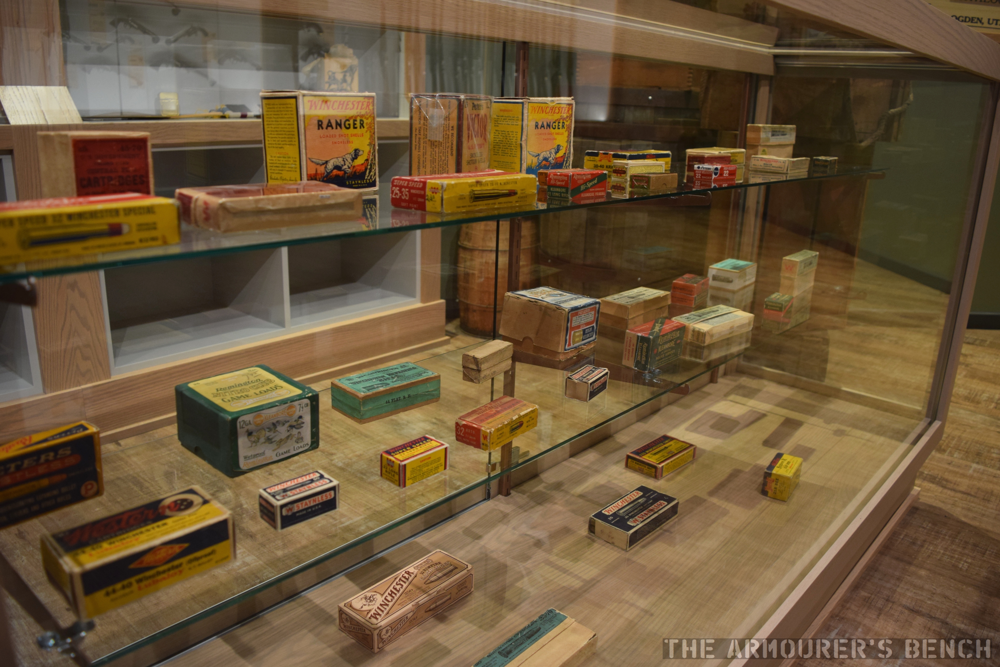
A detail shot of some of the ammunition packaging on display in the ‘general store’ (Matthew Moss)
One of the most interesting little sections is a recreation of a general store showing off some of the items that companies like Winchester made alongside their well known firearms.
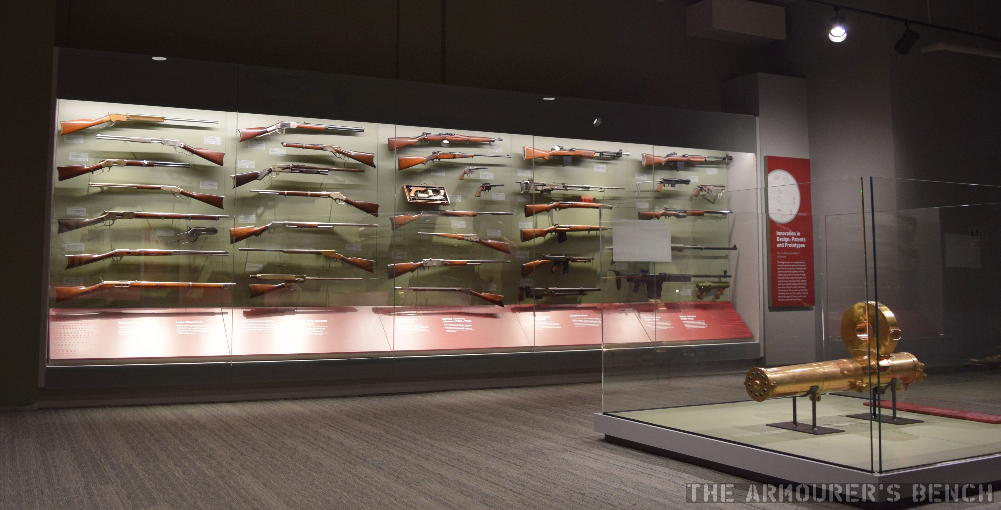
A case dedicated to experimental prototypes with the Gatling used in the initial development of the Vulcan in the foreground (Matthew Moss)
Downstairs is a space dedicated to experimental prototypes and a rolling wall of cases that include examples of hundreds of types of firearms and ammunition.
Some of the rolling cases open in the hall dedicated to showing off as many firearms as possible (Matthew Moss)
The newly refurbished museum puts the collection front and centre in a way that will enthral the average museum-goer and satisfy any avid gun enthusiast.
You can find out more about the museum here and check out some of the firearms we have had the privilege of examining from the CFM’s collection here.
This is the last of our series of videos/articles on the US Tanks of WWI, you can find all episodes here.
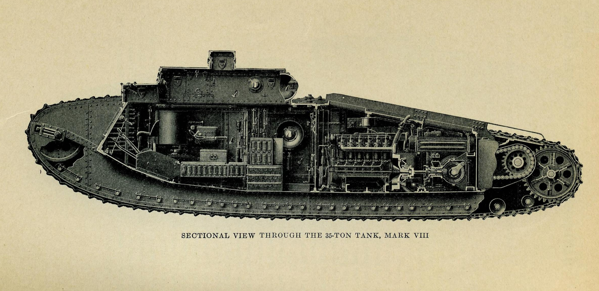
The MkVIII Heavy Tank holds the distinction of being the result of the first successful international co-operative tank project. Developed with input from British and American designers and engineers, intended to be equipped with British weapons and an American engine, with parts made in the US and Britain and to be assembled in France – a truly international undertaking. The MkVIII, sometimes referred to as ‘The International’ or ‘Liberty Tank’, owed its basic design to earlier British heavy tanks but a number of important changes were made.
Port side of a MK VIII heavy tank (US National Archives)
Intended for introduction in 1919, the war ended before the MkVIII could enter service and even before its French factory had been completed. It did, however, see some production and inter-war service providing the heavy tank backbone of the US’ tank force for many years.
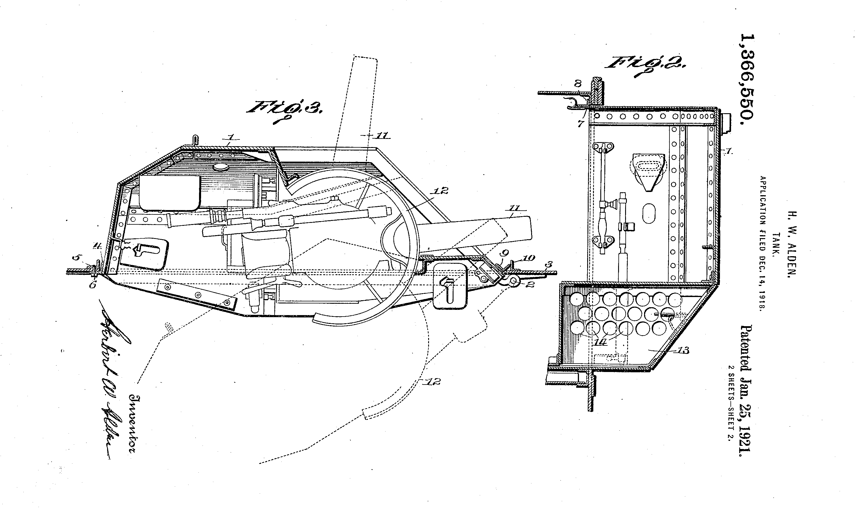
The design evolved from work by British Lieutenant G.J Rackham with later input from American engineer Major Herbert Alden. The MkVIII heavy was very much an evolution of the earlier British rhomboid heavy tanks but Rackham and Alden made some important improvements. Chiefly the redesigning of the tank’s sponsons which housed a pair of British 6pdr guns. While the tank was a foot narrower than its predecessors, the new folding sponsons could enabled the tank to be transported more easily by rail and to also, in theory, navigate narrow spaces. Alden patented this feature in December 1918 (US #1366550). Additionally, the commander’s ‘outlook turret’ positioned on top of the tank’s turret, which had vision slits on all four sides, was also retractable. Alden’s sponsons were hinged at the front and mounted on rolling bearings so they could pivot inwards.
Alden’s patent for his pivoting sponson (US Patent Office)
The MkVIII directly addressed several shortcomings of earlier British heavy tanks, firstly the engine was insulated in its own compartment to prevent exhaust fumes overwhelming the crew. A new ventilation system was also added with a fan keeping fumes out of the fighting compartment. Secondly, overall visibility was improved with protected vision and revolver slits and the addition of the tank’s commander’s turret.
Another important design change was the move to longer tracks, about 5 inches in length, which required a dozen less links than the MkV. Each of the links was shallowly stamped to increase its strength. In terms of armament the MkVIII was designed as solely ‘male’ – with guns in its sponsons, not machine guns – however, with a raised tower on the tanks roof this provided positions for five machine guns in hemispherical ball mounts. Two more machine guns could be mounted in the tank’s hull doors located behind the sponsons. The ammunition for the 6pdr guns was held in a central ammunition storage box but the sponsons also had shell storage space surrounding the guns themselves.
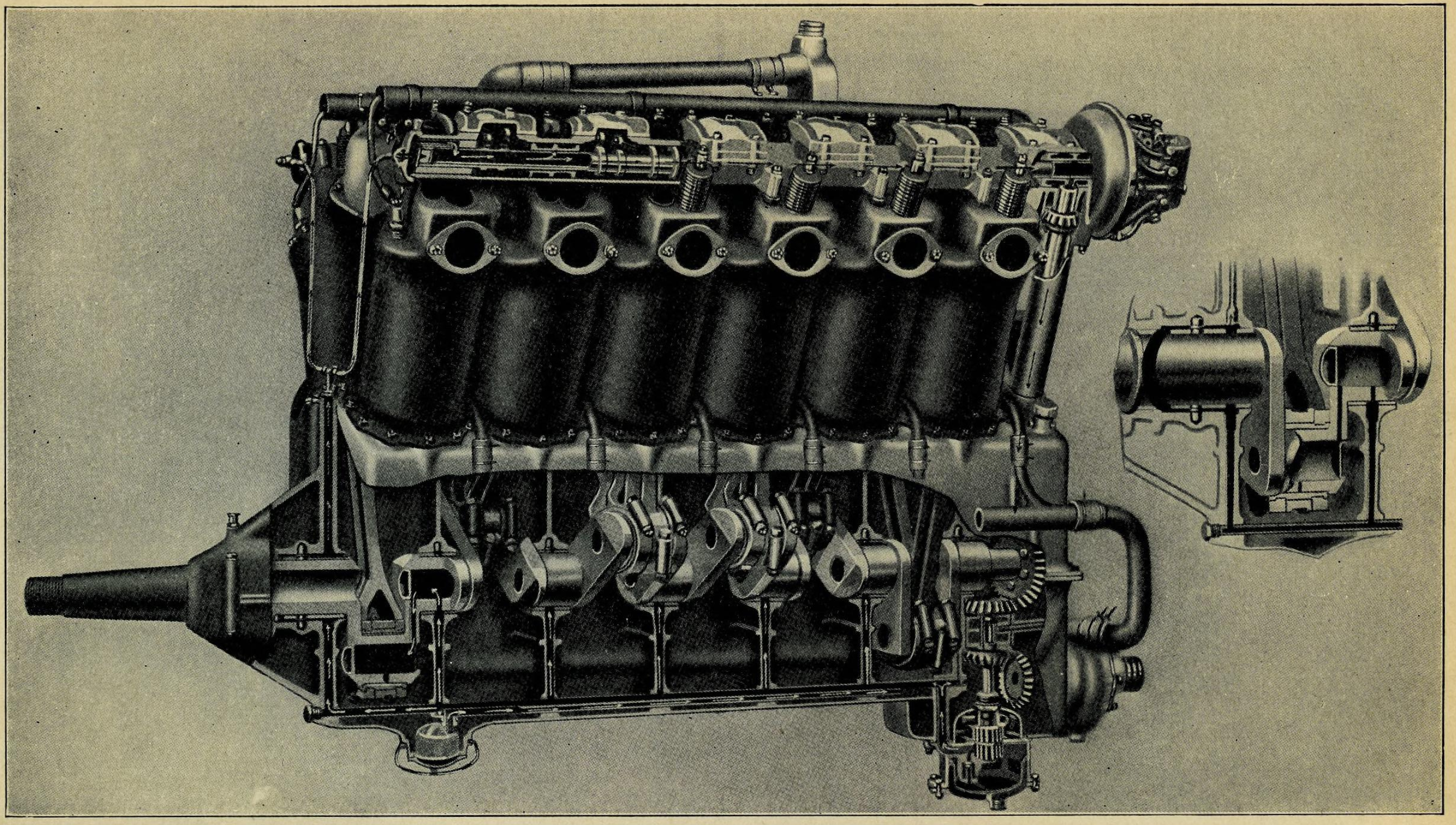
The MkVIII’s V12 engine (US Army Preliminary Handbook for the MkVIII)
The 37 ton tank was to be powered by an American V12 aircraft petrol engine manufactured by the Liberty company. Although a cheaper, water-cooled Liberty was eventually used in the American tanks. The British developed a similar 12 cylinder engine from Ricardo. This, in theory, produced 300 horsepower with a top speed of just over 6mph and a range of just under 40 miles. The MkVIII’s engine was moved from the centre of the tank to a separate engine compartment at the rear of the tank. This not only reduced engine heat and fumes in the fighting compartment but also made communication easier. Some sources also suggest that the MkVIII was the first tank to have an electronic intercom system.
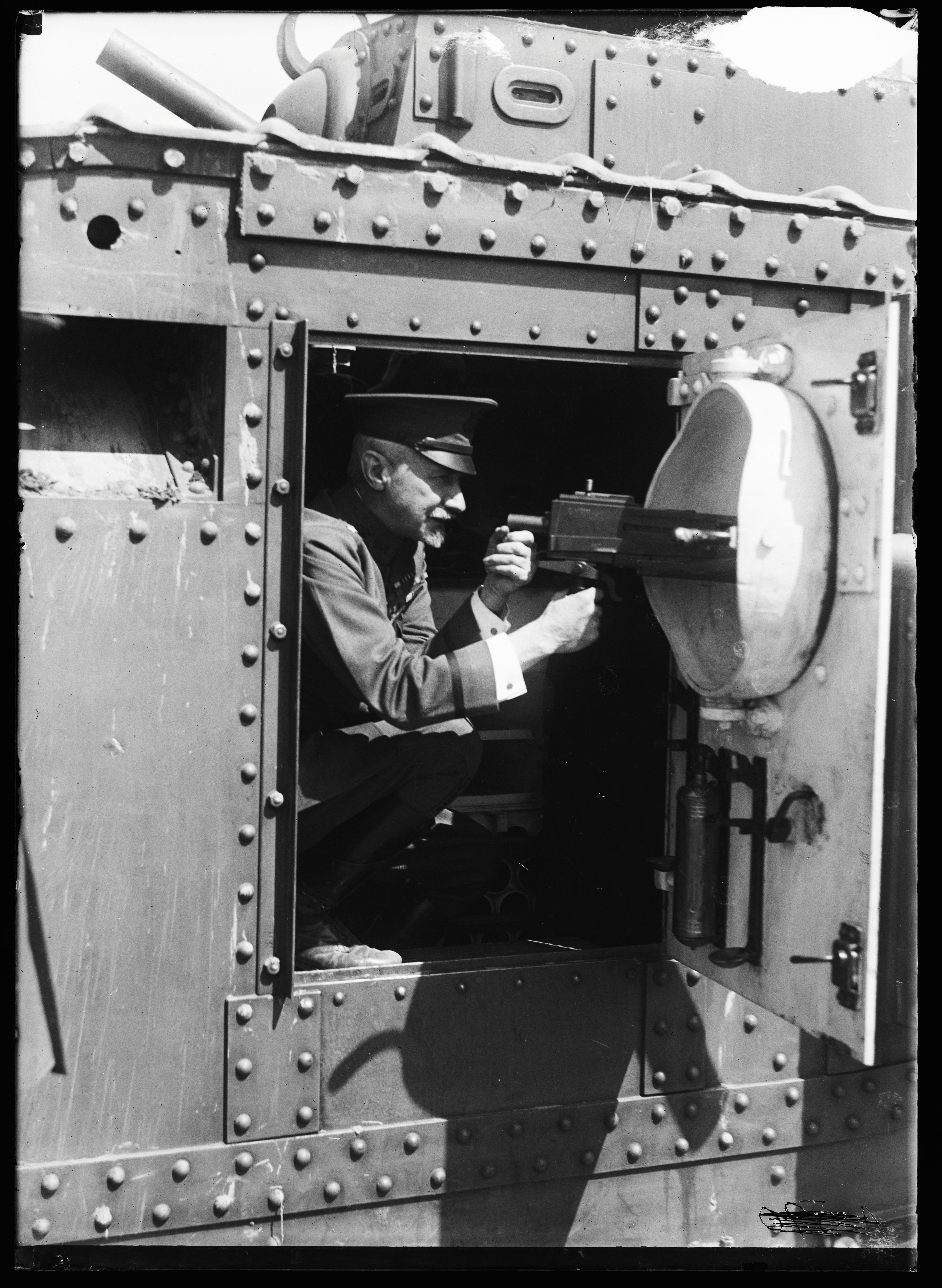
An officer illustrates how one of the tank’s ball mounted machine guns worked – the gun itself is an M1919 tank machine gun (US Library of Congress)
The American Preliminary Handbook for the MkVIII listed the tanks as being equipped with 7 ‘Hotchkiss .303-inch machine guns’, these are likely to be Hotchkiss Portative MkI*s popular in British service. In US service, however, the tanks were likely later equipped with the new Browning M1919 Tank Machine Guns. The tank carried 182 rounds of 6pdr ammunition and an additional 26 smoke rounds as well as 21,000 rounds of machine gun ammunition to keep the 7 machine guns fed.The tank’s armour was also increased lightly from the previous MkV, with 16mm of frontal armour and between 10 and 12mm at the sides. Less vulnerable areas had armour 6mm thick.
A partial cutaway view of the tank (US Army Preliminary Handbook for the MkVIII)
The American MkVIIIs were initially planned to be manned by an eleven-man crew made up of a driver, commander, two gunners and two loaders to man 6pdrs, four machine gunners and a mechanic. Later crew complements probably dispensed with two of the machine gunners as the US MkVIIIs operated during the inter-war period dispensed with two of the midships machine guns. The British crew was planned to be smaller with 8-men fighting the tank, made up of a driver, commander a pair of gunners and loaders for the main guns and two machine gunners who were tasked with manning the tank’s various machine guns. Impressively the 34 feet long tank also had room for as many as 22 infantry to be transported.
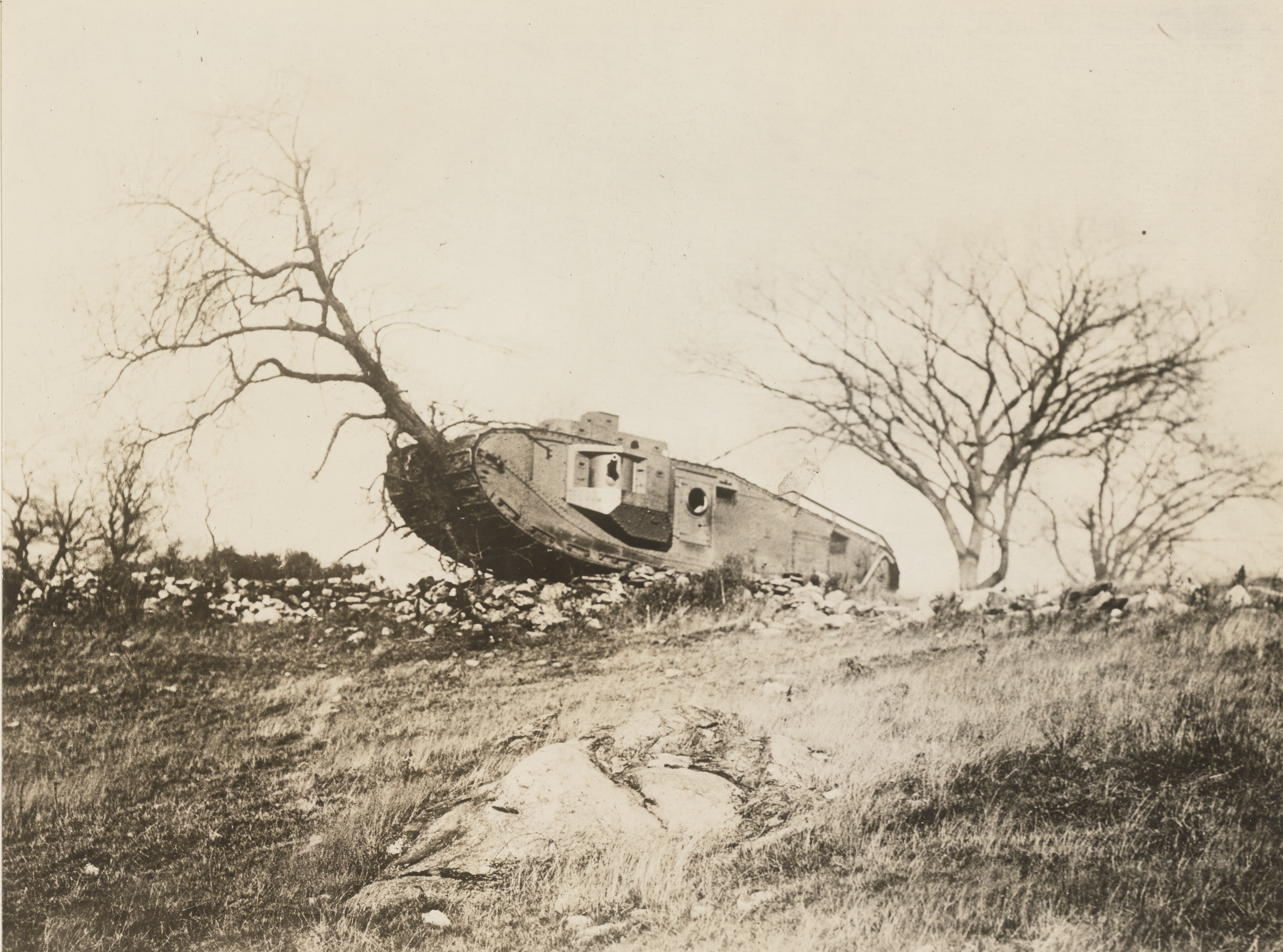
A MkVIII demonstrating its power by destroying a tree during testing (US National Archives)
As an allied collaborative project the production of parts was to be a collaborative effort. Britain was to contribute armour plate, structural frame work and armament. The American contribution was to include the automotive parts including the engine, brakes, drive sprockets, gears and transmission.
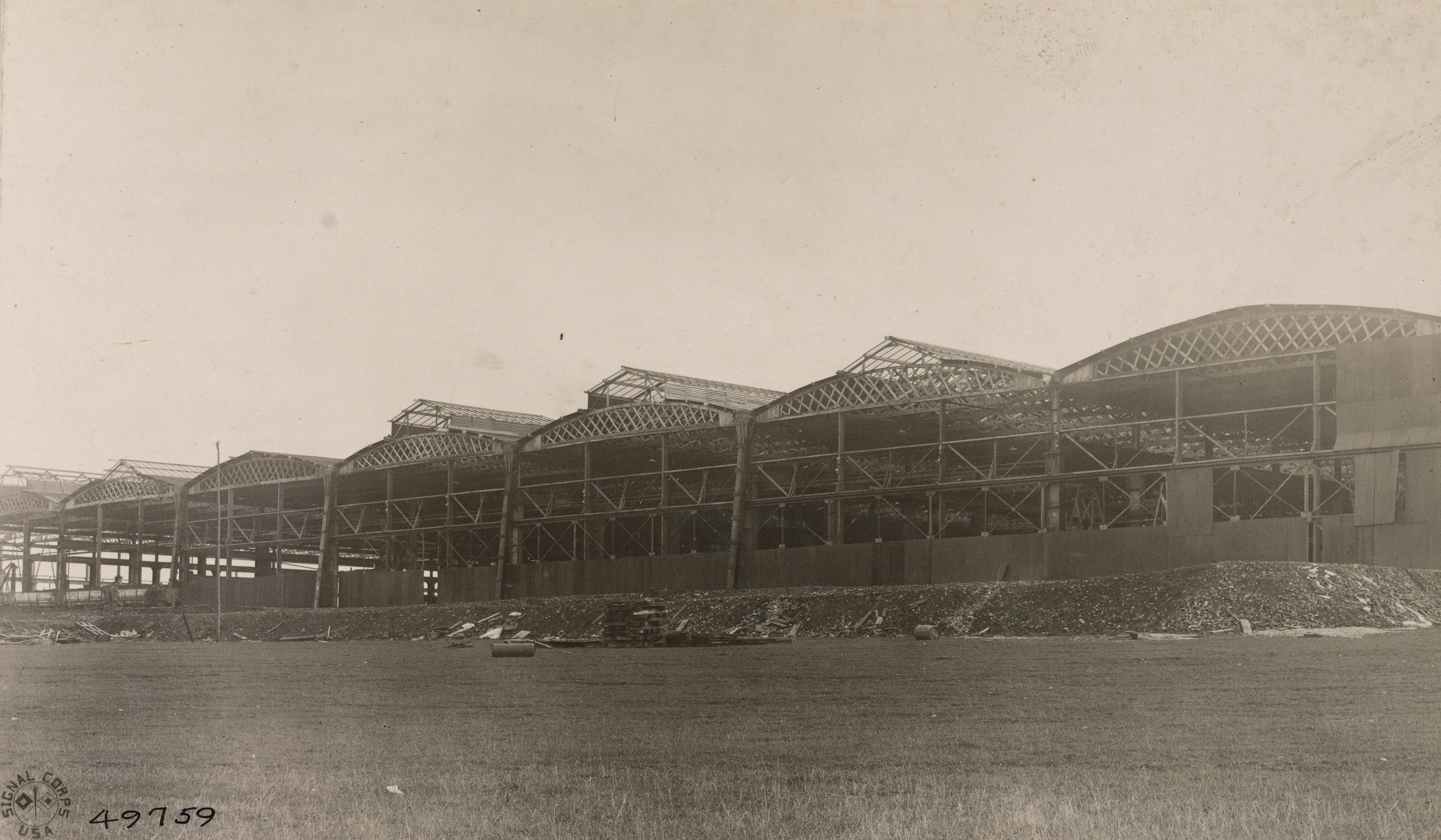
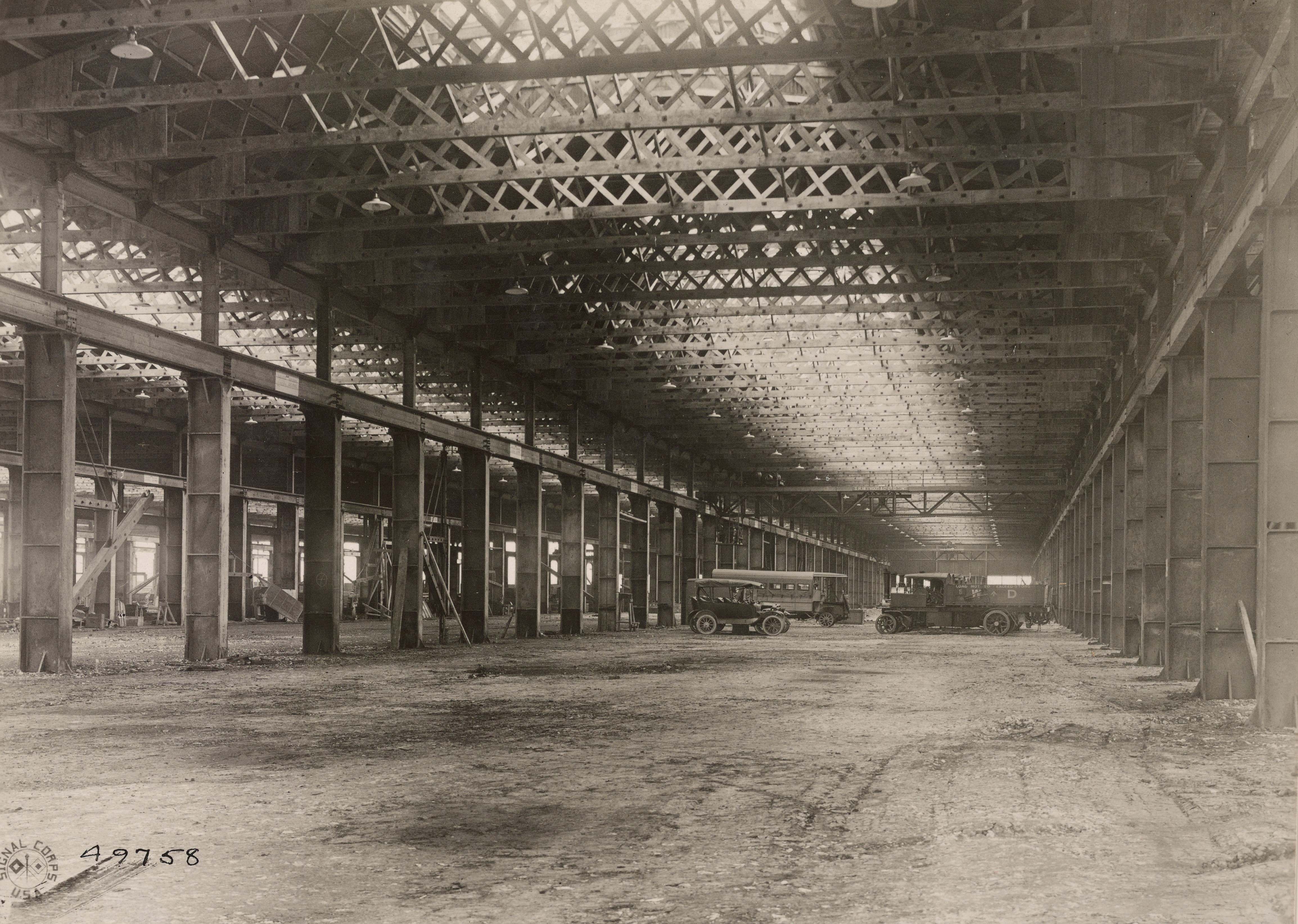
The French were largely uninterested in British heavy tanks and their primary contribution to the MkVIII project was a factory site near the village of Neuvy-Pailloux, 165 miles south of Paris, in central France. Critically located well away from the fighting on a main rail route north, through Issoudun. Construction of the impressive factory appears to have begun in early 1918, with the framework of seven long production halls and the installation of a powerplant and generators and the building of railway sidings completed before the armistice in November 1918. Production barely got underway in Britain, let alone in France. Contemporary photographs taken in January 1919, by the US Army Signal Corps show the factory with its roof in various stages of completion, its shop floors unfinished and empty and open to the elements. The factory would eventually be completed and used by the French army as an artillery park and later a maintenance depot.
The incomplete Neuvy-Pailloux factory c.1919 (US National Archives)
The oringal plan was for the tank parts to be shipped across the channel and the atlantic through France’s western coastal ports to be shipped by rail to Neuvy-Pailloux where they would be assembled into working tanks. It was envisaged that the workforce would be made up of Chinese labourers with British and American foremen and managers.
Inside the incomplete factory (US National Archives)
As many as 3,000 tanks were planned for 1919. The British intended to build 1,450 MkVIIIs of their own use in addition to the 1,550 to be produced for general allied use. The British tank parts were to be manufactured in Manchester, by the various workshops of the Manchester Tanks Association, and in Glasgow, by the North British Locomotive Company. Mass production in Manchester never got underway and the initial British MkVIIIs were built in Glasgow – just 24 are believed to have been built, all but six of these were scrapped almost immediately. The first American tanks were assembled by the Locomobile Company of Bridgeport, Connecticut. The American-assembled MkVIII completed acceptance trials in the spring of 1919. With the end of the war the US order was reduced from 1,500 to 100. 100 sets of hull components were bought from Britain and assembled with corresponding American parts at the Rock Island Arsenal.
A US MkVIII at Camp Meade, c.1921 (US National Archives)
The MkVIII was the last of the British rhomboid heavy tanks. The handful of British MkVIIIs built never entered service but the 100 American tanks along with American built M1917s, MkV Heavies and Renault FTs brought back from France, formed the backbone of the US Tank Corps throughout the early inter-war period. The US MkVIIIs remained in use as training tanks until 1932. Today, just three are believed to survive; two in the US and one in Britain.
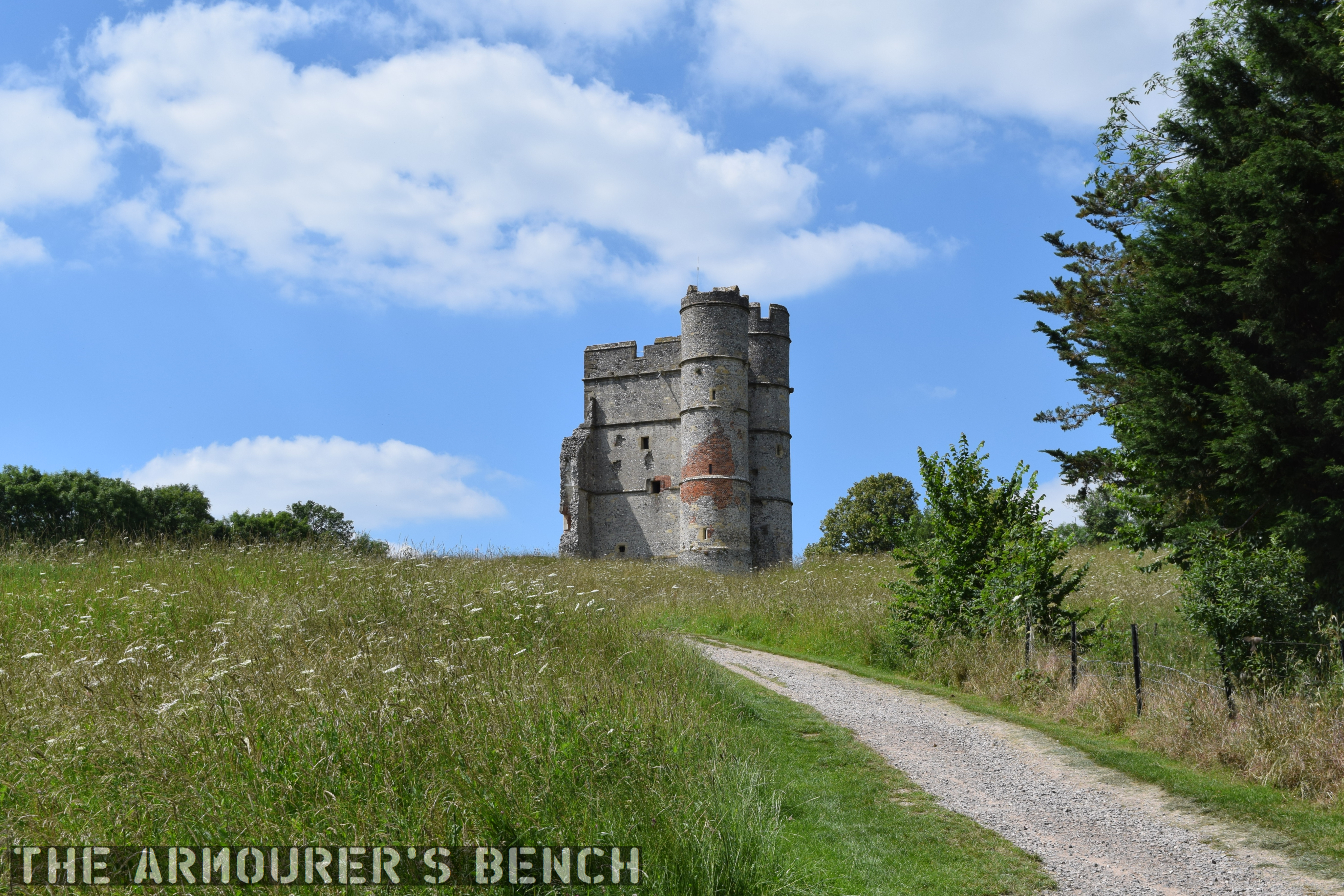
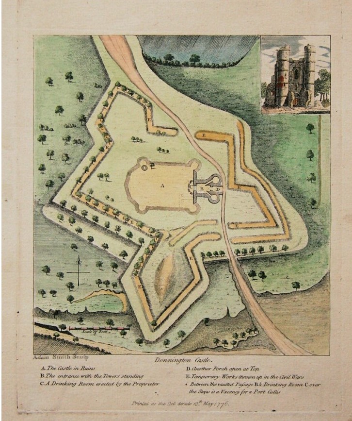
With many of us being stuck in COVID-19 imposed lockdowns I thought now would be a good time for a video-walk around Donnington Castle. Think of it as a virtual stroll. The 14th century castle found itself embroiled in a long siege during the English Civil War (1642–1651) with extensive earthworks built to defend the old castle.
The approach to Donnington Castle (Matthew Moss)
Donnington Castle in Berkshire is sited at the top of a hill overlooking the River Lambourne, a mile north of Newbury. It was built by its original owner, Richard Abberbury the Elder, under a license granted by King Richard II in 1386. The castle was designed as a fortified residence with a rectangular enclosure with a three-storey round tower at each corner and two square towers midway along the longest sides. The gatehouse, the only remaining part of the castle is a three-storey rectangular building with two, four-storey, round towers flanking the entrance. The wall opposite the gatehouse bows outwards.
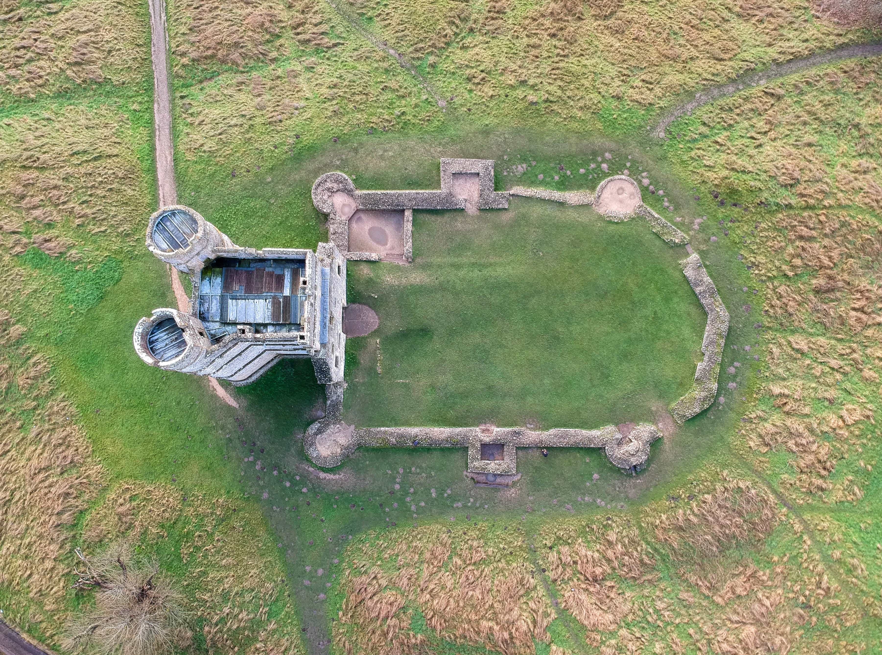
Aerial view showing the outline of the castle’s walls (Matthew Prior)
The castles walls probably enclosed a hall, kitchens, storerooms and accommodation for guests with the main quarters being in the gatehouse keep. While not an elaborate, larger or militarily complex as some other castles it still imposing sight.
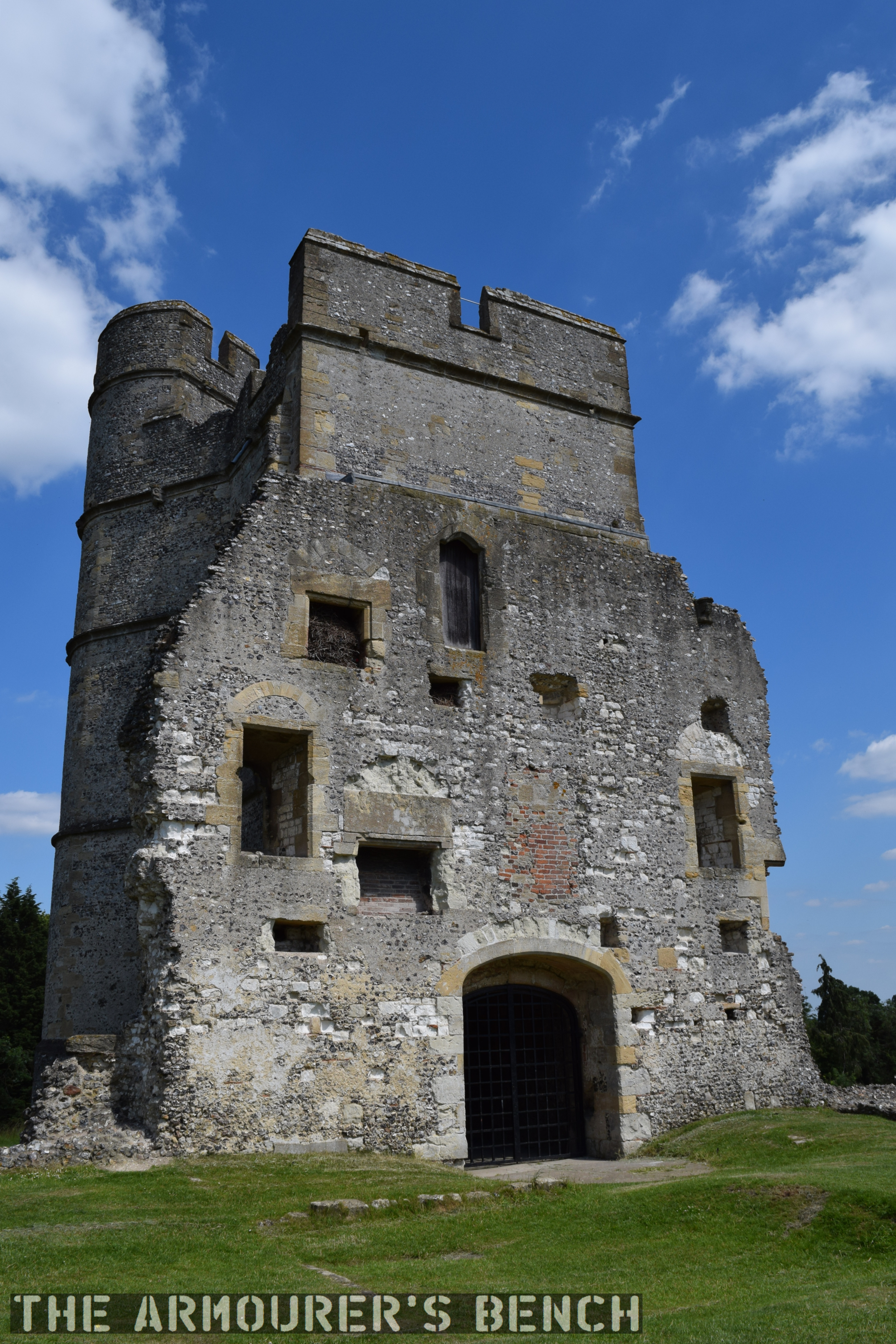
The rear of the gatehouse shows the outline of former rooms which were damaged and demolished. Note the later brick used to repair some damage (Matthew Moss)
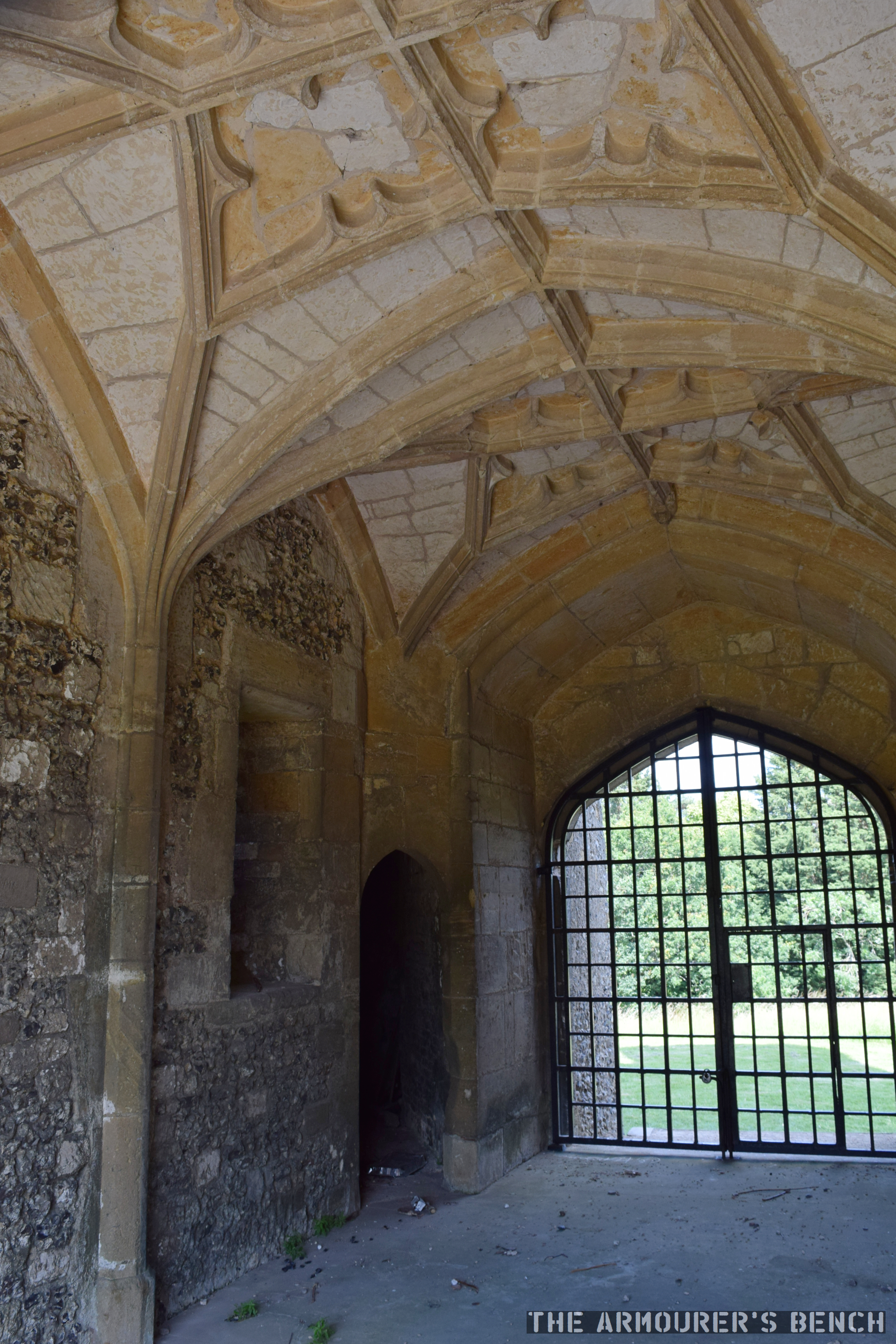
The vaulted and corniced ceiling inside the gatehouse entrance, hinting at the castle’s role as a home more than a military position (Matthew Moss)
Both Henry VIII and Queen Elizabeth I visited the castle during the Tudor period. The castle didn’t see action until the 1640s and the outbreak of the English Civil Wars (1642-1651). While the castle has been owned by a Parliamentarian family, the Royalists took control of the caste in 1643 and began fortifying it. Sir John Boys set about building elaborate star-fort defences around the original medieval castle. Boys built a set of angular trace Italienne at the considerable cost of around £1,000. Donnington Castle was one of many medieval castles that saw new life during the Civil Wars. Old castles along with churches and country houses were re-purposed and hastily defended by new earthworks.
18th Century map showing outline of the castle’s Civil War defences
The castle’s new defences included four new bastions, with emplacements for cannon, ditches and a palisade wall. Royalist forces at the fort initially numbered just over 200 men and four cannon. The Second Battle of Newbury was fought within sight of the castle in October 1644 and after the battle the castle’s defences were reinforced by a number of large guns left behind by King Charles’ retreating forces.
The castle itself was attacked numerous times during the war, during the second attack on the castle part of the wall was damaged. The castle had to be and had to be relieved by Royalist forces twice the final siege in March 1646 began. The castle was badly damaged after the siege with its walls and outer towers hardest hit but remained defensible. With no hope of relief the garrison surrendered and were allowed to march out with their colours.
As with so many other castles after the war Parliament voted to demolish it and only the gatehouse was left standing. It is now a scheduled monument.
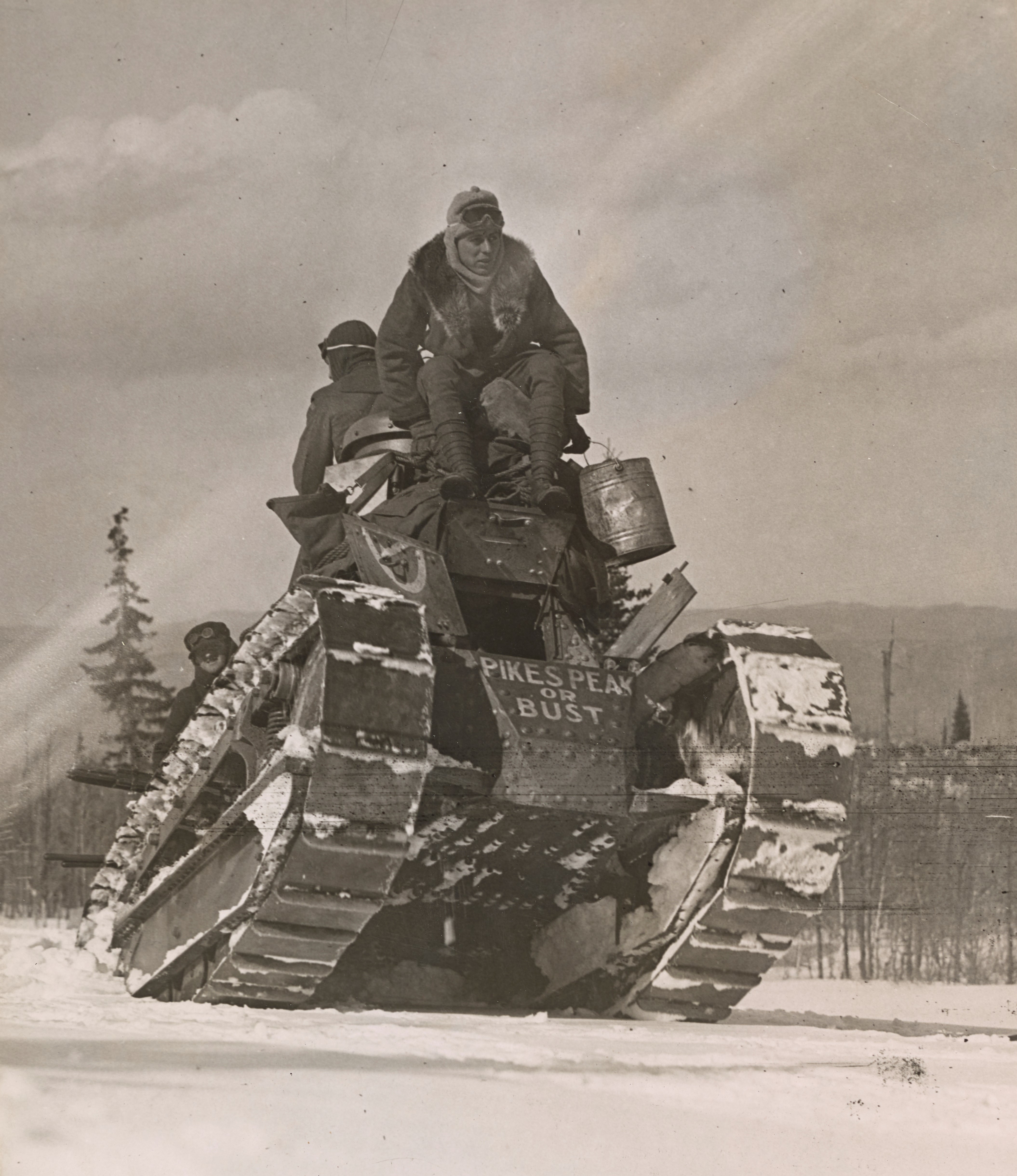
In April 1919, a lone US-built M1917 light tank climbed over 11,000 feet up a mountain in Colorado. We are lucky enough to have some original photos and footage of the tank’s climb up Pikes Peak in the Rocky Mountains.
The tank with ‘Pikes Peak or Bust’ painted on its hull (US National Archive)
Why was a tank driving up a mountain?
Simply put the expedition was a publicity stunt to help raise cash to pay off America’s war debt. By 1919 the cost of US involvement in World War One had reached $32 billion – that’s around $547 billion today.
The purpose of the stunt was to encourage Americans to purchase ‘Victory Liberty’ War Bonds which would help pay off some of the debt accrued by the war. This was the fifth, and final, round of Liberty Bond sales. The drive began in mid-April 1919, and aimed to sell $4.5 billion of government bonds.
The tank arrived in Colorado Springs at the beginning of April and on the 14th a crowd of nearly 1,000 people watched Mrs W.H.R. Stote, the chairwoman of Colorado Springs’ Victory Liberty loan committee, christened the tank ‘Little Zeb’ – after explorer Brigadier Zebulon Pike – who led an expedition that attempted to climb the mountain in 1806)
Mrs Stote reportedly declared “I charge you with making the trip to the summit. As the Victory Loan shall not fail, you must make it to the top!” The tank’s commander Sgt. A.H. Worrell, told The Colorado Springs Gazette that he had “driven tanks over trees and trenches on the western front and I am betting we get to the top.”
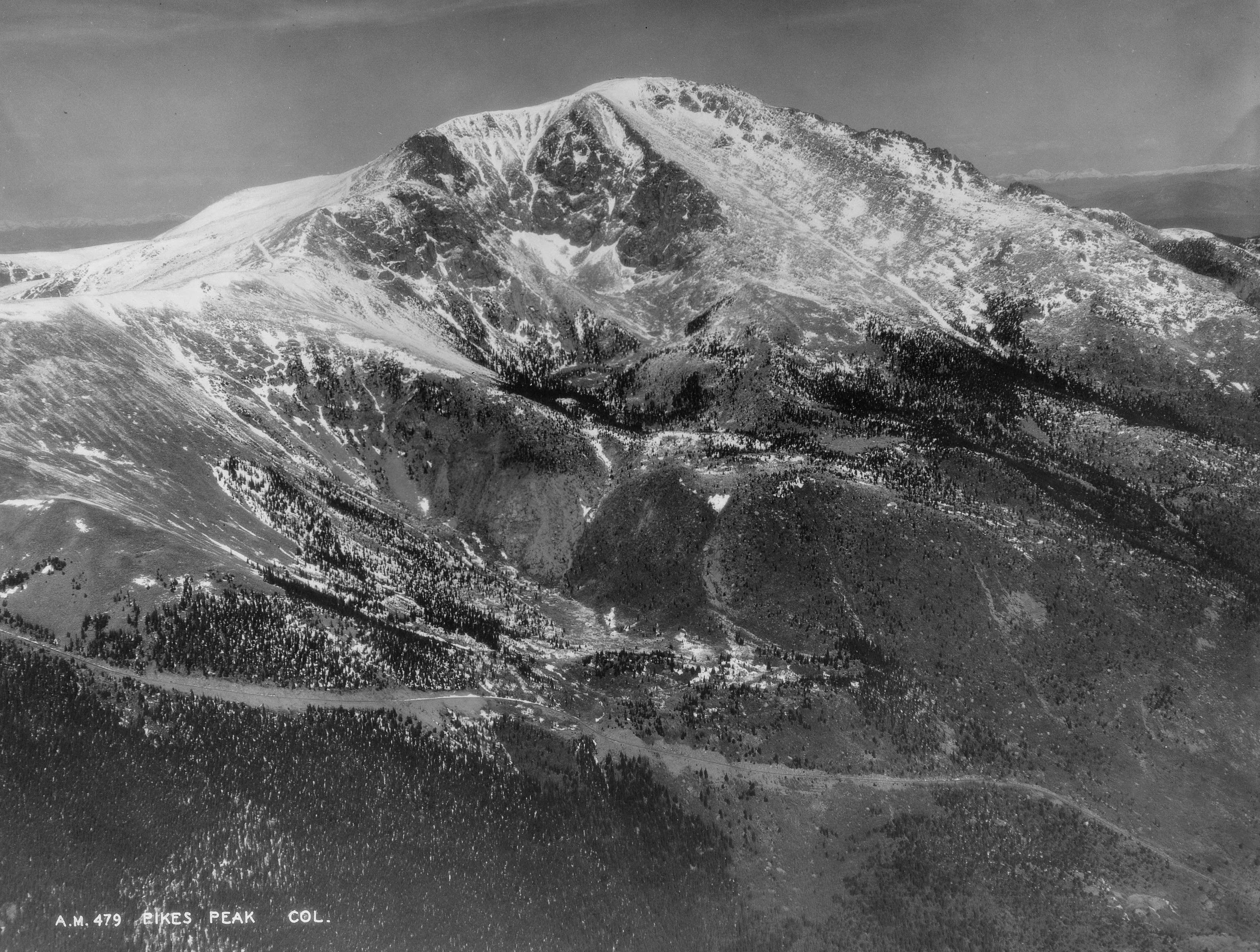
The road up to the summit of Pikes Peak, photographed in 1934 (US National Archive)
At the time the 19 mile road up to Pikes Peak was said to be the ‘World’s Highest Motor Drive’ with the summit at 14,115 feet (or 4,302m). Cpl. Howard Brewer, the tank’s driver told reporters “I know we can climb it. Given time, the tank could go to the top of the world.” In terms of publicity having the tank make it up the mountain would certainly have been quite a feat.
On the front of the tank’s hull the words ‘Pike’s Peak or bust’ were painted in white – this is a reference to a phrase coined by prospector’s during the Pike’s Peak Gold Rush of the 1860s.
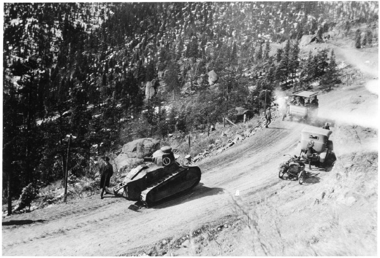
The tank on the road up Pikes Peak (Pikes Peak District Library)
The tank was driven by Corporal Howard Brewer and tended by a crew of mechanics and support vehicles. The road which climbed the mountain was unsurfaced and had only been completed in 1916. The tank’s ascent began on April 15, and incredibly over the next two days the tank climbed to 11,440 feet, 13 miles along the road and through several deep snow drifts, reportedly up to 20-feet tall, before a track plate snapped. After repairs the tank and support convoy pressed on – but the tank never made it to the summit. Not because of mechanical failure but unbelievably because it was needed to appear in other Colorado towns as part of the Victory Loan drive.
While the tank may not have reached the very top of the mountain, it unsurprisingly became a record breaker – setting the first elevation record for tanks. Western Union claimed that it also set a distance record for continuous distance travelled and penetrated the farthest into the snow than any other vehicle had ever done at that time of year – battling snow drifts up to 20 feet tall. While the US-built M1917 was never tested in battle the drive up the mountain proved it was a capable, hardy vehicle – demonstrating the tank’s abilities.
Bibliography:
Various photos and contemporary footage taken from the US National Archives (source)
Additional photos held by the The Manitou Springs Historical Society (source)
‘Army’s Tank Assault on Pikes Peak Was About More Than Being Macho’, The Gazette, M.L. Cavanaugh, (source)
U.S. Economy in World War I, Economic History Association, (source)
This week TAB hit 4,000 subscribers! Thanks for all your support over the last couple of years. I filmed this update on Tuesday during a recent research trip in the south of England. I visited Fort Nelson near Portsmouth and thought I’d film a quick update while I stopped for a break.