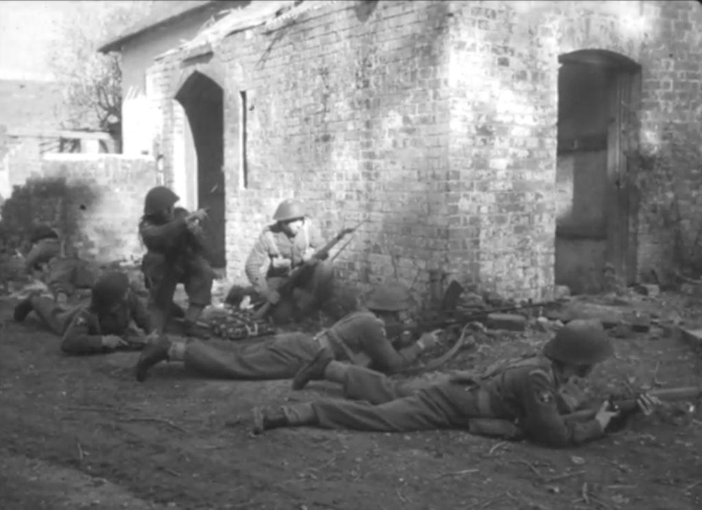
Recently, while looking though British Army Cold War training films, I stumbled upon something I never expected to see: a clip of an MCEM-2 firing! I was searching through British Cold War training films and watching a 1953 film titled ‘Village Clearing’ at first it seemed pretty standard fair albeit showing an impressive set-piece of tanks attacking a village. And then about 8 minutes in I spotted something unusual, the prototype MCEM-2, in the hands of one of the village’s defenders.
The 1953 training film shows a company size attack by the Royal Welch Fusiliers on an enemy strongpoint but then shows a section/squad assault on a building. The opposing force or OPFORCE are wearing airborne HSAT helmets and are armed with American weapons including M1 Garands, some first pattern M1918 BARs and a lone MCEM-2! This was likely done to differentiate the British troops from the OPFORCE – either they wanted a generic look or didn’t have any soviet weapons or kit available as is seen in later training films. My guess would be that the prototype may have come from the British Army’s Small Arms School Corps Collection which has historically maintained a working collection of foreign, historic and prototype weapons for familiarisation and training purposes.
The MCEM-2 or Machine Carbine, Experimental Model No.2 was developed by a Polish engineer, Jerzy Podsedkowski. Work on the design began in 1944 but it was not seriously tested until after the end of the war. We can see from this brief clip that Podsedkowski’s design was small, compact and innovative. It fed from an 18 round magazine which like the later Uzi, Sa.23 and RAK Pm.63 was inserted into the pistol grip. While this kept the weapon compact and theoretically holster-able the MCEM-2’s high rate of fire, around 1,000 rounds per minute, meant that it was expended extremely rapidly.
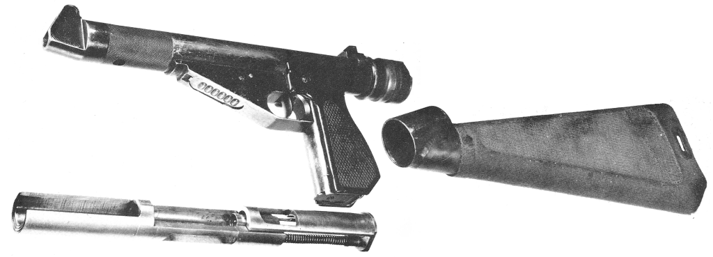
The MCEM-2 disassembled (via Firearms.96.lt)
The MCEM-2 (Machine Carbine Experimental Model No.2) was a small, compact, innovative design. The weapon had a holster stock and a wrap-around breech block which was inclosed in a tube metal receiver. We can see the bolt in this photograph. In 1946 Podsedkowski, assisted by another Polish engineer, Aleksander Ichnatowicz, improved the MCEM-2, seeking to slow its rate of fire with a heavier bolt. The MCEM-2 was tested at the Royal Navy’s Gunnery School at HMS Excellent in August 1946. Excellent’s Commandant Michael Le Fanu, later an admiral and First Sea Lord, noted in his report that it was a “well engineered weapon, handy to carry about and suitable for use by seamen” but did note that “the high rate of fire makes the weapon uncontrollable in automatic and dangerous in the hand of semi-skilled users.”
Despite improvements the new MCEM-6 was eventually rejected with a Harold Turpin design favoured before it too was rejected. Hopefully, we’ll be able to take a look at some of these designs upclose in future articles/videos.
If you enjoyed this video and article please consider supporting our work here. We have some great perks available for Patreon Supporters – including custom stickers and early access to videos! Thank you for your support!
Today, we’re going to take a look at a little known type of weapon which rose to prominence in around the time of the First World War with a number of examples being developed and some even tested. As you can see from this footage it’s something pretty unconventional, seen here mounted on the back of a truck – is a centrifugal machine gun.
I found this short footage while doing some digging through the online catalogue of the US National Archives. The centrifugal machine gun was not a new concept by the time this footage was filmed in the early 1920s, sadly the footage notes done give an exact date.
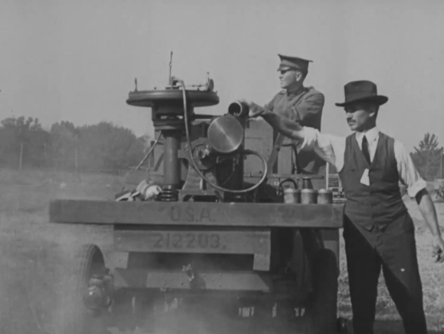
A still from footage of the demonstration (US National Archives)
While the technology had risen to a new prominence what was the allure of centrifugal machine guns? The principle of centrifugal force – an inertial force which appears to act on objects moving in a circular path, directs them away from the axis of rotation. As a result a centrifugal machine gun required no propellant powder to propel the projectile, or a case to contain it, nor a conventional rifled barrel to stabilise the projectile. Once released from the axis of rotation the projectile travels on a linear trajectory until it expends its energy. It works along the same principle as a primitive sling. The primary issue is providing power to exert the centrifugal force and a means of accurately firing the projectiles.
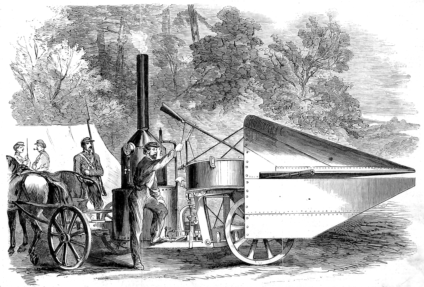
Some of the earliest work on centrifugal guns was done in the late 1850s in the US. The hand-crank or steam powered guns patented by William Joslin (US #24,031), C.B. Thayer patent for a ‘machine gun’ in August 1858 (US #21,109) and Charles S. Dickinson (US# 24,997) in 1859. Dickinson went on to secure financial backing from a wealthy Maryland industrialist Ross Winans and developed a steam powered version of his gun. Despite gaining much press attention Dickinson’s centrifugal gun saw no action during the US Civil War. In 1862 G.C. Eaton and S.W. Turner also patented a ‘machine gun’ (US #37,159).
An illustration of the Winans Steam Gun, Frank Leslie’s Illustrated Newspaper, May 1861
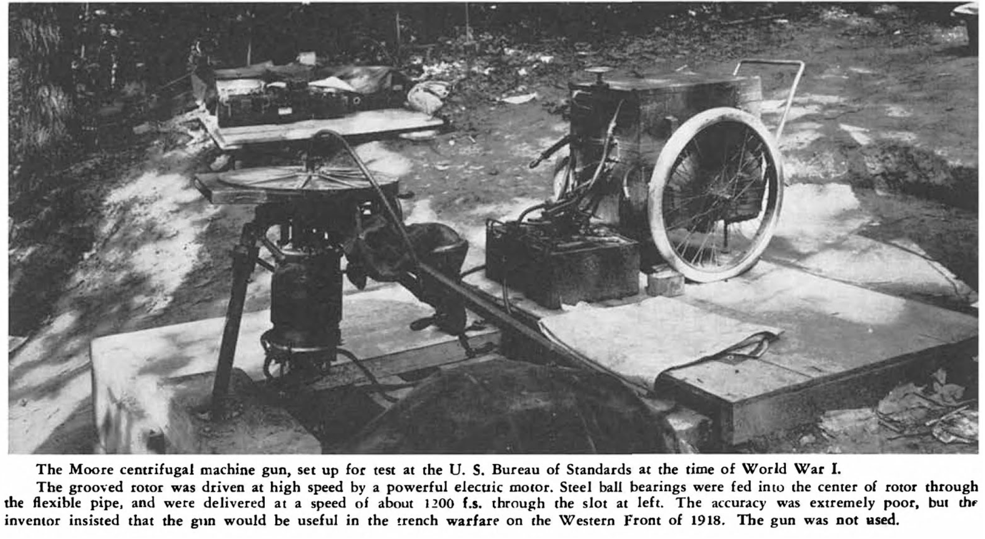
It wasn’t until World War One that the concept began to be considered again. In June 1918, Major Edward T. Moore and Saul Singer filed a patent for a centrifugal machine gun powered by an electrical motor (US #1,332,992). The motor spooled up the centrifugal barrel assembly to rotate extremely quickly and impart centrifugal force on projectiles. According to Julian Hatcher the gun could fire steel ball bearing projectiles at approximately 1,200 feet per second. Fire was controlled by a stop pin in the ammunition feed tube. Moore claimed the weapon could fire a projectile 1.5 miles with enough force to kill a man. He also suggested the weapon’s rate of fire approached 2,000 rounds per minute. It appears that Moore’s gun may have been tested in 1918 but Hatcher described its accuracy as ‘extremely poor’.
Photograph of Moore’s gun during testing (Hatcher)
Another centrifugal design developed during World War One was E.L. Rice’s half-inch centrifugal gun, sadly I’ve been unable to find any photographs or drawings of Rice’s design but the weapon was submitted to the US National Research Council in 1917. The NRC’s 1919 report states that the gun had been further developed by the NRC’s Physics Division in Pittsburgh but work had been slowed by “a common defect which has been difficult to eliminate”. Despite what the report described as ‘considerable headway’ the weapon was subsequently abandoned amid some controversy about credit for the design.
There seems to have been something of a centrifugal machine gun craze with several more patents filed between 1917 and 1926. A Scientific American article from March 1918, even noted that “every so often the daily press becomes enthused over a new centrifugal gun.”
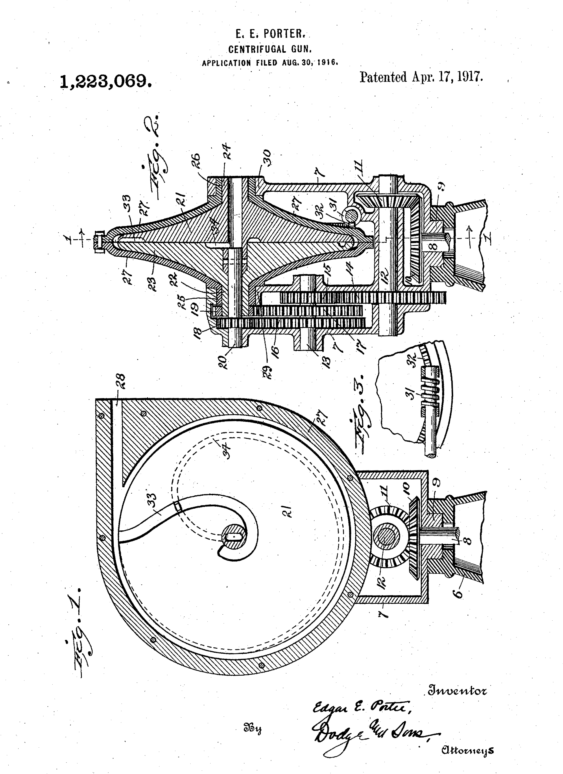
One of the earliest patents granted appear to have been for a design by E.E. Porter, granted in January 1917. This was followed in July 1919 by inventor, Herbert A. Bullard being granted a patent (US #1,311,492) on a design which fired a disc rather than a ball. At the same time T.A. Gannoe was granted a patent (US #1,309,129) for a large, complex looking gun shown mounted on a pedestal.
In 1920, F.R. Barnes (US #1,327,518) and W.W. Case (US #1,357,028) were also granted patents which had been filed in 1917. In late 1921, Levi Lombard was granted a patent he had filed in March 1918, his gun even appeared in Scientific American. It appears to be notably smaller than Moore’s gun and has a spade grip for aiming. This was followed in 1923, by an interesting patent from Joseph T. McNaier for a centrifugal gun that could be powered by an electric or petrol engine, some of the patent diagrams show how the gun might be placed in an armoured car or aeroplane (US #1,472,080). Intriguingly, McNaier and Moore appear to have known each other quite well and were partners in a law firm together.
Here’s a gallery of some of the various patents mentioned above, not all are as detailed or as advanced as others:
The question is which of these guns is featured in the footage. The most likely bets are the Moore or the Czegka. Sadly, with only a side view and just 18 seconds of footage we don’t have much to go on. The accompanying reel notes, describing what is seen in each section of the film, describes the gun as being in the “experimental stages only” and that the prototype seen here “is intended for use as aircraft armament, for tanks and for landing parties of the Front line trenches.”
Sadly, we don’t get to see how the gun works but we can see the operator feeding the ball bearing projectiles into the hopper which has a powered feed system – he empties two cylindrical containers of balls into it one after another. It is unclear how many rounds might be in the containers, perhaps 50 each. The gun and its motor are mounted on a truck bed with a soldier in uniform, possibly aiming the weapon via a tiller.
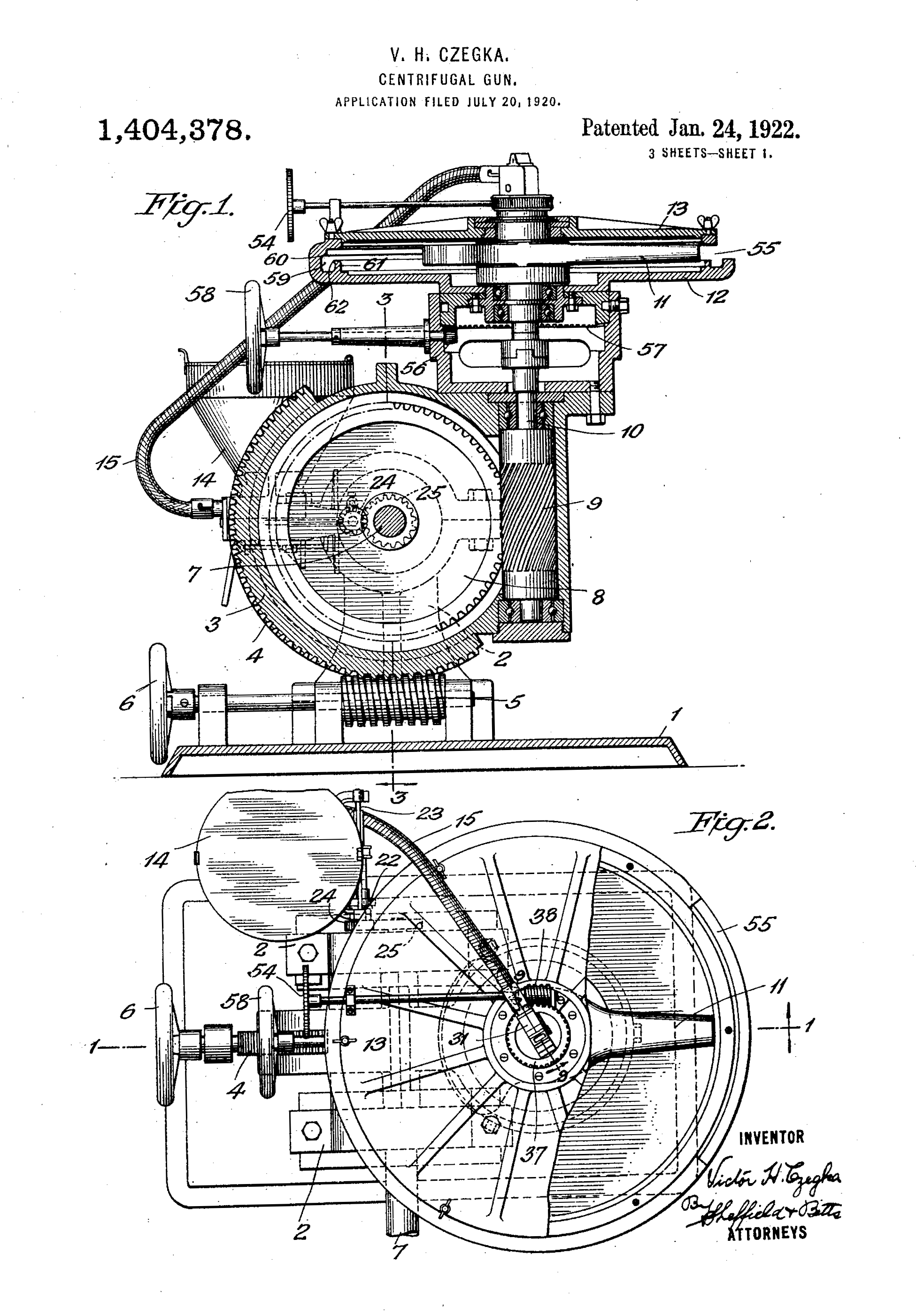
Another of the later designs dating from the period came from Victor Czegka, a US Marine Corps Technical Sergeant, who is perhaps best known as the supply officer of Admiral Richard Byrd’s first two expeditions to the Antarctic. Czegka was granted a patent for a centrifugal machine gun in January 1922 (US #1,404,378).
Czegka’s 1922 patent (US Patent Office)
With some further digging I managed to find several articles referring to the gun in the US Army Ordnance Journal. Interestingly, a photo from the same demonstration is printed in one article, from late October 1920, with the caption confirming the man loading the weapon is the inventor, however, he isn’t named. The footage was filmed during the Second Annual Meeting of the US Army Ordnance Association. Another article dating from May 1921, also notes that the tests took place at Aberdeen Proving Ground, with the gun firing at 16,000 revolutions per minute which required 98 horsepower from the engine powering it. The gun apparently needed a “very rapid increase in power required for operation” when the speed of its revolutions was increased incrementally from 12,000 to 16,000 rpm. The article concluded that “a horsepower above 100 would have no material effect in increasing the speed” suggesting that a much more powerful, and therefore larger, engine would be needed to increase the revolution rate.
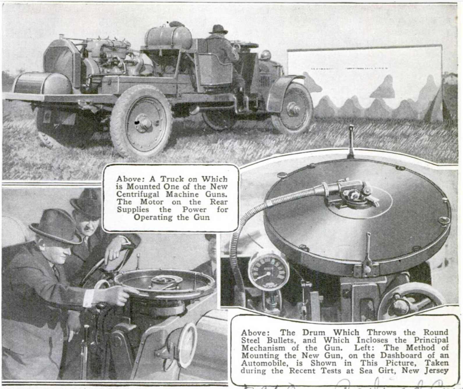
While researching I came across this set of images from a March 1922 edition of Popular Mechanics showing an unnamed centrifugal gun set up on a truck, powered by an engine on the truck bed. From the images it appears to be a gun similar to Moore’s with a single rotating ‘barrel’. The captions also note that the photographs were taken in New Jersey and Moore was a Major with the New Jersey National Guard, which may also indicate the gun is Moore’s.
Despite various designs seeing some US military testing none were ever adopted and relatively little information on them is available. It seems that they were relatively cumbersome weapons with extremely varying accuracy but this footage at least proves the concept. A short report in a may 1921 edition of Scientific American may shed some light, stating an unnamed gun was rejected “because of its great weight and its inability to obtain high initial velocity” concluding that “no centrifugal gun can have military value”. It appears that the range of the centrifugal guns was limited to the speed of their revolution, which in turn was limited by the power of the engine and motor that powered them. The larger the motor, the more cumbersome the weapon system was.
There are very few photos of centrifugal machine guns so stumbling across actual footage of one guns actually operating is very exciting. They are a fascinating tangent to the history of the machine gun – one that occasionally still garners interest.
Update
A viewer shared a Pathe Newsreel with us which included more footage from the same demonstration. The footage title suggests it dates from 1938, however, I believe this to be incorrect.
Despite the incorrect date the footage shows us the internals of the centrifugal gun and its aiming mechanism!
Here are few screen captures from the footage:
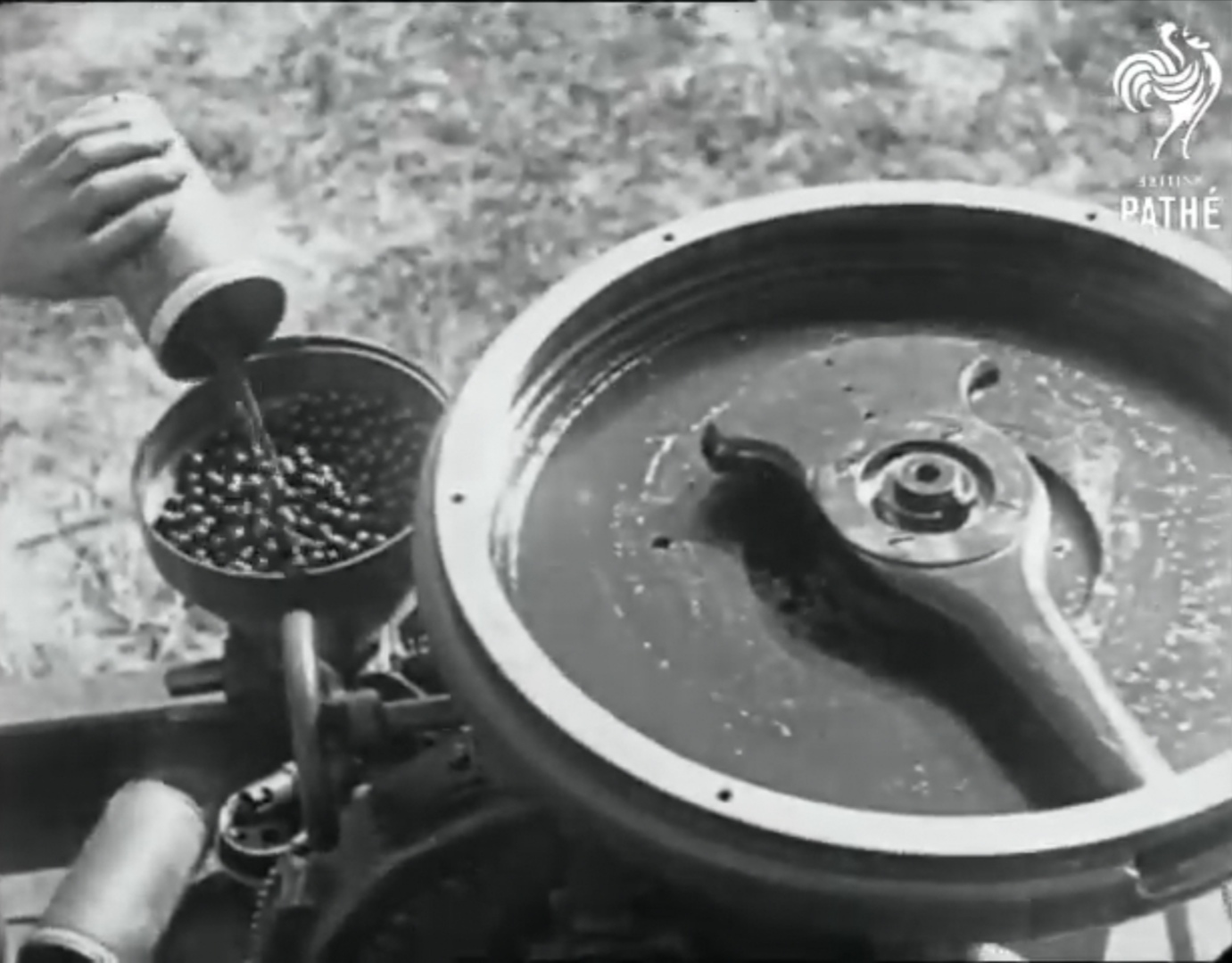
The gun’s hopper being loaded (Pathe)
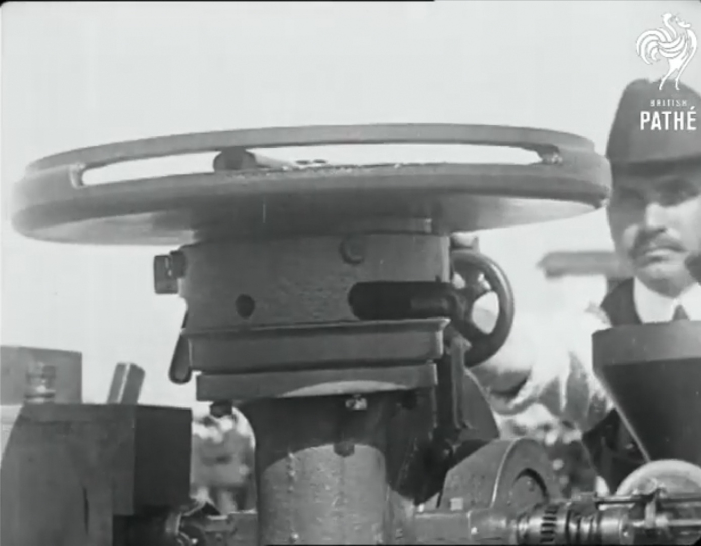
A front view of the weapon, showing the slit from which projectiles fired through, and a better look at the operator’s face (Pathe)
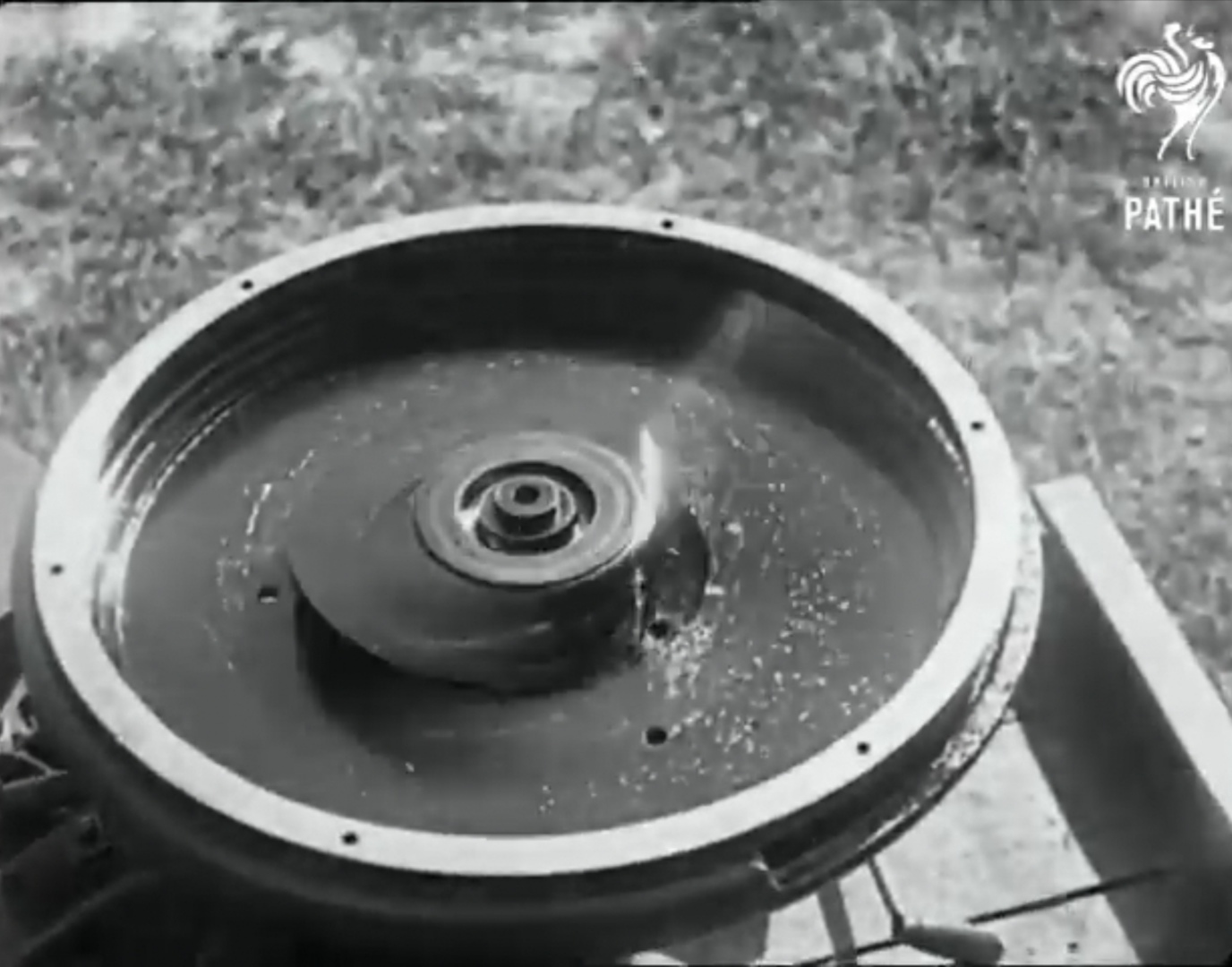
The gun with its top cover and feed system removed showing the centrifugal barrel spinning up – a info card from the footage suggests it is spinning at 12,000 rpm (Pathe)