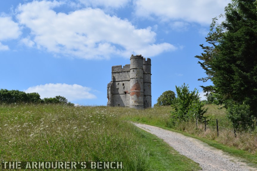
With many of us being stuck in COVID-19 imposed lockdowns I thought now would be a good time for a video-walk around Donnington Castle. Think of it as a virtual stroll. The 14th century castle found itself embroiled in a long siege during the English Civil War (1642–1651) with extensive earthworks built to defend the old castle.
The approach to Donnington Castle (Matthew Moss)
Donnington Castle in Berkshire is sited at the top of a hill overlooking the River Lambourne, a mile north of Newbury. It was built by its original owner, Richard Abberbury the Elder, under a license granted by King Richard II in 1386. The castle was designed as a fortified residence with a rectangular enclosure with a three-storey round tower at each corner and two square towers midway along the longest sides. The gatehouse, the only remaining part of the castle is a three-storey rectangular building with two, four-storey, round towers flanking the entrance. The wall opposite the gatehouse bows outwards.
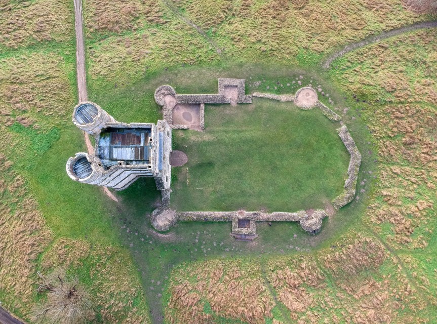
Aerial view showing the outline of the castle’s walls (Matthew Prior)
The castles walls probably enclosed a hall, kitchens, storerooms and accommodation for guests with the main quarters being in the gatehouse keep. While not an elaborate, larger or militarily complex as some other castles it still imposing sight.
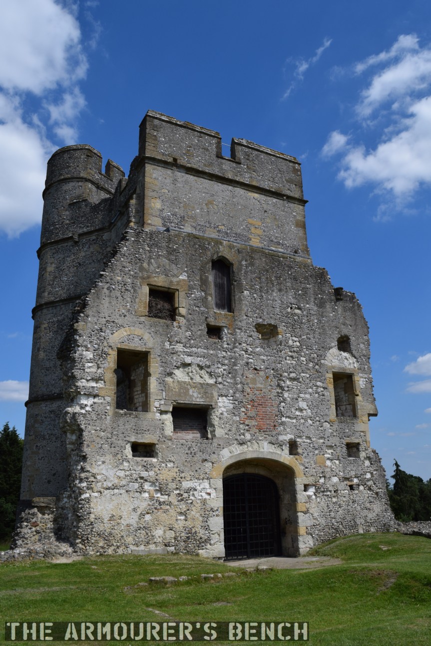
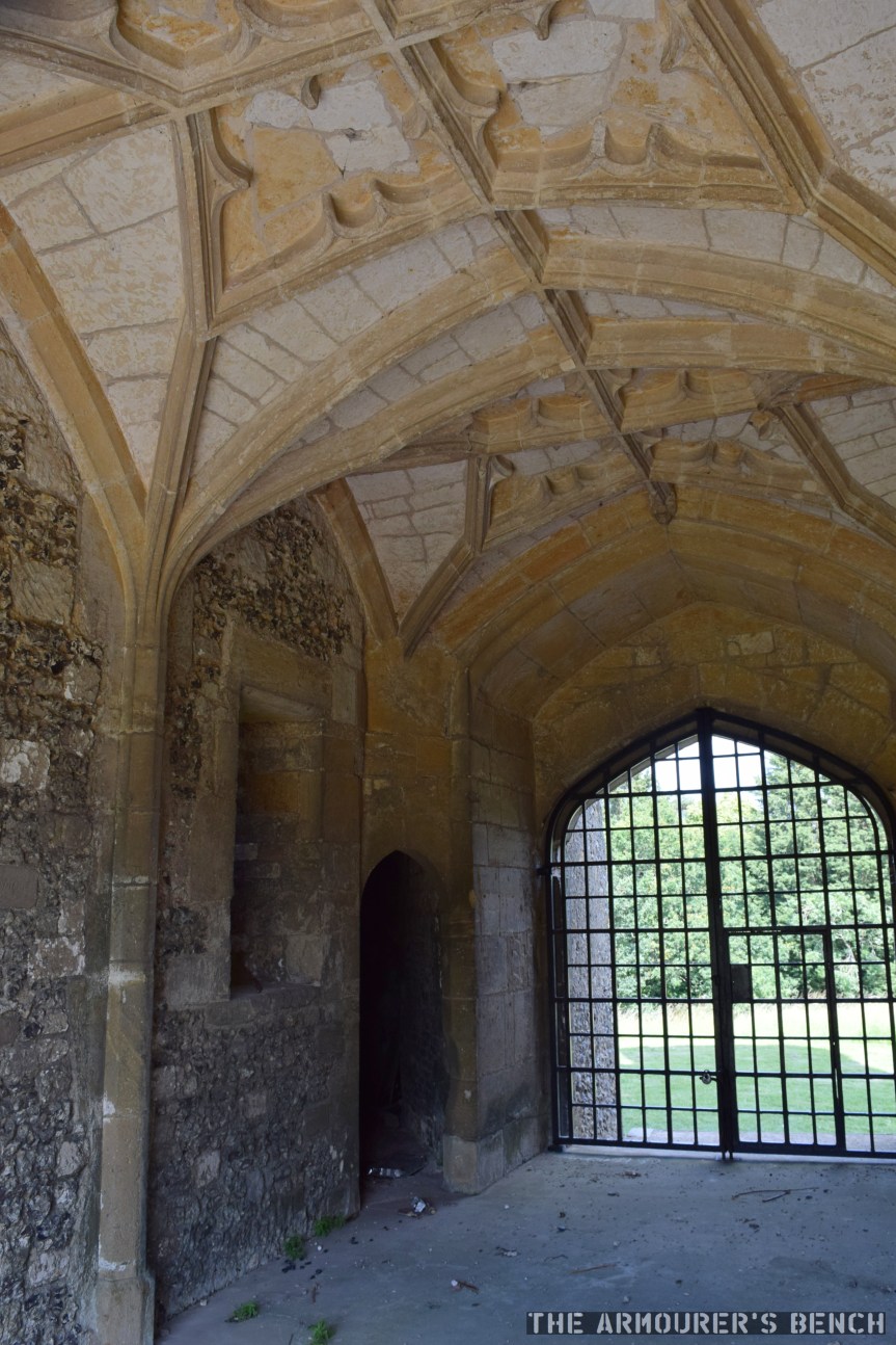
The rear of the gatehouse shows the outline of former rooms which were damaged and demolished. Note the later brick used to repair some damage (Matthew Moss)The vaulted and corniced ceiling inside the gatehouse entrance, hinting at the castle’s role as a home more than a military position (Matthew Moss)
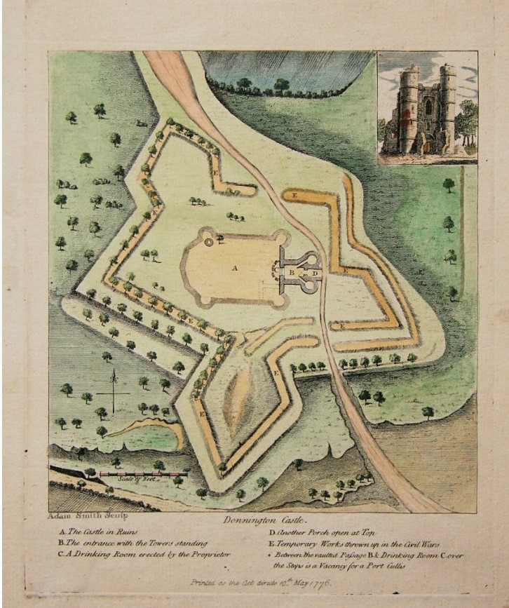
Both Henry VIII and Queen Elizabeth I visited the castle during the Tudor period. The castle didn’t see action until the 1640s and the outbreak of the English Civil Wars (1642-1651). While the castle has been owned by a Parliamentarian family, the Royalists took control of the caste in 1643 and began fortifying it. Sir John Boys set about building elaborate star-fort defences around the original medieval castle. Boys built a set of angular trace Italienne at the considerable cost of around £1,000. Donnington Castle was one of many medieval castles that saw new life during the Civil Wars. Old castles along with churches and country houses were re-purposed and hastily defended by new earthworks.
18th Century map showing outline of the castle’s Civil War defences
The castle’s new defences included four new bastions, with emplacements for cannon, ditches and a palisade wall. Royalist forces at the fort initially numbered just over 200 men and four cannon. The Second Battle of Newbury was fought within sight of the castle in October 1644 and after the battle the castle’s defences were reinforced by a number of large guns left behind by King Charles’ retreating forces.
The castle itself was attacked numerous times during the war, during the second attack on the castle part of the wall was damaged. The castle had to be and had to be relieved by Royalist forces twice the final siege in March 1646 began. The castle was badly damaged after the siege with its walls and outer towers hardest hit but remained defensible. With no hope of relief the garrison surrendered and were allowed to march out with their colours.
As with so many other castles after the war Parliament voted to demolish it and only the gatehouse was left standing. It is now a scheduled monument.
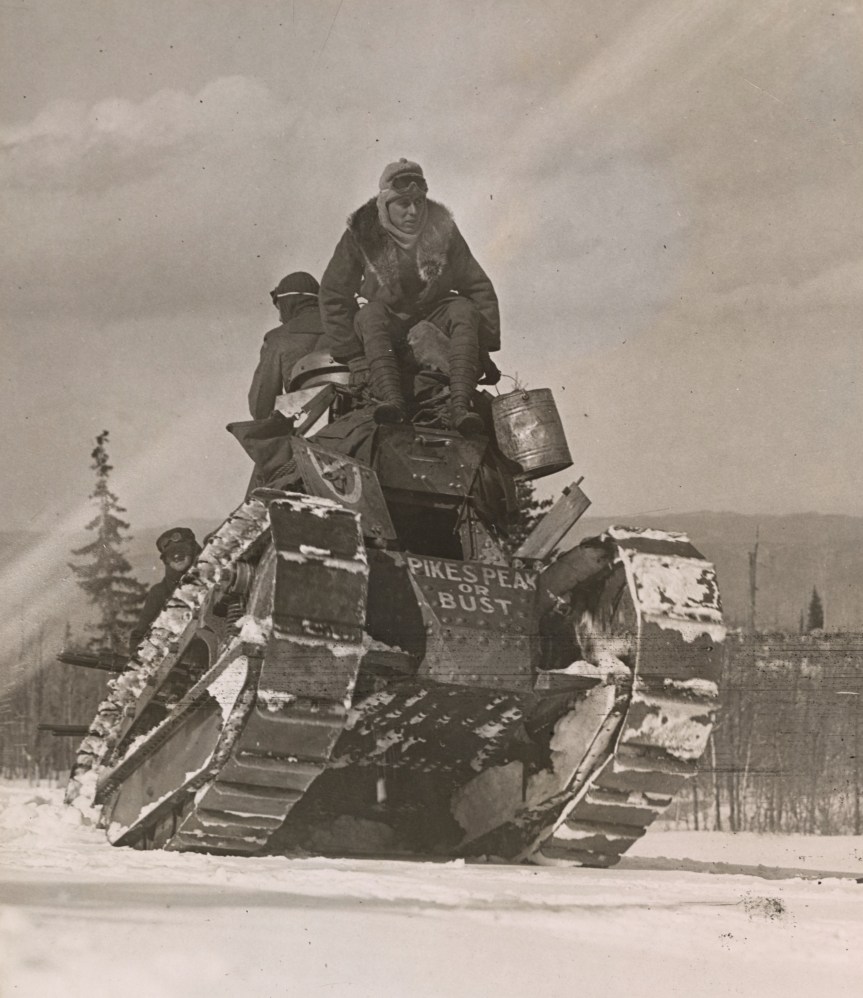
In April 1919, a lone US-built M1917 light tank climbed over 11,000 feet up a mountain in Colorado. We are lucky enough to have some original photos and footage of the tank’s climb up Pikes Peak in the Rocky Mountains.
The tank with ‘Pikes Peak or Bust’ painted on its hull (US National Archive)
Why was a tank driving up a mountain?
Simply put the expedition was a publicity stunt to help raise cash to pay off America’s war debt. By 1919 the cost of US involvement in World War One had reached $32 billion – that’s around $547 billion today.
The purpose of the stunt was to encourage Americans to purchase ‘Victory Liberty’ War Bonds which would help pay off some of the debt accrued by the war. This was the fifth, and final, round of Liberty Bond sales. The drive began in mid-April 1919, and aimed to sell $4.5 billion of government bonds.
The tank arrived in Colorado Springs at the beginning of April and on the 14th a crowd of nearly 1,000 people watched Mrs W.H.R. Stote, the chairwoman of Colorado Springs’ Victory Liberty loan committee, christened the tank ‘Little Zeb’ – after explorer Brigadier Zebulon Pike – who led an expedition that attempted to climb the mountain in 1806)
Mrs Stote reportedly declared “I charge you with making the trip to the summit. As the Victory Loan shall not fail, you must make it to the top!” The tank’s commander Sgt. A.H. Worrell, told The Colorado Springs Gazette that he had “driven tanks over trees and trenches on the western front and I am betting we get to the top.”
The road up to the summit of Pikes Peak, photographed in 1934 (US National Archive)
At the time the 19 mile road up to Pikes Peak was said to be the ‘World’s Highest Motor Drive’ with the summit at 14,115 feet (or 4,302m). Cpl. Howard Brewer, the tank’s driver told reporters “I know we can climb it. Given time, the tank could go to the top of the world.” In terms of publicity having the tank make it up the mountain would certainly have been quite a feat.
On the front of the tank’s hull the words ‘Pike’s Peak or bust’ were painted in white – this is a reference to a phrase coined by prospector’s during the Pike’s Peak Gold Rush of the 1860s.
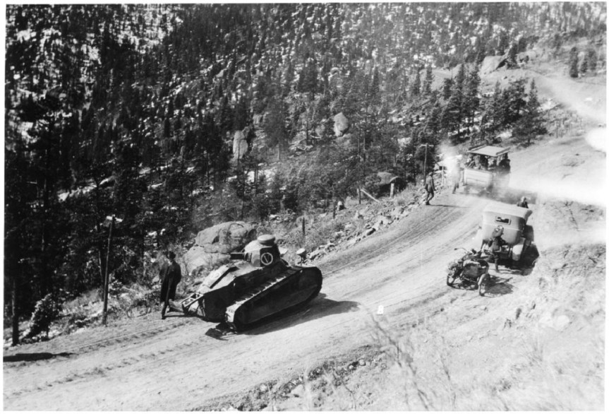
The tank on the road up Pikes Peak (Pikes Peak District Library)
The tank was driven by Corporal Howard Brewer and tended by a crew of mechanics and support vehicles. The road which climbed the mountain was unsurfaced and had only been completed in 1916. The tank’s ascent began on April 15, and incredibly over the next two days the tank climbed to 11,440 feet, 13 miles along the road and through several deep snow drifts, reportedly up to 20-feet tall, before a track plate snapped. After repairs the tank and support convoy pressed on – but the tank never made it to the summit. Not because of mechanical failure but unbelievably because it was needed to appear in other Colorado towns as part of the Victory Loan drive.
While the tank may not have reached the very top of the mountain, it unsurprisingly became a record breaker – setting the first elevation record for tanks. Western Union claimed that it also set a distance record for continuous distance travelled and penetrated the farthest into the snow than any other vehicle had ever done at that time of year – battling snow drifts up to 20 feet tall. While the US-built M1917 was never tested in battle the drive up the mountain proved it was a capable, hardy vehicle – demonstrating the tank’s abilities.
Bibliography:
Various photos and contemporary footage taken from the US National Archives (source)
Additional photos held by the The Manitou Springs Historical Society (source)
‘Army’s Tank Assault on Pikes Peak Was About More Than Being Macho’, The Gazette, M.L. Cavanaugh, (source)
U.S. Economy in World War I, Economic History Association, (source)
The Walther P5 was developed in the mid-1970s as an response to the West German police’s continued search for a 9x19mm service pistol to replace the older smaller calibre pistols then in service, like the Walther PP. It was developed to fit the new police specification for a small, handy pistol which could be brought into action quickly. Walther’s design competed against pistols from Mauser, Heckler & Koch and SIG Sauer.
Walther P38 (Rock Island Auctions)
The P5′s design evolved from the P38, combining the lock work and dual recoil springs of the P38 (re-designated the P1 in 1963) with a shortened barrel and a full length slide. While a shortened P38k had been produced in the early 1970s, this was only an as an interim solution. The P38K retained the same slide and frame as the original P38s, but had the front sight mounted on the front strap of the frame and none of the pistol’s contours were rounded to aid drawing and returning to a holster. Only around 2,600 P38Ks were produced.
Following the attack on the 1972 Munich Olympics games West German police began the search for a new service police. Walther’s response, the P5, was introduced in 1978. The P5 is a locked-breech pistol and has double-action/single-action (DA/SA) trigger. It uses the same short-recoil operated system and locking mech as the P38. This means that the barrel and slide recoil together for a short distance before the locking block falls and allows the slide to continue moving rearward, ejecting a spent case and chambering a new round.
Walther P5 (Matthew Moss)
Walther moved the P5’s decocker from the slide to the frame and this also served as the slide stop and slide release. I would say that the P5’s decocker is easier to operate, with a shorter length of travel, than the SIG P6’s.
Following the West German police specification Walther designed the pistol to be safely and rapidly brought into action, and as a result dispensed the manual safety. Instead, the pistol could be carried in condition two – with a round in the chamber and the hammer down. This was safely achieved by some upgrades to the P5’s hammer and firing pin. There is a small recess in the pistol’s hammer for the firing pin. The firing pin only moves into alignment with the hammer surface when the trigger is pulled.
The P5 has a 3.5 inch (9cm) barrel and fed from an 8-round, single stack, magazine with a heel release. Like the P38 the pistol ejects to the left rather than the right. The P5 has a stronger and more durable fully enclosed slide which is contoured to aid holstering. The pistol has an alloy frame, with full-length slide rails and an enlarged trigger guard for use with gloves.
Diagram showing the P5’s parts and internal layout (Walther)
In addition to the P5, Walther also developed a compact model for plain clothes use which had a slightly shorter barrel (3.1 inches), slide and a truncated hammer. It was introduced in 1988 and had a lighter alloy frame with the P5 Compact weighing 750g (1.65lbs) rather than 795g (1.75lbs). While early production pistols retained the heel magazine release the majority had a thumb release. A small number of P5-Lang, long barrel target pistols were also produced in the late 1980s.
Disassembly is simple and comes directly from the P38. The slide is retracted a little until the barrel catch can be rotated. The slide and barrel can then be slid forward off the frame once the trigger is pulled.
The P5 proved to be an accurate and reliable pistol and once it was accepted by the police trials (along with the designs from Heckler & Koch and SIG-Sauer – the P7 and P6 respectively.) It was adopted by uniformed officers of Baden-Württemberg and Rhineland-Palatinate’s State Police – these pistols were marked ‘BMI’ for Bundesministerium des Innern – the Federal Ministry of the Interior. This pistol is a BMI-marked gun and dates from February 1983.
Walther P5 brochure cover (Walther)
It also became the standard issue sidearm of the Dutch police who purchased around 50,000 pistols, becoming Walther’s largest customer for the P5. The Dutch guns were later fitted with aftermarket Houge rubber grips and some changes to the hammer safety system were later made in the mid-1990s. The Dutch police retired the P5 in 2013 replacing it with the P99Q.
The P5 also saw some military sales with elements of the Portuguese Army adopting it and the P5 Compact was also adopted by the British Army. Selected in the late 1980s for issue as a personal protection side arm. It was designated the Pistol L102A1 and was extensively issued to British troops in Ireland for use while in plain clothes or off duty.
The P5 on screen: Sean Connery as James Bond in, the technically unofficial, 1983 Bond movie Never Say Naver Again. Roger Moore’s Bond also carried it in Octopussy (also in 1983)
While certainly one of Walther’s lesser known pistols the P5 is a well-made, well-designed duty pistol, with comfortable ergonomics – the fiddly magazine catch not withstanding – and the slide and decocker are very smooth to operate. The trigger pull in both the single and double action modes is also pretty good. Overall, around 100,000 pistols were produced before production came to an end in 1993.
In the late 1950s the US military began development of a bomb capable of destroying deeply buried bunkers. The result was a bunker busting unguided thermonuclear bomb. Durng a visit to the Atomic Testing Museum, in Las Vegas, Matt had the chance to take a look at a decommissioned B53 up close.
B53 on display at the Atomic Testing Museum (Matthew Moss)
The B53 is a two-stage high-yield thermonuclear weapon, designed as a bunker buster, that could deliver a massive shockwave deep underground to the deepest Soviet command and control bunkers. Developed between 1958 and 1961, the B53 was intended to combat deeply emplaced Soviet bunkers with a yield of 9 megatons. It used a highly enriched uranium core as its primary fission stage with Lithium-6 deuteride as its second stage fusion element. The warhead itself was developed from the earlier Mk46 warhead, the experimental TX-53 was tested at the Pacific Proving Grounds as part of Operation HARDTACK I, which saw no less than 35 nuclear test detonations. Codenamed HARDTAK OAK, the TX-53 was detonated aboard a floating barge on 28th June 1958, with a yield of 8.9 megatons. The detonation created a cloud 78,000 feet (23.8 km) tall.
Cloud produced by HARDTACK OAK (Los Alamos National Laboratory Archive)
Designed to be dropped from the Strategic Air Command’s B-47, B-52 or B-58 bombers, the B53 is a gravity bomb which free fell to its target and could be air or surface detonated. The bomb itself weighed 8850 lbs or 4014kg and the casing is 12.5 feet long (3.8m) and just about 50in (1.27m) in diameter. The bomb’s outer-casing is split into a nose section, a two-piece central casing and the rear assembly with four fins which housed the parachute assembly. They were built by the Atomic Energy Commission between 1962 and 1965, over 340 bombs were built. Initially designated the Mk53 it was re-designated the B53 in 1968, when the US Air Force updated its ordnance nomenclature.
The bomb itself could be deployed in four ways: a delayed surface burst, a free fall air burst, a parachute retarded air burst (the B53 had five parachutes at the rear which can be deployed) or an immediate contact surface burst. Here we can see the panel to control the parachute deployment, with markings for safe, free fall and retard.
Declassified general diagram showing the assemblies of the B53 (US DoD)
The B53 was obsolete in terms of its safety by the early 1980s with none of the more modern safety features such as an Enhanced Nuclear Detonation Safety (ENDS) additionally its explosive lens, consisting of a mix of RDX and TNT was not an insensitive munition – meaning it wasn’t designed to resist detonation from external stimuli or damage. The B53 also had no Fire-Resistant Pit (which prevents the spread of radioactive material in the event of a far), Permissive Action Link (which prevent unauthorised arming) or Command Disable safety measures.
B53 at the Pantex Plant in Texas about to begin the dismantling process (National Nuclear Security Administration)
Many of the B53s in US inventory were decommissioned in the mid-1980s, and by 1987 just 50 were retained in inventory. The last of these were disassembled and decommissioned by October 2011 – after being in service for 50 years. The B53 was replaced in its bunker busting role by the smaller B61 Mod 11.
The SAR-80’s story begins in the early 1970s, when Frank Waters, the Sterling Armaments Company’s chief designer, began developing a 5.56x45mm rifle for sale to foreign militaries. While two initial prototypes were produced the project lapsed when Sterling secured a license to manufacture Eugene Stoner’s AR-18.
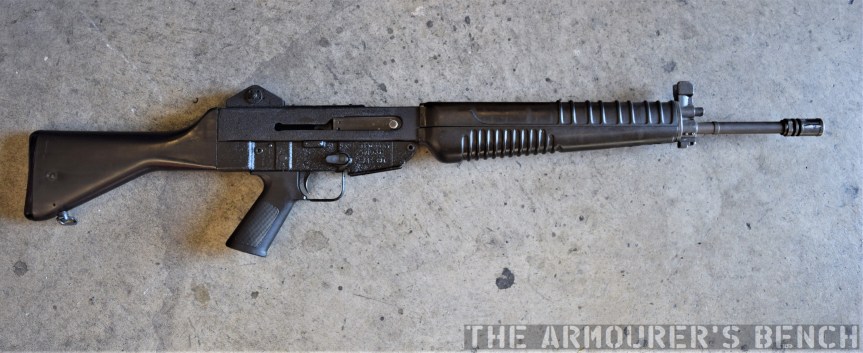
Right-profile view of the SAR 80 (Matthew Moss)
In the late 70s the project was resurrected and in February 1977, two prototypes were sent to Chartered Industries of Singapore (CIS)[later known as ST Kinetics] who had been seeking a 5.56x45mm rifle design to produce for export to sustain production at their factory. The initial prototypes reportedly suffered issues with obturation with some cartridges and Sterling engineers worked to rectify this with another batch of half a dozen prototypes being sent to CIS in late 1977. CIS produced their first pre-production prototypes in 1978, for testing by the Singapore Army. CIS opted for a plastic buttstock and redesigned the handguards too.
Factory brochure photo of Singaporean soldier with SAR 80 (CIS)
Initially described as the Sterling Light Automatic Rifle and later the Sterling Combat Rifle the rifle, however, as it finally entered production in 1979, it became known as the Singapore Assault Rifle 80 or the SAR-80. Some of the earlier rifles are also marked ‘Sterling Assault Rifle’.
The first SAR-80s were delivered to the Singapore Armed Forces in early 1981 for troop trials. Faults with these early production rifles included poor fit and finish and extractors which bent leading to extraction and ejection issues. Refinements made rectified these faults and subsequent production runs had improved reliability.
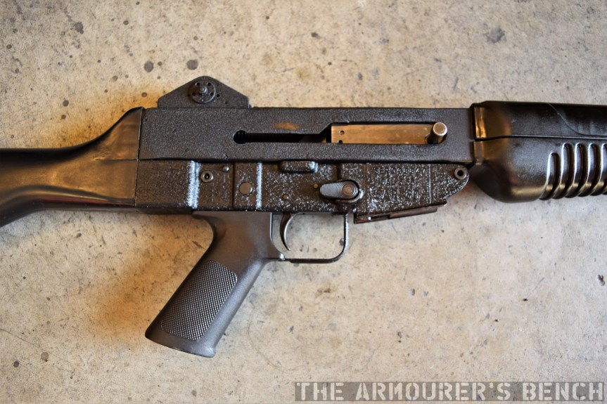
Close up of the receiver, note the sliding dust cover is missing from this rifle (Matthew Moss)
The SAR-80 can be described as a clone of the Armalite AR-18 with their internal designs almost identical. The SAR-80 is gas-operated, with a short-stroke gas piston and a rotating bolt. The bolt has 7 locking lugs, the internal mechanics of the rifle are more or less identical to that of the AR-18, using dual recoil springs and a rectangular bolt carrier. The bolt geometries differ slightly to the AR-18’s and the SAR-80 also has an additional weight inside its bolt – which adds mass and helps slow the rate of fire down to around 600rpm. Like the AR-18 its charging handle is attached directly to the bolt carrier and is reciprocating.
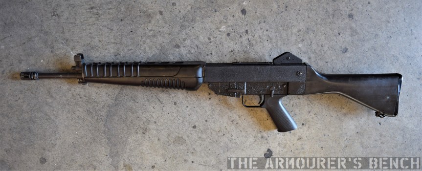
The rifle feeds from standard STANAG magazines and is select-fire, with a selector on the left side of the rifle and a magazine release on the right. The selector layout is modelled after the M16’s and the front handguard’s design was also influenced by the M16. The SAR-80 has simple stamped receiver, similar in profile to the AR-18’s, it has a crackle-paint finish, like that seen on the commercial Sterling Mk4 SMGs. It has a two-position folding rear peep sight and is 97cm (38in) long and weighs 3.7 kg (8.2 lb) unloaded.
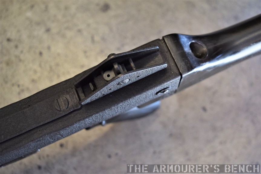
Close up of the rifle’s sights, note the rudimentary scope mounting rail (Matthew Moss)
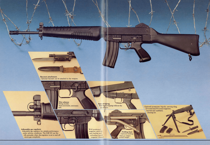
The SAR-80 had a bayonet lug just beneath its adjustable gas block and mounted an M16-pattern bayonet, other accessories included a scope mount, bipod and a blank-firing adaptor. And of course a folding stock variant was also available.
Graphic showing the rifle’s features from factory brochure (Matthew Moss)
I didn’t have a chance to strip the rifle but here you can see the hammer inside the receiver – its worth noting that this rifle does not have the sliding dust cover seen on other examples, and the charging handle slot is completely open.
Left-profile view of the SAR 80 (Matthew Moss)
Developed with cost in mind, contemporary literature from CIS state an export price of around $300 per rifle, the equivalent to day of about $930. CIS produced more than 80,000 between 1980 and 1988, it saw limited service with Singapore’s military but did enjoy some export sales, with the SAR-80 used by the Central African Republic’s Gendarmerie, the Croatian Army, the Papua New Guinea Defence Force and the Slovenian Territorial Army. CIS replaced the SAR-80 with the SR-88, a rifle co-developed with Sterling as the SAR-87, but this proved unsuccessful and has since been superseded by the SAR-21 bullpup.
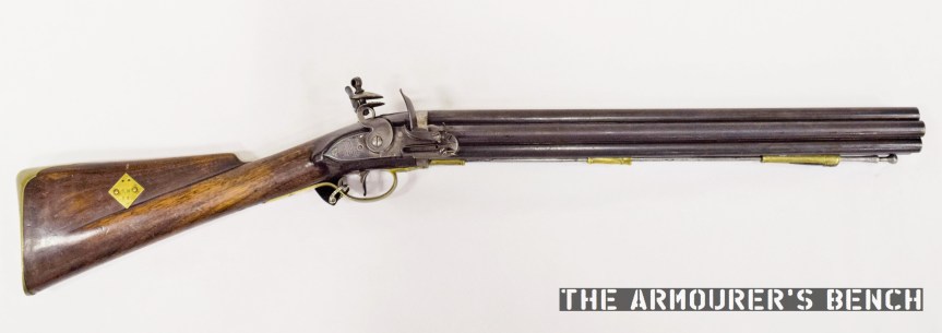
Commonly referred to as Nock Guns, the seven barrel volley guns were actually designed by James Wilson. Wilson presented his design to the Board of Ordnance for testing in July 1779. Following testing at Woolwich Arsenal the Board of Ordnance decided that the guns, while of no use to the Army, might be useful aboard the Royal Navy’s ships. The volley gun’s impressive firepower could be devastating at the relatively short ranges aboard ships. The Navy had historically used blunderbusses/musketoons and the Board of Ordnance probably viewed Wilson’s gun as an advancement of this concept. London gunmaker Henry Nock was given an order for two ‘seven barrelled rifle guns’ for Admiralty testing but these proved slow to load in action and subsequent guns had smoothbore barrels.
Right-side profile of the volley gun (Matthew Moss)
The Admiralty envisioned equipping first rate ships of the line (vessels with 75 guns or more) with 20 volley guns, while second and third rates would have 16 and 12 volley guns respectively, and frigates would carry 10 Nock guns. This represented a sizeable order. The Admiralty eventually purchased 500 guns, paying £13 per gun, to equip Royal Marines and sailors manning the fighting tops (at the top of ship’s masts). The Navy felt that the volley guns’ firepower would be useful when boarding enemy vessels or in repelling boarders by pouring down fire on enemy boarding parties.
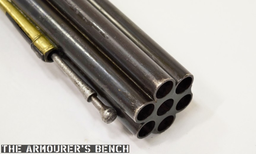
A close up of the gun’s muzzel-end, not also the ramrod which appears to have been lengthened at some point in its life (Matthew Moss)
Henry Nock, better known for producing high quality duelling pistols and sporting guns, became the sole supplier of Wilson’s volley guns to the Royal Navy. The weapon’s 0.46 inch calibre outer barrels were arranged around the seventh centre barrel. The 51cm or 20in barrels were brazed together and screwed to an iron plate set into a walnut stock. The outer barrels had vents drilled through them to the central barrel while the central barrel had a vent leading from the lock. Once the flintlock ignited the powder charge in the central barrel, the surrounding barrels were ignited through the vents. As the vents had to be drilled with the barrels already brazed into position, the outer barrels all have plugged drill holes on their outer surfaces.
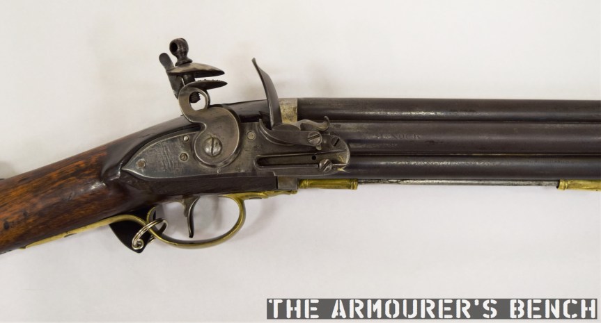
A close up of the lock and the ‘H. NOCK’ makers mark (Matthew Moss)
All seven barrels fired almost at once producing significant recoil, reputedly able to dislocate shoulders. The service load was originally 2.5 drams of finer rifle powder (which I believe equals 68gr) for each barrel – totalling 476gr. Despite the gun weighing 12lbs, this did little to mitigate the weapon’s recoil and a reduced charge or 1.5 drams of standard musket powder was ordered.
The Board of Ordnance and the Admiralty granted Wilson an awarded of £400 (equal to £48,000 or $63,000 today) in May 1780. He played no further role in the testing and development of the volley gun. In 1787 the Navy ordered a further 100 guns from Nock.
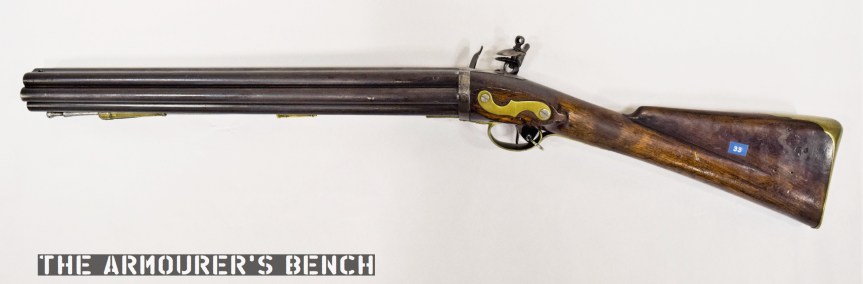
Left-side profile of the Nock Gun (Matthew Moss)
Entering service just too late for service during the American War of Independence the first reported use of the guns came with Admiral Howe’s fleet at the siege of Gibraltar in 1782. They continued to be carried aboard other vessels during the 1790s, but few accounts refer to them and little is known about their service.
Howard Blackmore suggests that naval officers, including Admiral Nelson who disliked placing marksmen in his tops, disliked the guns. There were some fears that the volley guns’ wads could set the ships sails and rigging on fire. Reputedly it was also not uncommon for some of the volley gun’s barrels to fail to ignite. As a result the guns were seldom used on board ships and removed from Royal Navy service in 1804. In 1805, Wilson, then a captain of the Marines suggested the Navy reissue the guns to the Sea Fencibles, a naval militia which helped defend the British coast, however, his recommendation was not followed up.
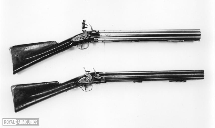
The early (top) and later (bottom) patterns of Nock volley gun (Royal Armouries)
This particular example has the second pattern of lock used on the Nock guns with a smaller lock positioned a little lower on the gun. The earlier pattern was a back action lock, fitted high on the gun with the front of the lock plate in line with the side of the barrel.
The gun has a maker’s mark of ‘H. NOCK’ on the second barrel on the left and various barrel proof marks. Unlike other examples the lock itself isn’t Tower and ‘GR’/Crown cypher marked but does have the Ordnance Broad Arrow just behind the pan. Interestingly, the steel ramrod appears to have an extension brazed onto the end of it, this might indicate that the shorter rod used with the initial charge had to be extended when less powder was used for the lighter 1.5 dram load.
Why did the Nock Volley Guns fall out of favour?
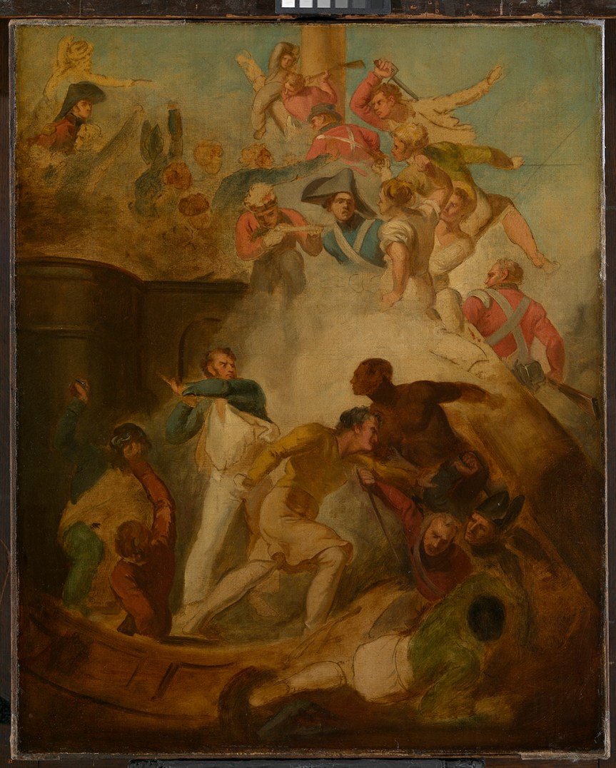
As I mentioned earlier the recoil of the initial service load was significant, Howard Blackmore hypothesised that there may have also been some weakness to the lock springs leading to misfires. One key factor is that close quarters fighting aboard ships often relied on edged weapons like cutlasses, boarding axes and pikes. These paintings give us some feel for what fighting aboard a Napoleonic Man-of-War might have been like – a close, chaotic, terrifying affair.
Boarding Party by D. Drummond, (National Maritime Museum)
While pistols were commonly used they were disposable and may not have been reloaded during a fight – more likely they were dropped or used as a club. The Nock Gun would have offered a devastating first volley, and while its 20 inch barrels would have given it better accuracy and range than a musketoon, how much of an impact a single volley of seven .32 bore projectiles would have had especially once the fighting became hand to hand is a matter for debate. At close quarters the Nock Gun quickly becomes a short, ill-balanced, 12lb club.
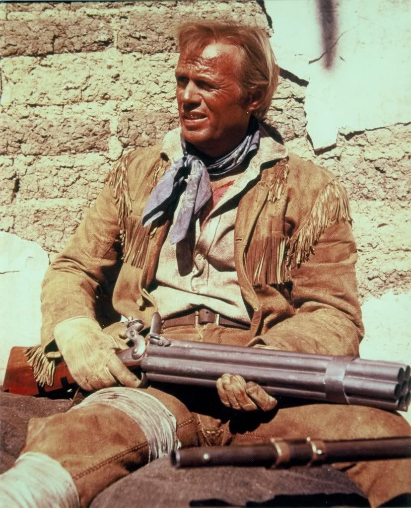
The Nock Volley Gun is perhaps best known for appearing in the Sharpe series of books and films as Sergeant Harper’s weapon of choice but it first appears on screen in the 1960 classic The Alamo with Richard Widmark’s Jim Bowie carrying one and more recently a fleeting, anachronistic, appearance in Master & Commander: Far Side of the World.
Richard Widmark as Jim Bowie in The Alamo (1960) with his pretty rough mocked-up Nock Gun
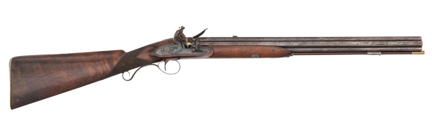
Despite a relatively short and undistinguished service life the Nock Volley Guns also saw some civilian sales with a number of ornate hunting guns with wooden forends, engraving, rifling and rear leaf sights.
A civilian Nock Volley Gun, note the rear sights, wooden forend and fine craftsmanship (Cowan’s Auctions)
Later in 1818, Nock’s workshop manufactured a design by Artemus Wheeler, an American gun designer with a fondness for revolving guns.
Wheeler’s carbine resembles the earlier volley gun externally but is in fact a manually rotated, self-priming flintlock ‘pepperbox gun’ with six barrels arranged around a central axis. Unlike the earlier volley gun the pepperbox carbine was never trailed or purchased by the Admiralty. Henry Nock’s workshops produced approximately 655 volley guns between 1780 and 1788. The Nock Gun is a weapon that would greatly benefit from some in-depth contemporary research as the current best source is over 50 years old and relatively little is known about the gun’s service history.
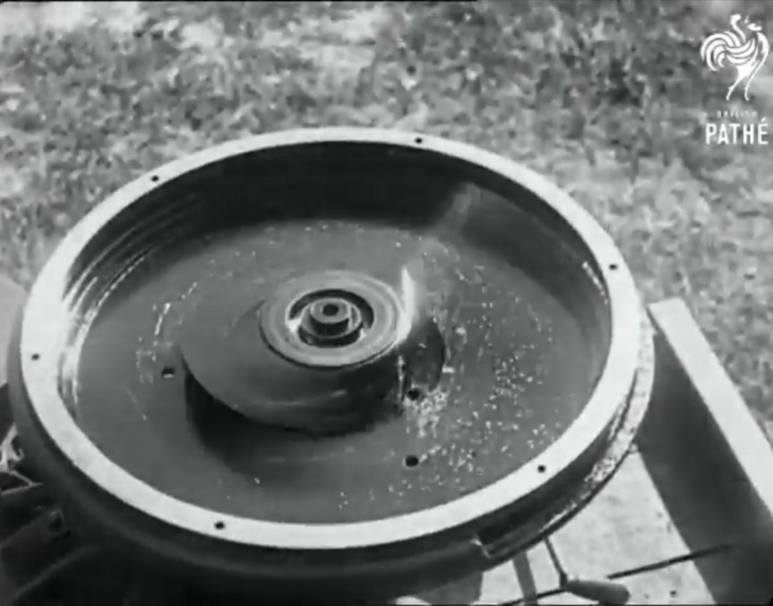
Today, we’re going to take a look at a little known type of weapon which rose to prominence in around the time of the First World War with a number of examples being developed and some even tested. As you can see from this footage it’s something pretty unconventional, seen here mounted on the back of a truck – is a centrifugal machine gun.
I found this short footage while doing some digging through the online catalogue of the US National Archives. The centrifugal machine gun was not a new concept by the time this footage was filmed in the early 1920s, sadly the footage notes done give an exact date.
A still from footage of the demonstration (US National Archives)
While the technology had risen to a new prominence what was the allure of centrifugal machine guns? The principle of centrifugal force – an inertial force which appears to act on objects moving in a circular path, directs them away from the axis of rotation. As a result a centrifugal machine gun required no propellant powder to propel the projectile, or a case to contain it, nor a conventional rifled barrel to stabilise the projectile. Once released from the axis of rotation the projectile travels on a linear trajectory until it expends its energy. It works along the same principle as a primitive sling. The primary issue is providing power to exert the centrifugal force and a means of accurately firing the projectiles.
Some of the earliest work on centrifugal guns was done in the late 1850s in the US. The hand-crank or steam powered guns patented by William Joslin (US #24,031), C.B. Thayer patent for a ‘machine gun’ in August 1858 (US #21,109) and Charles S. Dickinson (US# 24,997) in 1859. Dickinson went on to secure financial backing from a wealthy Maryland industrialist Ross Winans and developed a steam powered version of his gun. Despite gaining much press attention Dickinson’s centrifugal gun saw no action during the US Civil War. In 1862 G.C. Eaton and S.W. Turner also patented a ‘machine gun’ (US #37,159).
An illustration of the Winans Steam Gun, Frank Leslie’s Illustrated Newspaper, May 1861
It wasn’t until World War One that the concept began to be considered again. In June 1918, Major Edward T. Moore and Saul Singer filed a patent for a centrifugal machine gun powered by an electrical motor (US #1,332,992). The motor spooled up the centrifugal barrel assembly to rotate extremely quickly and impart centrifugal force on projectiles. According to Julian Hatcher the gun could fire steel ball bearing projectiles at approximately 1,200 feet per second. Fire was controlled by a stop pin in the ammunition feed tube. Moore claimed the weapon could fire a projectile 1.5 miles with enough force to kill a man. He also suggested the weapon’s rate of fire approached 2,000 rounds per minute. It appears that Moore’s gun may have been tested in 1918 but Hatcher described its accuracy as ‘extremely poor’.
Photograph of Moore’s gun during testing (Hatcher)
Another centrifugal design developed during World War One was E.L. Rice’s half-inch centrifugal gun, sadly I’ve been unable to find any photographs or drawings of Rice’s design but the weapon was submitted to the US National Research Council in 1917. The NRC’s 1919 report states that the gun had been further developed by the NRC’s Physics Division in Pittsburgh but work had been slowed by “a common defect which has been difficult to eliminate”. Despite what the report described as ‘considerable headway’ the weapon was subsequently abandoned amid some controversy about credit for the design.
There seems to have been something of a centrifugal machine gun craze with several more patents filed between 1917 and 1926. A Scientific American article from March 1918, even noted that “every so often the daily press becomes enthused over a new centrifugal gun.”
One of the earliest patents granted appear to have been for a design by E.E. Porter, granted in January 1917. This was followed in July 1919 by inventor, Herbert A. Bullard being granted a patent (US #1,311,492) on a design which fired a disc rather than a ball. At the same time T.A. Gannoe was granted a patent (US #1,309,129) for a large, complex looking gun shown mounted on a pedestal.
In 1920, F.R. Barnes (US #1,327,518) and W.W. Case (US #1,357,028) were also granted patents which had been filed in 1917. In late 1921, Levi Lombard was granted a patent he had filed in March 1918, his gun even appeared in Scientific American. It appears to be notably smaller than Moore’s gun and has a spade grip for aiming. This was followed in 1923, by an interesting patent from Joseph T. McNaier for a centrifugal gun that could be powered by an electric or petrol engine, some of the patent diagrams show how the gun might be placed in an armoured car or aeroplane (US #1,472,080). Intriguingly, McNaier and Moore appear to have known each other quite well and were partners in a law firm together.
Here’s a gallery of some of the various patents mentioned above, not all are as detailed or as advanced as others:
The question is which of these guns is featured in the footage. The most likely bets are the Moore or the Czegka. Sadly, with only a side view and just 18 seconds of footage we don’t have much to go on. The accompanying reel notes, describing what is seen in each section of the film, describes the gun as being in the “experimental stages only” and that the prototype seen here “is intended for use as aircraft armament, for tanks and for landing parties of the Front line trenches.”
Sadly, we don’t get to see how the gun works but we can see the operator feeding the ball bearing projectiles into the hopper which has a powered feed system – he empties two cylindrical containers of balls into it one after another. It is unclear how many rounds might be in the containers, perhaps 50 each. The gun and its motor are mounted on a truck bed with a soldier in uniform, possibly aiming the weapon via a tiller.
Another of the later designs dating from the period came from Victor Czegka, a US Marine Corps Technical Sergeant, who is perhaps best known as the supply officer of Admiral Richard Byrd’s first two expeditions to the Antarctic. Czegka was granted a patent for a centrifugal machine gun in January 1922 (US #1,404,378).
Czegka’s 1922 patent (US Patent Office)
With some further digging I managed to find several articles referring to the gun in the US Army Ordnance Journal. Interestingly, a photo from the same demonstration is printed in one article, from late October 1920, with the caption confirming the man loading the weapon is the inventor, however, he isn’t named. The footage was filmed during the Second Annual Meeting of the US Army Ordnance Association. Another article dating from May 1921, also notes that the tests took place at Aberdeen Proving Ground, with the gun firing at 16,000 revolutions per minute which required 98 horsepower from the engine powering it. The gun apparently needed a “very rapid increase in power required for operation” when the speed of its revolutions was increased incrementally from 12,000 to 16,000 rpm. The article concluded that “a horsepower above 100 would have no material effect in increasing the speed” suggesting that a much more powerful, and therefore larger, engine would be needed to increase the revolution rate.
While researching I came across this set of images from a March 1922 edition of Popular Mechanics showing an unnamed centrifugal gun set up on a truck, powered by an engine on the truck bed. From the images it appears to be a gun similar to Moore’s with a single rotating ‘barrel’. The captions also note that the photographs were taken in New Jersey and Moore was a Major with the New Jersey National Guard, which may also indicate the gun is Moore’s.
Despite various designs seeing some US military testing none were ever adopted and relatively little information on them is available. It seems that they were relatively cumbersome weapons with extremely varying accuracy but this footage at least proves the concept. A short report in a may 1921 edition of Scientific American may shed some light, stating an unnamed gun was rejected “because of its great weight and its inability to obtain high initial velocity” concluding that “no centrifugal gun can have military value”. It appears that the range of the centrifugal guns was limited to the speed of their revolution, which in turn was limited by the power of the engine and motor that powered them. The larger the motor, the more cumbersome the weapon system was.
There are very few photos of centrifugal machine guns so stumbling across actual footage of one guns actually operating is very exciting. They are a fascinating tangent to the history of the machine gun – one that occasionally still garners interest.
Update
A viewer shared a Pathe Newsreel with us which included more footage from the same demonstration. The footage title suggests it dates from 1938, however, I believe this to be incorrect.
Despite the incorrect date the footage shows us the internals of the centrifugal gun and its aiming mechanism!
Here are few screen captures from the footage:
The gun’s hopper being loaded (Pathe)A front view of the weapon, showing the slit from which projectiles fired through, and a better look at the operator’s face (Pathe)The gun with its top cover and feed system removed showing the centrifugal barrel spinning up – a info card from the footage suggests it is spinning at 12,000 rpm (Pathe)
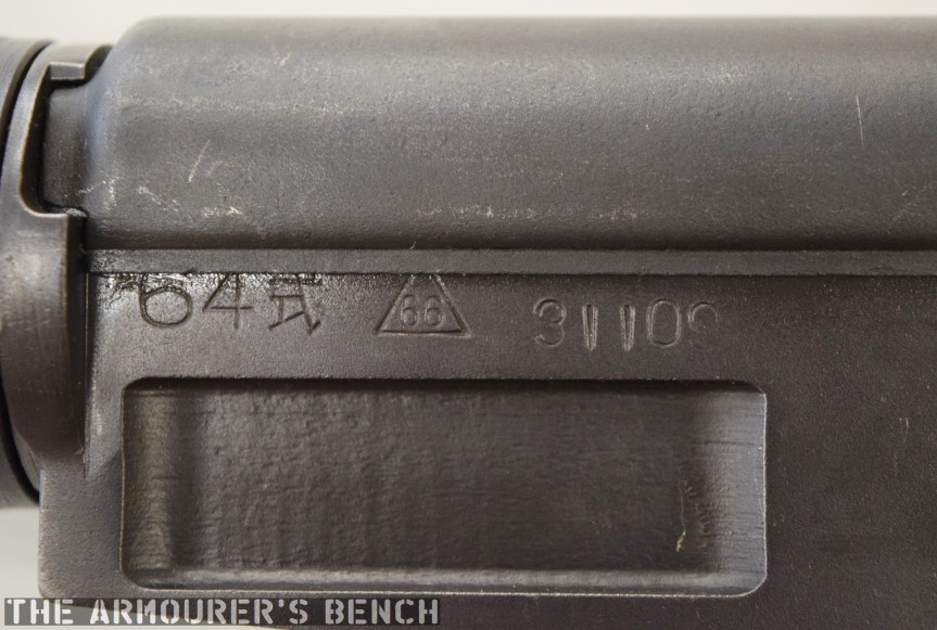
The Type 64 is an integrally suppressed submachine gun designed in China in the early 1960s, taking several design elements from other Combloc small arms. The guns were manufactured at one of China’s State Factories (with the factory’s ‘66’ in a triangle marking in the left side of the receiver – this indicates the factory number, although available sources differ on which it refers to, either 66, 626 or 366).
Right side of the Type 64, with stock folded (Matthew Moss)
Designed concurrently with the Type 64 suppressed pistol during the 1960s, the Type 64 SMG was developed for Communist China’s special forces for use in clandestine operations. Chambered in the standard 7.62×25 ComBloc pistol round, the Type 64 functioned best with Type 64 subsonic ammunition, a special subsonic spitzer projectile variation of the standard 7.62mm pistol round. It did not chamber the low power 7.65x17mm round used by the Type 64/67 pistols.
A close up of the weapon’s markings, including the State Factory 66 stamping (Matthew Moss)
The Type 64 fed from 20 or 30 round double stack magazines which were reportedly developed from or at least influenced by the Soviet PPS-43’s double stack, double feed magazines. The weapon used a conventional blowback action and fired from an open bolt. Its maximum effective range was approximately 200 metres with two position flip up sights ranging out at 100 and 200 metres.
The Type 64 had a milled receiver with lightening cuts and weighed in at 7.6lb or 3.5kg unloaded. It took its bolt from the Russian PPS-43 submachine gun and a trigger group inspired by the ZB vz.26 light machine gun’s, which was well liked by the Chinese military.
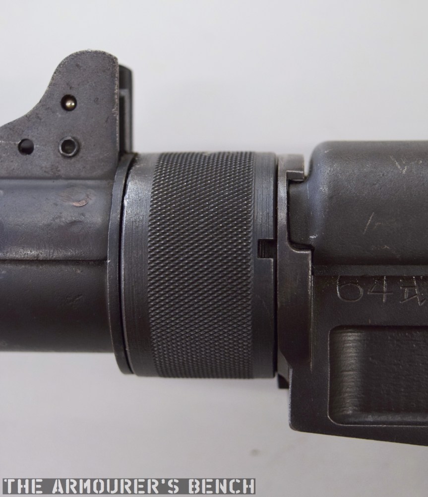
The suppressor housing is unscrewed at the trunnion with an interrupted thread (Matthew Moss)
The Type 64 shared a number of external similarities with the standard Type 56 AK-clone including its pistol grip, safety lever and under-folding stock (which is similar but slightly different to the Type 56-I’s under-folding stock).
The Type 64’s fire selector (Matthew Moss)
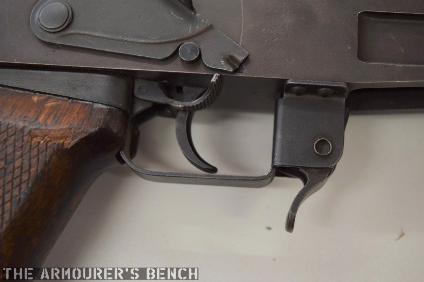
The weapon has a number different controls including a conventional AK-style safety-come-dust cover, on the right side of the receiver – which blocks the travel of the bolt. On the opposite side of the receiver it has a two-position fire selector for semi and full-auto – you can just about reach these when the stock is folded. The forward position is for semi and the rearward position is full-auto. Finally, the 64 also has an additional trigger block safety, taken from the SKS, which pivots forward to prevent the trigger from being pulled.
A close up of the magazine release, trigger block safety and lever safety (Matthew Moss)
According to a report written in October 1971, by the Small Arms Systems Lab of the US Army Weapons Command Research and Engineering Directorate, the weapon has an extremely high rate of fire of over 1,300 rpm.
A cyclic rate that high was the result of a combination of back pressure from the suppressor, the ammunition used and its blowback action. The Type 64’s chamber was fluted with three longitudinal cuts to aid extraction at its high rates of fire. It should be noted, however, that the 1971 US army tests were carried out with standard velocity ammunition – rather than the specialised subsonic Type 64.
The Type 64 with stock deployed, left & right profiles (Matthew Moss)
The top cover is removed by pushing in what at first appears to be a spring-loaded detent, but is actually the recoil spring guide rod. The front of the top cover is held in the receiver by a lip which fits into a slot just above the breech. The top cover itself is a thin piece of stamped sheet metal with the serial number stamped at the rear.
With the receiver cover removed and the action cocked. The Type 64 fires from an open bolt. Note the buffer at the rear of the receiver (Matthew Moss)
With the top cover removed we can see inside the action. The 64 has a single recoil spring held in place by a guide rod. At the rear of the receiver is a small plastic buffer, designed to both soak up some of the recoil energy and to help reduce action cycling noise. There is an ejector on the left side of the receiver and guide rails along which the bolt moves. To remove the bolt it is pulled fully to the rear and then tilt it upwards.
A close up of the bolt face (Matthew Moss)
The Type 64 is a pretty compact weapon despite the length of its suppressor. It has an under-folding stock, with two spring-loaded buttons at the rear of the receiver which have to be pushed in to fold and unfold the stock. When folded the weapon is 25in (or 63.5cm) long, with the stock adding 8 inches when it is deployed. The weapon can be used with the stock folded, although some of its controls are partially obscured.
The suppressor is contained by a housing which attaches to the receiver by an interrupted thread. The Type 64’s barrel was ported with 36, 3mm vents at the muzzle-end while the suppressor has 12 metal dished baffles held captive on a pair of guide rods. The weapon’s sights are mounted on the suppressor housing which attaches to the receiver by an interrupted thread. Sadly, I didn’t have time to strip the suppressor itself but the photos below, from my friend Chuck over at Gunlab, show the Type 64’s ported barrel and baffles well.
With the suppressor housing and baffle system removed. Note the series of holes in the barrel (GunLab)
The 1971 Small Arms Systems Lab report found that the audible report of the gun, was 150db at the rear of the receiver and 157db 12 feet down range, however, this is probably not the best indication of the Type 64’s capabilities as the report states that the gun was tested with Chinese Type 51 standard velocity 7.62x25mm ammunition. Ideally, the weapon would have been used with subsonic Type 64 ammo specially developed for China’s suppressed pistol-calibre weapons. Chinese sources reportedly put the weapons noise level at 84db when using subsonic ammunition. The US report did note that while its noise suppression wasn’t outstanding, it very effectively hid its muzzle flash.
The baffle system held together a pair of guide rods (GunLab)
It appears to have been primarily used by Chinese scouts and special forces and saw action during the 1979 Sino-Vietnamese War. In the late 80s the Chinese replaced the Type 64 with the suppressed version of the Type 85 submachine gun, also chambered in 7.62x25mm, which used the same magazines, the Type 85 had a tube metal and stamped receiver which was simpler to manufacture than the 64’s machined receiver. The Type 85 has subsequently been superseded by guns like the bullpup Type 05.
Special thanks to the collection that holds this weapon for allowing me to take a look at it. As always guys thank you for watching. If you enjoyed the video please share it with friends and help us
‘Technical Notes: Chinese Communist 7.62mm Type 64, Silenced Submachine Gun’, US Army Weapons Command Research & Engineering Directorate Small Arms Systems Laboratory, J.J. Boccarossa, 27/09/1971
Secondary Sources:
Chinese Type 64 SMG, Small Arms Review, F. Iannamico (source)
Type 64 submachine gun (PR China), Modern Firearms, (source)
Chinese Type 64 suppressed SMG, ForgottenWeapons.com (source)
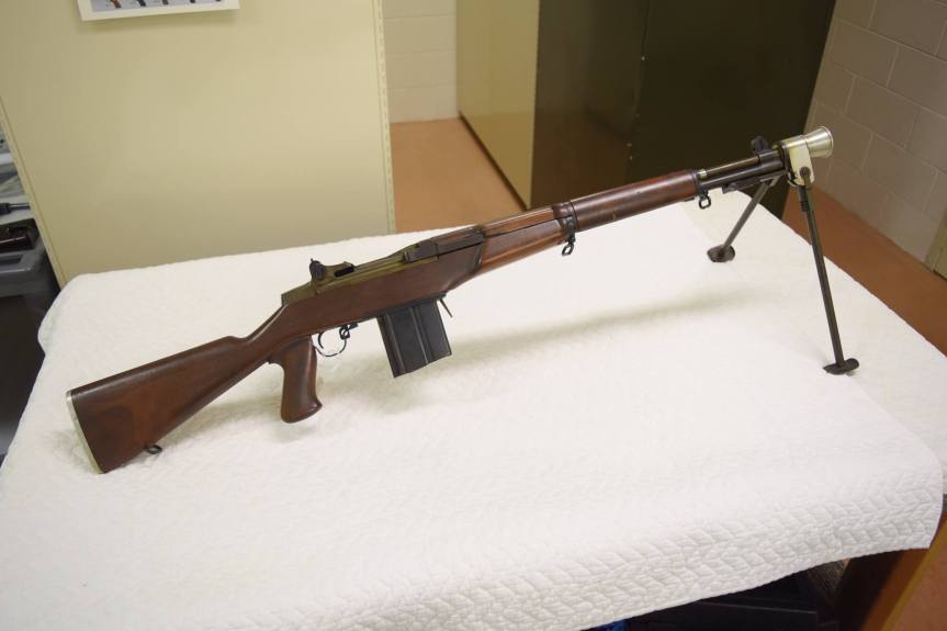
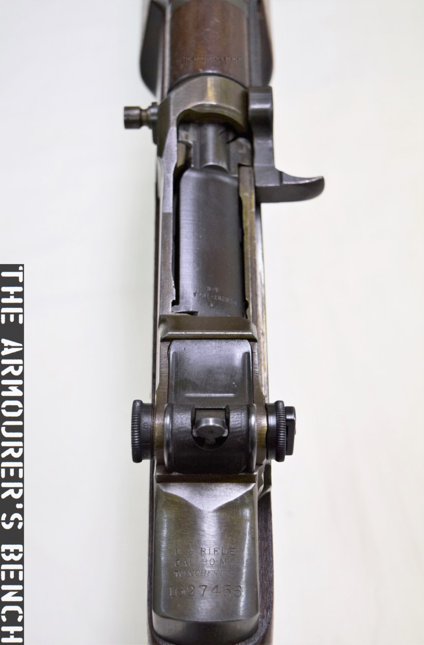
The Cody Firearms Museum, at the Buffalo Bill Centre of the West, holds a number of interesting select-fire M1 Garand rifles, adapted by Winchester during the 1940s. In this article we’re going to examine one of the prototypes, the rifle is believed to date to the late 1940s, and appears to be chambered in one of the earlier iterations of the T65 .30 Light Rifle round, which would eventually be adopted as 7.62x51mm.
Very little information is available about the rifle and little has been written about it previously. It is believed to have been developed by Winchester engineer Harry H. Sefried II with former Cody Firearms Museum curator Herbert Houze crediting Sefried with the rifle, which he described as adaptation of the M1 into a ‘squad automatic rifle’. After some archival research and combing Winchester’s patents from the period we can now attempt to shed light on a little more of the rifle’s history.
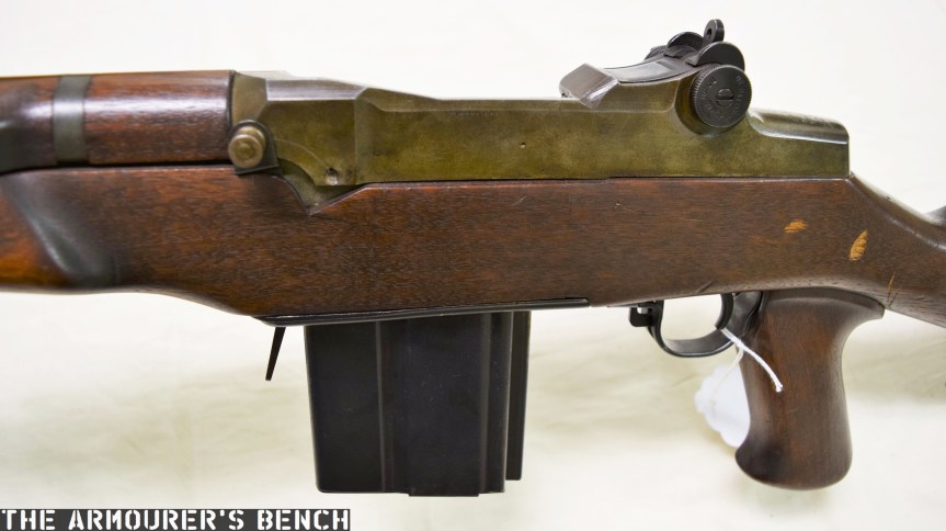
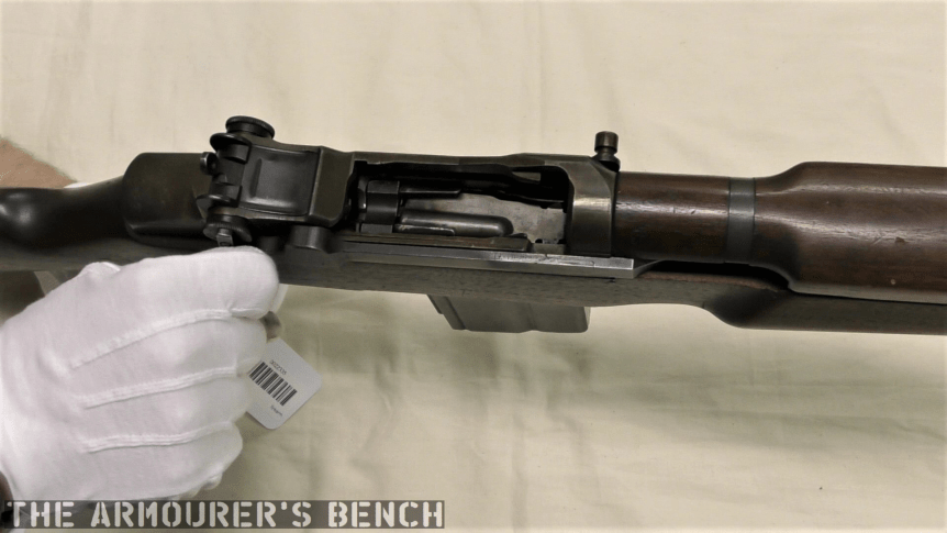
Externally, the rifle has a number of instantly recognisable distinctions from the standard M1 Garand. It has a reshaped stock with an added pistol grip, a proprietary box magazine and a combined bipod and conical flash hider. If we look closer we’ll notice that the stock has a swell just ahead of the breech, flaring out in an almost triangular bulge. These changes to the stock also distinguish this rifle from Winchester’s other select-fire M1 adaptations, which retain the standard Garand stock profile.
From the patents available combined with an examination of the rifle we can learn a lot. We cannot rely on patents to tell the whole story of the rifle, however, as many of the elements that make up the weapon appear to have gone unpatented. The substantial external and internal changes made to the rifle suggest that this was not an attempt to adapt the M1 with a minimal number of component parts changes but rather an effort to generally improve the rifle, making it conducive to fully automatic fire.
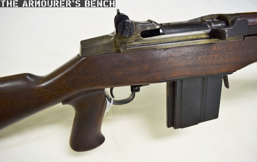
Detail photo showing the rifle’s pistol grip, altered stock and magazine (Matthew Moss)
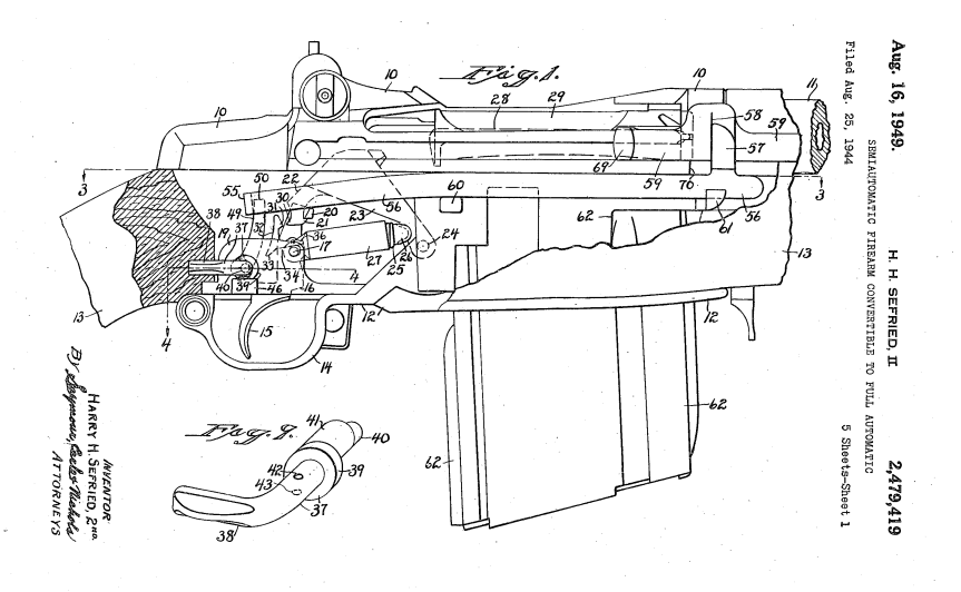
In summer 1944, Winchester’s CEO Edwin Pugsley directed Sefried to begin work on a select-fire conversion for the M1, to rival those being developed at Springfield Armory and Remington. Winchester’s select-fire Garand went though a number of iterations which resulted in two patents from Sefried. The first, filed in August 1944 (US #2479419), incorporated an elongated sear actuating lever and a selector on the lower, right side of the receiver. Winchester’s first attempts at a select-fire M1 conversion resulted in rifles with extremely high, uncontrollable rates of fire of over 900 rounds per minute. Sefried filed a second patent later in January 1948 (US #2464418) which used a catch to hook the sear. The rifle we are examining appears to have yet another select-fire system, one for which I have so far been unable to find a corresponding patent for. Winchester’s work on the select-fire adaptation came to a halt with the end of the war. It appears, however, that Winchester again began to work on adapting the M1 in the late 1940s, with Sefried again working on the project, filing his second select-fire mechanism patent in 1948 (US #2464418).
Sefried’s 1949 patent for another select-fire M1 conversion (US Patent Office)
The rifle’s receiver was originally a standard Winchester-made .30-06 M1 with a serial number of 1,627,456. This means its wartime production gun, dating from May 1945. It would appear that rather than the rifle being lifted from the rack finished, it seems that it was earmarked for prototype development because the receiver forging lacks the cuts/forgings needed for the en bloc clip release lever. This makes sense if it was known that the receiver was destined for use in a prototype which fed from a box magazine. However, the timeline of the rifle gets more complex when we consider that it was a late-war production rifle. There are a number of possibilities. The rifle may have been simply set aside for internal prototype work in May 1945 and not used until a T65 chambered rifle was developed later. Alternatively, it is possible that the rifle was converted during the initial attempts to create a select-fire M1 but was later rechambered from .30-06 to the new developmental T65 round.
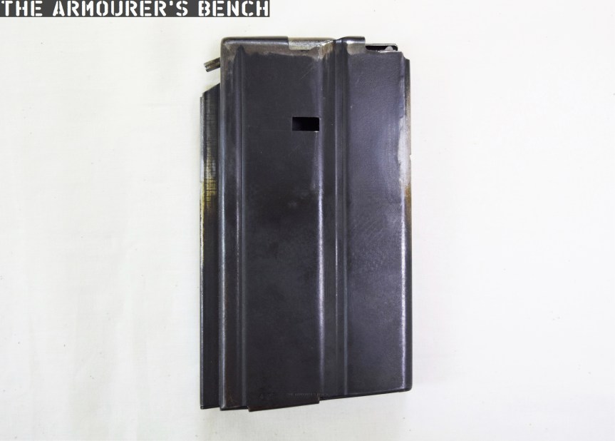
This prototype’s trigger guard assembly, which also comprises the magazine well floorplate, is a self-contained assembly and does not interact with the weapon’s trigger mechanism or action. While Sefried had a patent for his own magazine system (US #2386722) this rifle uses a slightly different magazine release and floorplate, which is similar to one seen in Stefan Janson’s 1956 patent for a stripper clip-loading box magazine for the M1 (US #2894350). The magazine used in this prototype, however, is not the same as Janson’s. It has fixed feed-lips and a projection at its rear which appears to house an anti-tilt tab for the follower.
The rifle’s magazine (Matthew Moss)
The rifle does not to appear to use the full-automatic system seen in either of Sefried’s patents. Similarly, the safety selector is located on the left side of the receiver, forward, in line with the breech. It has two positions with an arc of about 90 degrees. This position does not match Sefried’s patents for select-fire conversion, however, it does match the position patented by David Marshall Williams but not Williams’ selector’s orientation of travel. I have been unable to find a patent which matches this rifle’s selector or method fully-automatic conversion.
Left-side view of the rifle’s receiver showing the fire-selector (Matthew Moss)
The pistol grip is an interesting addition as neither of the other Winchester select-fire prototypes nor the original select-fire Springfield prototypes incorporated one. Visually it is very similar to that seen on the later Italian Beretta BM 59 Mark II. In an effort to lighten the rifle the prototype also has an aluminium buttplate. One of ingenious internal changes is the milling of the bottom of the barrel flat, this not only has the effect of lightening the rifle but also allows a new, straight operating rod to travel rearwards under the barrel. How this impacted on the barrel’s harmonics is unclear. The rifle certainly feels lighter and handier (when unloaded) than you would expect, weight is estimated to be around 7 or 8 lbs.
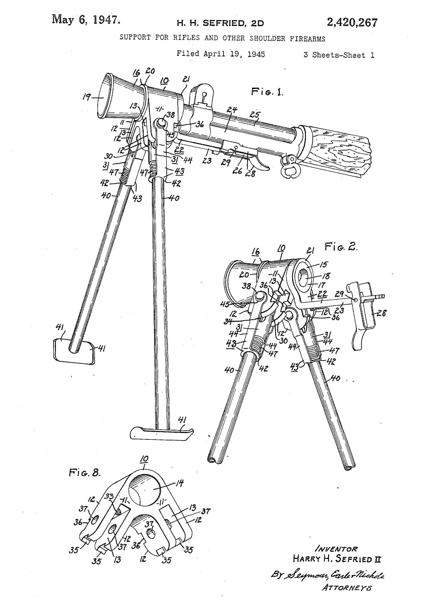
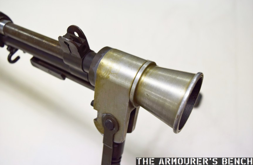
The bipod, patented by Sefried in April 1945, (US #2420267) comprises a pair of tube steel legs, which have a set height, and a conical aluminium flash hider. The legs are spring-loaded and the entire assembly attaches via a latch which seats over the rifle’s bayonet lug. The bipod is the only element of this rifle that can be attributed to Sefried directly. And by the bipod’s very nature of attachment may simply have been attached later.
Sefried’s 1947 patent for the bipod-flash hider (US Patent Office)
The best documentary source available for the prototype is the entry in the Winchester Factory Museum’s collection inventory offers some tantalising clues but no definitive answers:
#1504 U.S. Model M-1 rifle (Garand)
Cal. 30-06; experimental semi or full auto.
3rd type 20 shot box mag.
Special butt plate for shoulder rest
Bipod and aluminum flash hider attached
From H. Sefried 10-26-45
The suggestion that the rifle is chambered in .30-06 is seemingly an error given the internal changes made to the rifle. ‘3rd type’ suggests an iterative development of the rifle’s magazine while “special butt plate for shoulder rest” may allude to the aluminium butt plate but the prototype’s plate has nothing resembling a ‘shoulder rest’, instead it is a simple chequered aluminium plate about 5mm thick. While ‘From H. Sefried 10-26-45’ may refer to the whole rifle, I believe it more likely refers simply to his bipod.
A close up of Sefried’s bipod-flash hider (Matthew Moss)
The prototype appears to be chambered in an iteration of the .30 Light Rifle round, which later became known as the T65. The rechambering was achieved by installing a metal block which shortened the magazine well. Unlike earlier Winchester select-fire conversions this rifle feeds from a proprietary magazine designed to feed the T65 round. This magazine does not appear to closely follow the pattern used by Winchester on several other designs during the period. The projection from the rear of the magazine slides along a channel cut in the metal magazine well block. It has font and rear locking shelves, with the front shelf acted on by the magazine release lever.
A look at the rifle’s receiver and serial number markings from above (Matthew Moss)With the action open. Note the magazine insert at the rear of the magazine well (Matthew Moss)
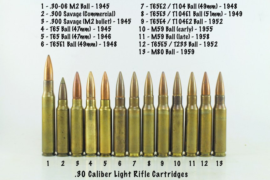
Development of the .30 Light Rifle round, which would eventually become 7.62x51mm, began in 1944, with the round first being referred to as the T65 in 1946. It appears that the rifle is chambered in a version of the T65 cartridge, but which iteration exactly is unknown. However, its chambering does support the theory that the prototype may date from 1947-48. The T65 didn’t take on the now standard 7.62x51mm dimensions until 1949 in the form of the T65E3 round but without a chamber casting it is impossible to know the rifle’s exact chambering.
A photo representing the evolution of the .30 light rifle round (Courtesy of DrakeGmbH)
While Winchester continued to work on adapting the M1 Garand into a select-fire rifle none of their rifles were seriously considered by US Ordnance. At the same time John Garand was working on his own series of select-fire, magazine-fed prototypes (the T20 series) at Springfield while Remington had also been awarded a contract to develop a similar rifle, tested under the designation T22. These projects subsequently gave way to a number of other designs, all chambered in the T65 round, including the T25/47, T44 and T48. These were all tested before the Garand-influenced T44 was eventually selected in 1957, becoming the M14.
Addendum:
Harry Sefried II served in the US Army Air Corps during World War Two before joining Winchester as a firearms designer in 1944. In the 1950s he left Winchester to become Ruger’s chief engineer until he retired in 1979. He died in 2005, aged 84.
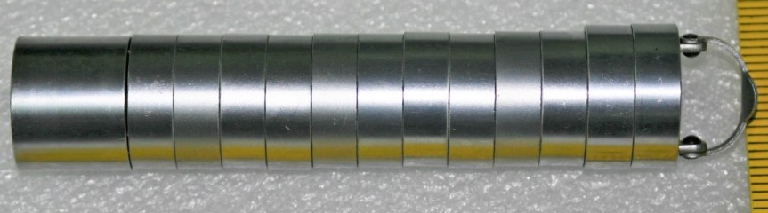
Whilst looking through the piles of surplus ‘kit’ in my friends warehouse in Germany I came across an interesting find, an Explosive Ordnance Disposal (EOD) training kit that has several examples of WWII and after ordnance that might be found on training grounds and former battlefields throughout Europe.
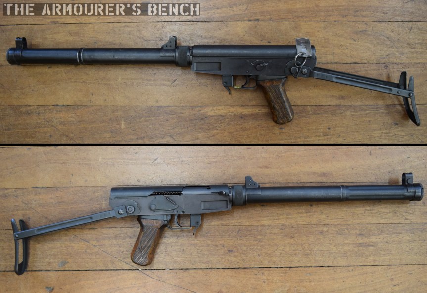
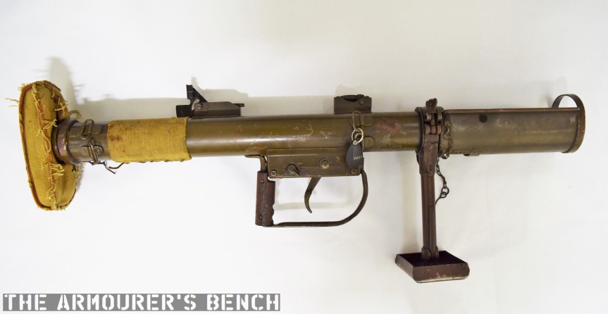
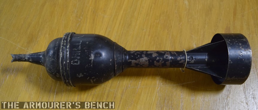
One of the elements from that training kit was a PIAT or Projector, Infantry, Anti-Tank, round. Many of these have been found across northwest Europe since the end of WWII and it was important for EOD teams to be able to identify them and understand how they work in order to safely dispose of them.
A British a PIAT or Projector, Infantry, Anti-Tank (Matthew Moss)
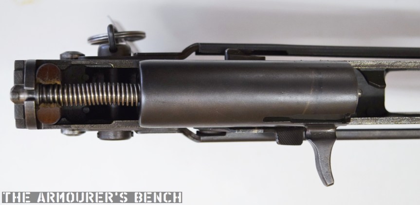
This example is likely an ‘instructional’ round that may have been produced from a previously live round and not subsequently marked as inert. In the video, which was filmed on location from memory, I mentioned that the charge was inside the front cone. Instead the charge was actually just behind the steel cone, which acted as a forcing cone, and has seen been replaced by some sawdust. We can see this in the diagram below, which shows an earlier Mk round but the configuration remains the same:
A close up of the bomb’s markings (Vic Tuff)
This time we examine an example of the Mk3 PIAT Bomb. When I filmed the video I wasn’t sure of the markings but this chart below more clearly explains them:
There were 7 marks of PIAT bomb:
MkI yellow/green/yellow band 808 stamped on green band, red x’s around nose cone
Mk2 as above
Mk3 yellow/blue/yellow band TNT stamped on blue band, red circle around nose cone
Mk4 as above
Inert bomb black with yellow band INERT in white
Drill bomb black with DRILL in white x 2
Practice bomb – to fit the practice insert tray, painted white and it looks nothing at all like a PIAT bomb!
The inert EOD ‘Mk3’ training round (Vic Tuff)
Our inert bomb isn’t painted black, instead it is painted up as a Mk3 to emulate what a live blind found in the field would look like.
An inert ‘Drill’ round painted black (Matthew Moss)
Here’s an extract from the PIAT’s manual explaining how the fuze was fitted to a live round:
From the PIAT manual: The fuze. – Until required for use the fuze is kept in a container attached to the drum tail by a spring clip….
ii. To fuze. – Remove the fuze container from the drum tail and take out the fuze. Remove the thimble from the bomb nose by pressing it downwards and turning it clockwise. Remove the transit plug from the fuze chamber and insert the fuze flat end first. Replace the thimble. The transit plug should be placed in the fuze container and the latter put in the carrier, in case the bomb should later have to be unfuzed.