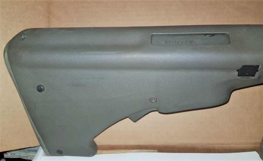
Sometimes all is not as it seems. That was the case when we examined this Steyr AUG. From the barrel and bipod it appeared to be an AUG in an HBAR or Heavy Barrel configuration but on closer inspection we found that it was in fact a rifle receiver, bolt and bolt assembly and chassis that had been paired with an HBAR barrel assembly.
Vic with the Steyr ‘HBAR’ (Vic Tuff)
Ordinarily, the HBAR could be modified to fire from an open, rather than closed, bolt. This example has the standard AUG progressive trigger for semi and full-auto. It does not have the modified bolt carrier, striker or trigger mechanism.
The HBAR has a 4x optic, rather than the rifle’s 1x, while the HBAR-T can be fitted with an optic like a Kahles ZF69 6×42.
A dedicated ‘LMG’ marked AUG stock and bolt carrier (Vic Tuff)
Adoption of the AUG HBAR does not appear to have been widespread and Steyr don’t currently list it as an option amongst their upgraded AUGs. For more Steyr we have previously examined a Steyr AUG SMG conversion and a Steyr MPi 81. We’ll take an in depth look at the AUG and AUG HBAR in the future.
Overall Length: 35.5in (90cm)
Barrel Length: 24.4in (62cm)
Weight: 8.6lb (3.9kg)
Action: Gas operated, rotating bolt – the HBAR typically fires from an open bolt, but this rifle-based example fires from a closed bolt.
Capacity: 30 or 42-round box magazines
Calibre: 5.56×45mm
Destroying railway infrastructure was a key mission for the Resistance groups and SOE agents active in occupied Europe. Numerous methods of damaging or destroying railways were developed, including Exploding Coal, which we have covered earlier in this series. In this 16mm colour footage, believed to have been filmed in 1940, we get an early look at the methods the SOE were developing to destroy track. The ultimate aim was to derail the locomotive and wreck the train with minimal effort and explosive.
In the footage we see two charges have been placed on the piece of track, with detcord attached to both. A soldier, with what appears to be a lever-action Winchester 94, is then seen taking aim. It seems he’s aiming at a striker board attached to ignite the detcord. He fires, we see a puff of smoke and a second later the charges detonate.
The footage then cuts to several men collecting the debris of the shattered piece of track. The track appears to have two large chunks blown out and the top edge, between the two charges, completely blown off.
An early SOE demonstration with the charges set on the rail (IWM)
Later in the war more testing was done and more refined techniques were developed. In their book SOE: The Scientific Secrets Boyce & Everett note that trials of devices and techniques for destroying railway lines carried out at Longmoor where the British Army had extensive sections of track and samples of rails used in different European countries. Trials to find the right quantity and positioning of explosive charges were carried out in late December 1943, these tests would inform later operations.
Fog Signal Igniter (SOE’s Descriptive Catalogue of Special Devices and Supplies)
The SOE’s Descriptive Catalogue of Special Devices and Supplies includes a pair of illustrations demonstrating two methods of laying and detonating these charges. A so-called ‘French’ method with a pair of what the catalogue terms ‘Igniters, Fuze, Fog Signal, MkIA’ ahead of the charges in the direction the train was expected from. The train would crush these Fog Signals firing them and igniting a length of detcord linked to a pair of 3/4lb explosive charges fixed to the track as we see in this film.
Polish Rail Charge layout (SOE’s Descriptive Catalogue of Special Devices and Supplies)
The alternative ‘Polish’ method had the same sized and located explosive charges but placed a Fog Signal either side of the charges to ensure that no matter which direction the train came from the charges would be detonated. This method was used on single track stretches of railway. Both of these methods were rated to ‘remove about one metre of rail.’
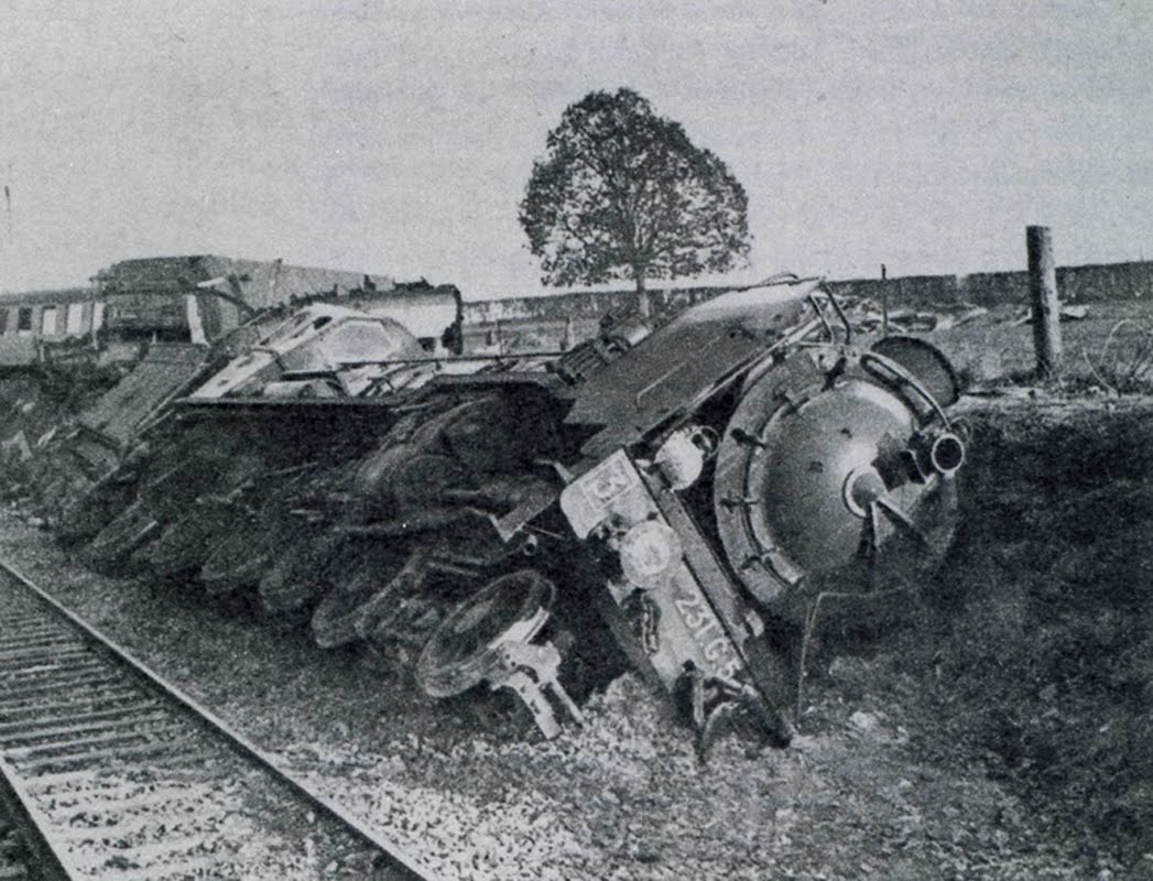
In this photo we see a member of the French Resistance setting an explosive charge on a railway line. While likely a posed photo we do see the pair of Fog Signals which will stet the charge off. These photographs show a pair of trains reportedly derailed by explosive charges.
A derailed French train c.1942 (AIRAN)
Boyce & Everett in their book SOE: The Scientific Secrets suggest that as many as 48,000 ‘Railway charges’, presumable a kit, were produced by the SOE. From the footage we can certainly see this method of destroying rails was effective.
Today, were taking a look at a Winchester prototype developed in the mid-1860s, a period when Winchester was seeking to build on the success of the 1860 Henry Rifle and place the company on a firm financial footing. Oliver Winchester had taken control of the New Haven Arms company before the Civil War and while for a time it had been known as the Henry Repeating Arms Company he eventually sought to put his stamp on the company, renaming it Winchester Arms Company in 1866. At the same time he decided to focus the company’s energies on winning military contracts around the world.
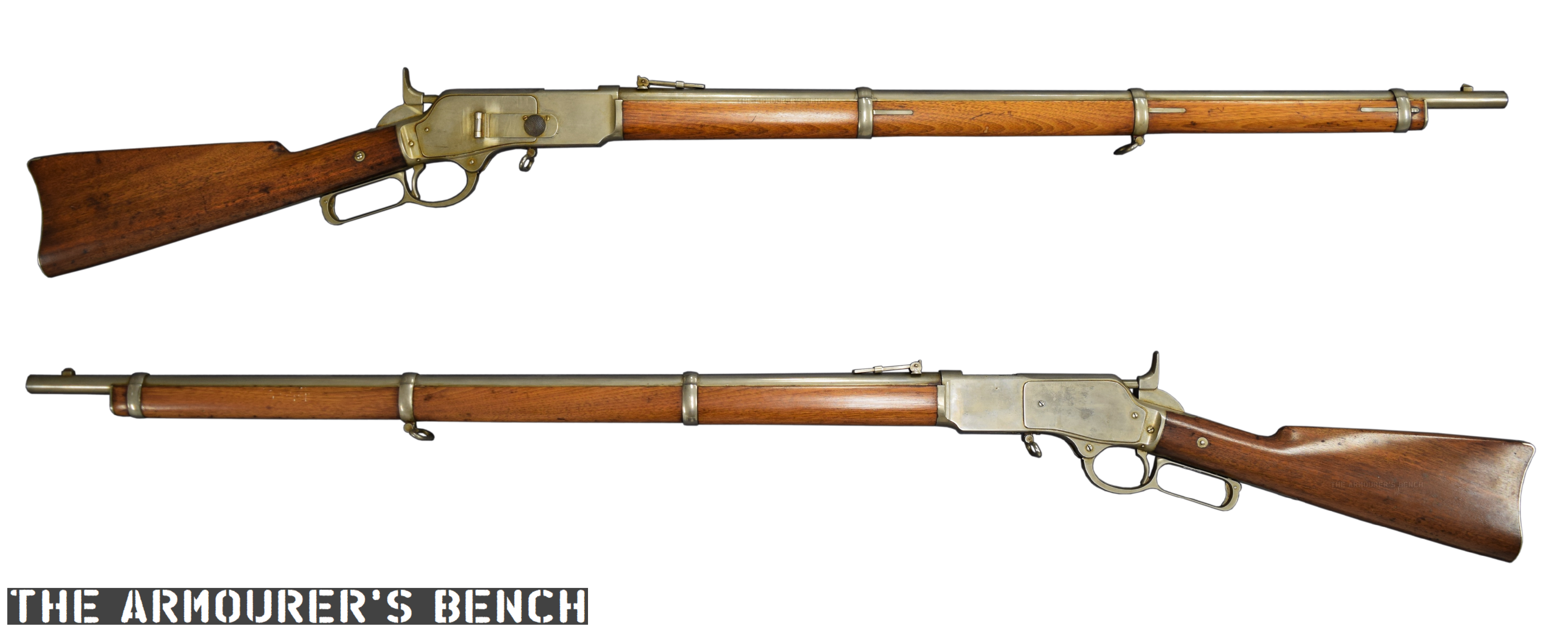
Left & right profiles of King’s prototype musket (Matthew Moss)
This developmental prototype is in the ‘musket’ configuration: with a longer barrel, a bayonet lug and a wooden forend. The prototype represents one of the many developmental steps towards what would become the Model 1866. It has a number of interesting features – a steel, rather than brass, receiver and a hinged loading port developed by Nelson King, Winchester’s superintendent between 1866 and 1875.
The rifle itself was built by Luke Wheelock, Winchester’s model room mechanic and a designer in his own right who would go onto develop his own rifle designs for Winchester.
King’s 1866 patent (US Patent Office)
The rifle is 54.5 inches long, with a 33.75 inch barrel. Believed to have been built in 1866, it is chambered for a .45 calibre rimfire round. King patented his loading port in May 1866. He described how the port worked:
“Through one of the plates S (preferring that one upon the right-hand side) I form an opening, 0, as denoted by broken lines, Fig. 1, and also seen in section, Fig. 7. This opening is formed so as to communicate through the frame directly to the chamber E in the carrier block, as seen in Fig. 3. Through this opening, and while the carrier-block is down and all parts of the arm in a state of rest, insert the cartridges, point first, through the said opening in the plate S into the chamber E the second cartridge pressing the first into the magazine, and so on with each successive cartridge until the magazine is filled, or until the requisite number has been inserted therein, the follower G being pressed up before the entering cartridges. In the rear of the chamber E2 the frame forms a shoulder to prevent the cartridges from being forced out through the opening in the plate S3 is a cover for closing the opening in the plate S3 and is hinged thereto, as seen in Figs. 1 and 7, the hinge being provided with a spring,a1, the tendency of which is to open the cover C. A spring-catch, d, (see Fig. 1,) secures the cover when closed, so that by pressing upon the said catch the cover will fly open. After the requisite number of cartridges have been placed within the magazine, close the cover, as seen in Figs. 1 and 2.”
A close up of the hinged loading gate (Matthew Moss)
To paraphrase: ammunition can be loaded through the opening in one of the receiver side plate when the carrier block is down, insert the cartridges through the opening, pressing the first into the magazine and so on until the magazine is filled… a cover for closing the opening is hinged to the receiver side plate. A spring catch secures the cover when closed.
According to Herbert Houze, King developed the covered loading port design in early January 1866, with a design drawing dating to the 14th January, confirming this.
King altered the design of the rifle’s cartridge carrier so that a cartridge could pass through its lower section straight into the magazine when the action was closed. In theory the aperture could be placed on either side of the receiver, in practice is was placed on the right. Prior to this Winchester had experimented with systems where the tube could slide forward (G.W. Briggs US #58937), a port in the base of the receiver (J.D. Smith US #52934) or a sliding forearm covering a loading port at the rear of the magazine tube (O.F. Winchester UK #3284 [19/12/1865]).
A look inside the hinged loading gate (Matthew Moss)
King’s system had the benefit of allowing the rifle to be quickly loaded or topped off without rendering the rifle unusable while loading. Positioning the port in the receiver allowed the magazine tube to be enclosed by a wooden forend.
A cartridge guide was fitted inside the receiver which guided rounds through the cartridge carrier and into the tube magazine. The rounds were prevented from popping out of the magazine, when the carrier was aligned and the cover open, by a shallow shoulder which projected in line with the carrier’s channel to hold cartridges in the tube by their rim.
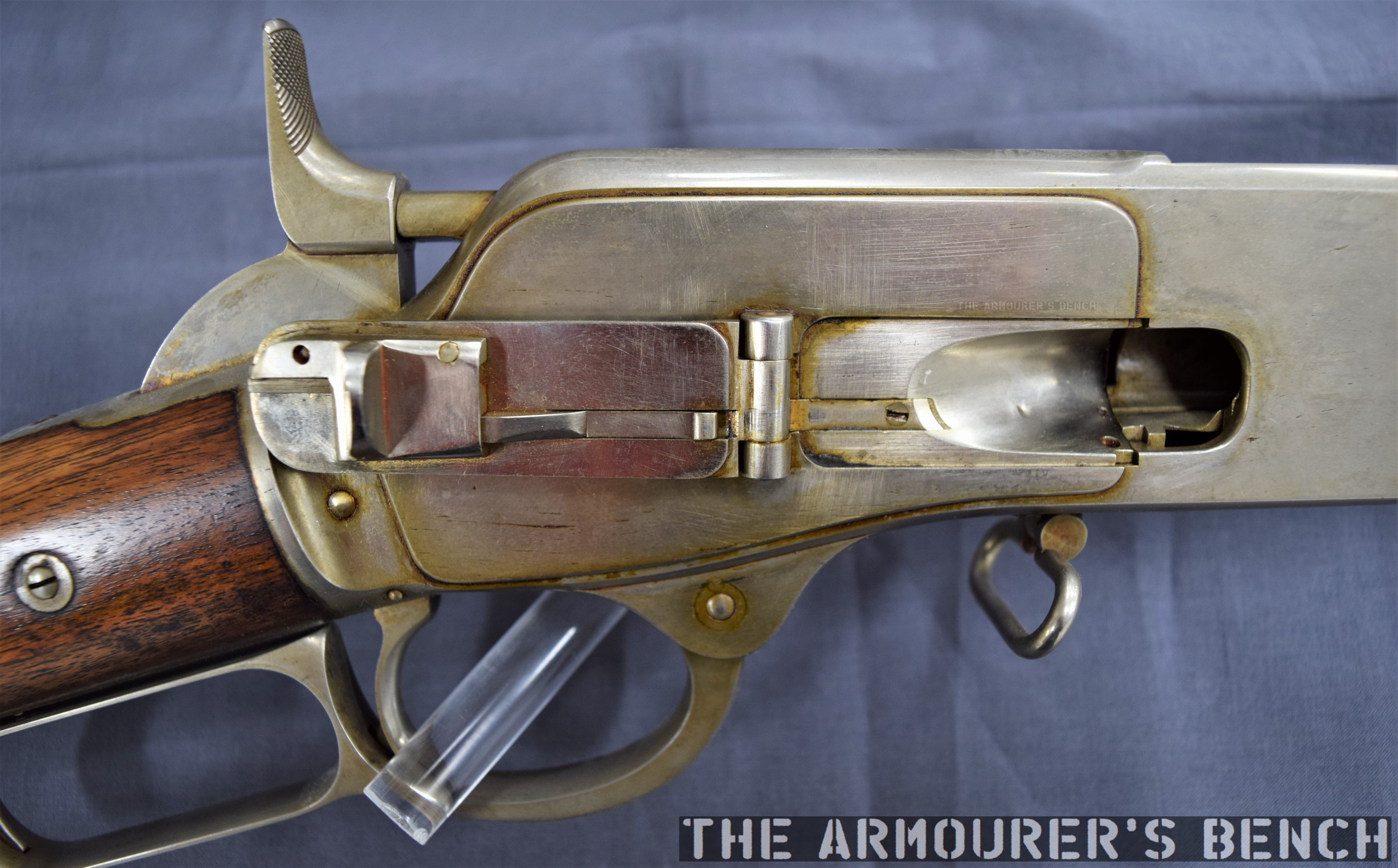
The musket with its action open, bolt to the rear and loading gate open (Matthew Moss)
The hinged cover is held shut by a spring catch mounted on the rear of the cover. When the knurled section on its front is pressed rearwards the cover pops open. The spring catch is actuated when it tensions against the cover’s hinge as it is closed. On the back of the cover there is also a cartridge stop for when the cover is closed.
Another small but interesting feature of the prototype is the catch at the rear of the lever loop, this differs from the manually turned catch seen on the Henry and production 1866. This design appears to be a much better safety feature, simply requiring the user’s hand to depress the catch to unlock it from the stock. It also appears to be a much simpler mechanism than that seen in later models like the Model 1895. The trigger also had an extension protruding from its rear which appears to prevent the trigger from being pulled when the lever isn’t full closed. Neither of these features appear in King’s May 1866 patent.
It appears that the idea of the port with a hinged cover was superseded by what we now recognise as the classic Winchester loading gate in the summer of 1866. King’s new system replaced the hinged cover with a piece of stamped spring steel attached to the inside of the receiver side plate by a screw. The spring steel gate could be pushed in, with the nose of a cartridge, to allow rapid loading. The front face of the gate formed a cartridge guide removing the need for the separate machined guide used in King’s earlier iteration of the system.
(Rock Island Auction Company)
King’s revised loading port system required just five, rather than twelve, components: King’s altered cartridge carrier, receiver side plate, spring metal loading gate plate and retaining screws. This simple but elegant design continued to be used for decades on various models of rifle. The company were so pleased with the refinement of the rifle that, according to R.L. Wilson, King was awarded a payment of a $5,000 reward by the company’s board of directors.
Winchester introduced the rifle in 1866, with the first deliveries being made early in 1867, the new rifle was offered in various barrel lengths and patterns including carbine, rifle and ‘musket’. Winchester found some success selling 1866 rifles to the militaries of France and the Ottoman Empire, while many other countries purchased rifles for testing including Britain and Switzerland (whom came close to adopting the Winchester.) The rifles also found success on the civilian market with around 4,500 sold in the first five months.
Right side profile of the rifle showing the hinged loading gate (Matthew Moss)
The Scientific American described the new rifles as “elegant in appearance, compact, strong, and of excellent workmanship. On examination we find its working parts very simple, and not apparently liable to derangement.”
King incrementally developed his loading system before radically simplifying it and this prototype rifle represents an important developmental step in the design of what would become the Model 1866 – one of Winchester’s most important rifles.
Special thanks to the Cody Firearms Museum for allowing us to take a look at this fascinating prototype rifle.
If you enjoyed this article and video please consider supporting our work here. We have some great perks available for Patreon Supporters. You can also support usvia one-time donations here.
Bibliography:
Winchester Repeating Arms Company, H. Houze (1994)
Winchester: An American Legend, R. L. Wilson (1991)
During the Second World War Britain’s Special Operations Executive (SOE) developed a whole series of sabotage devices for use behind enemy lines. Using unique archival footage this series of short videos examines some of the weapons developed for use by SOE agents in occupied Europe. In this episode we look at an explosive magnet bomb, designed to be attached to any magnetic surface and detonate to destroy machinery or vehicles. It later evolved into the small pocket-sized ‘Clam mine’.
Today, we’re lucky enough to have some colour footage showing the of testing of a magnetic bomb which could be attached to the petrol tank of vehicles. The footage comes courtesy of the Imperial War Museum.
A still from the footage showing the charge placed on the body of the car (Imperial War Museum)
From the film we can see that the bomb consisted of a small block of plastic explosive, a pair of strip magnets (or possible a horseshoe-shaped magnet) and a Switch No.10 time pencil delay detonator. The explosive block itself looks to be slightly smaller than the SOE’s standard 1.5lb charge.
In the film we see the bomb placed on the boot (or trunk) of a saloon car before various civilians and a corporal experiment with various ways of covertly attaching the bomb to the underside of the car. At one point the corporal allows himself to be dragged along behind the vehicle before making his escape.
Luckily the 16mm footage, filmed by Major Cecil Clarke, also shows us the effect of the explosive charge mounted on a petrol tank full of fuel. According to the details listed for the film by the Imperial War Museum the footage was filmed in 1940, at SOE Station XVII, located at Brickendonbury House in Hertfordshire.
A still from the footage showing the bomb’s magnets (Imperial War Museum)
This configuration of the bomb doesn’t appear in the Special Operations Executive’s Descriptive Catalogue of Special Devices and Supplies published in 1944. However, Colonel Leslie Wood, Station XII’s commanding officer, described the demonstration put on during a visit by Brigadier Robert Laycock of the Commandos and William Donovan, the head of the American OSS in June 1942. One of the scheduled demonstrations was the “Effect of small ‘magnet’ charge of explosive on petrol tank of car.”
It appears that this ad hoc magnet charge evolved into ‘the Clam’, which was a smaller, version of the magnetic Limpet mine. The Clam evolved through a number of marks with the MkI having a stamped sheet metal casing and the later MkIII using a bakelite, plastic casing. Both were made up of a plastic explosive charge inside a rectangular, rounded case with a pair of magnets at either end. They were detonated by either a Time Pencil or an L Delay fuse attached to a No.27 detonator. The MkIII had 8oz (226g) of high explosive filler, such as TNT/Tetryl 55/45.
MkIII Clam (Imperial War Museum)
While unlike the larger Limpet they weren’t developed for under water use but the Clam could be mount onto any vaguely flat magnetic surface including engine blocks, fuel tanks, crank cases, cylinder blocks, rail tracks and steel plate.
At just 5.75” x 2.75” x 1.5” they were easily concealable, could be carried in a pocket and were non-descript enough not to draw attention. An estimated 68,000 Clams were made under supervision at Aston House according to Des Turner’s book on Station XII.
We’re lucky enough to have some unique colour footage showing the of testing of some of these explosive devices and in this article we will examine an incendiary-filed case.
In this piece of 16mm colour footage, filmed in 1940 by Captain Cecil V. Clarke, we see what appears to be an attaché case containing three medium-sized bottles, which likely contains a mix of petrol and paraffin or some white phosphorus, prepared for testing at the bomb range at Brickendonbury in Hertfordshire, a Special Operations Executive training and research centre codenamed Station XVII. It’s believed that these films may have been produced as teaching aids for the agents trained at Station XVII and this film may have been shown during a lecture.
A still from the footage showing the case being set up at the test range (IWM)
While incendiary briefcases, attaché cases and even suitcases are listed in the 1944 SOE Descriptive Catalogue of Special Devices and Supplies they were quite different from this case. They were primarily designed for the quick destruction of documents and items carried inside them. They used sheets of potassium nitrate to burn the case’s contents.
The incendiary case seen in this footage on the other hand appears to be designed to be clandestinely placed and detonated with a delay fuse, to set nearby flammable objects on fire. What was described as a ‘Delayed Action Incendiary’.
The Incendiary Suitcase entry from the SOE’s Descriptive Catalogue of Special Devices and Supplies
In this footage of another separate test we get an idea of the destructive capability of just one of the bottles.
It’s possible that this incendiary case was a proof of concept test for the later cases or perhaps a demonstration of a concealed incendiary device Station XVII were working on. SOE developed a large number of bespoke explosive devices for various missions, so while this device may not have become ‘standard issue’, it may have been developed for a specific purpose.
The US entered the Great War with no tanks of their own – by the end of the war they had designed and built their first tank, collaborated on a leviathan heavy tank with Britain and built their own copy of the French FT. In this video we look at how the US Army hit the ground running and formed two tank corps and built their first tanks.
In recent videos we’ve looked at all of the US Army’s early tanks, here’s a round up:
The tinny 3-ton Ford was the first American designed and built tank. Aiming to use readily available parts and materials it took inspiration from the French Renault FT but was smaller and lacked the FT’s revolutionary turret. The Ford was only lightly armoured and did have the best cross country handling. Check out our full article on the Ford here.
The MkVIII was a truly ‘international’ effort with the US, UK and France all working on the project. The US and UK provided the mechanical components while France provided a factory to assemble the formidable vehicles. The MkVIII wasn’t ready in time to see action during the war but remained in US service into the 1930s. Check out our full article on the MkVIII here.
The US also sought to produce their own licensed version of the French Renault FT, making some slight changes the tank was adopted as the M1917 but despite production being well underway by late 1918, none of the M1917s reached the front. Instead they became the backbone of the US Army’s interwar tank force. One even climbed a mountain!Check out our full article on the M1917 here.
In 1940, following the evacuation from Dunkirk the British Army was in desperate need of small arms, with over 100,000 rifles left behind in France. In dire need of rifles Britain turned to the US and its huge industrial base and approached a number of companies about tooling up to produce Lee-Enfield Rifle No.4s. Savage Arms took on one contract and projected production of 1,000 per day but establishing production of a rifle US companies didn’t have the tooling and gauges for would take time.
Right side of the Remington (Matthew Moss)
Remington was also approached by the British Purchasing Commission and asked if they could manufacture up to 400,000 rifles. Remington estimated it would take up to 30 months to tool up for No.4 production. However, Remington believed that if they could lease the old tooling previously used at the Rock Island Arsenal to produce M1903s, from the US Government, they could tool up to produce the M1903 in just 12 months. It was suggested that the tooling be adapted to produce rifles chambered in the British .303 cartridge. Some ergonomic changes could also be made so the rifles mimicked the British No.4.
Left side of the Remington (Matthew Moss)
On 12th December 1940, the British government issued a Letter of Intent to Remington for the manufacture of 500,000 rifles in .303 British. Some sources suggest the British agreed to an advanced payment of $4,000,000. Much of this covered the lease, transport and refurbishment of the M1903 tooling. The rest went on the purchase of raw materials and the necessary accessories for half a million rifles.
The tooling lease was agreed in March 1941, and the US Government also supplied 600,000 stock blanks which had been in storage in exchange for ammunition produced by Remington. With the passage of the Lend-Lease act, on 11th March, the Remington contract came under the control of the US Government, rather than a private order. Remington received the last tooling shipments from Rock Island Arsenal on 22nd April, and by the end of May had the production line up and running.
A detail view of the rifle’s action and follower note the ‘2’ stamped on the follower (Matthew Moss)
A contract to produce the hybrid rifles at a cost of $5 per rifle was agreed in late June. Remington’s engineers began setting up the equipment and working out an ad hoc production layout that would allow 1,000+ rifles per day to be built. At least four pilot models were built, with some of these guns being sent to Britain. The rifles were reportedly received in September 1941, and following preliminary examination were described as “very successful”. Four of the rifles were distributed for further testing but by the end of 1941 the project had been abandoned.
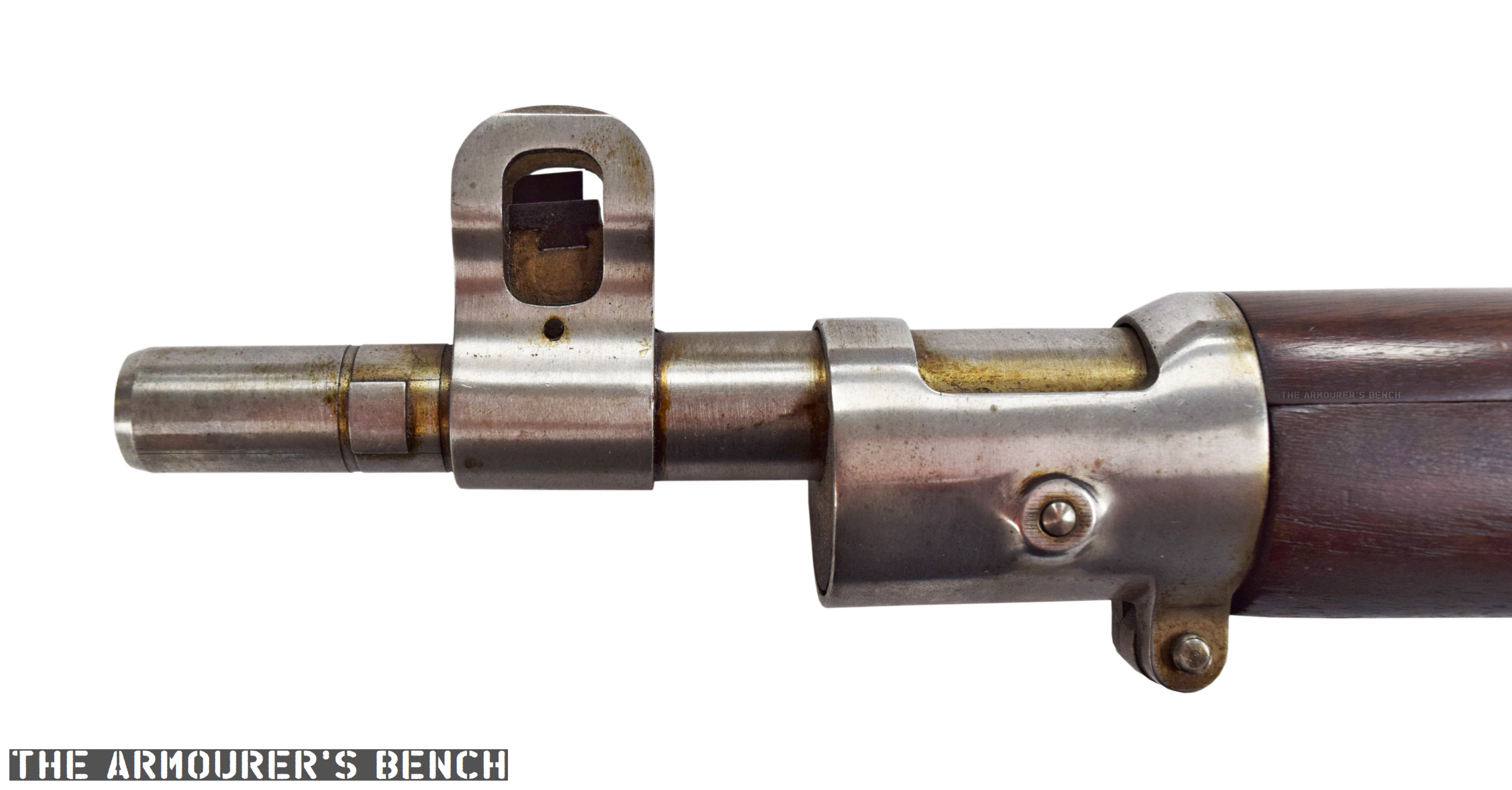
A close up of the adapted muzzle and foresight so the rifle could fit a No.4 bayonet (Matthew Moss)
Remington made a number of external and internal changes to approximate the British No.4. They fitted a front sight post with sight protectors which was moved further back from the muzzle to enable the rifle to mount a Rifle No.4 spike bayonet. As such the upper barrel band does not have a bayonet lug.
Many of these parts are still in-the-white, unfinished, including the barrel, barrel bands, floor plate, front sight assembly, rear sight assembly and the bolt itself. The bolt does, however, have a parkerized cocking piece.
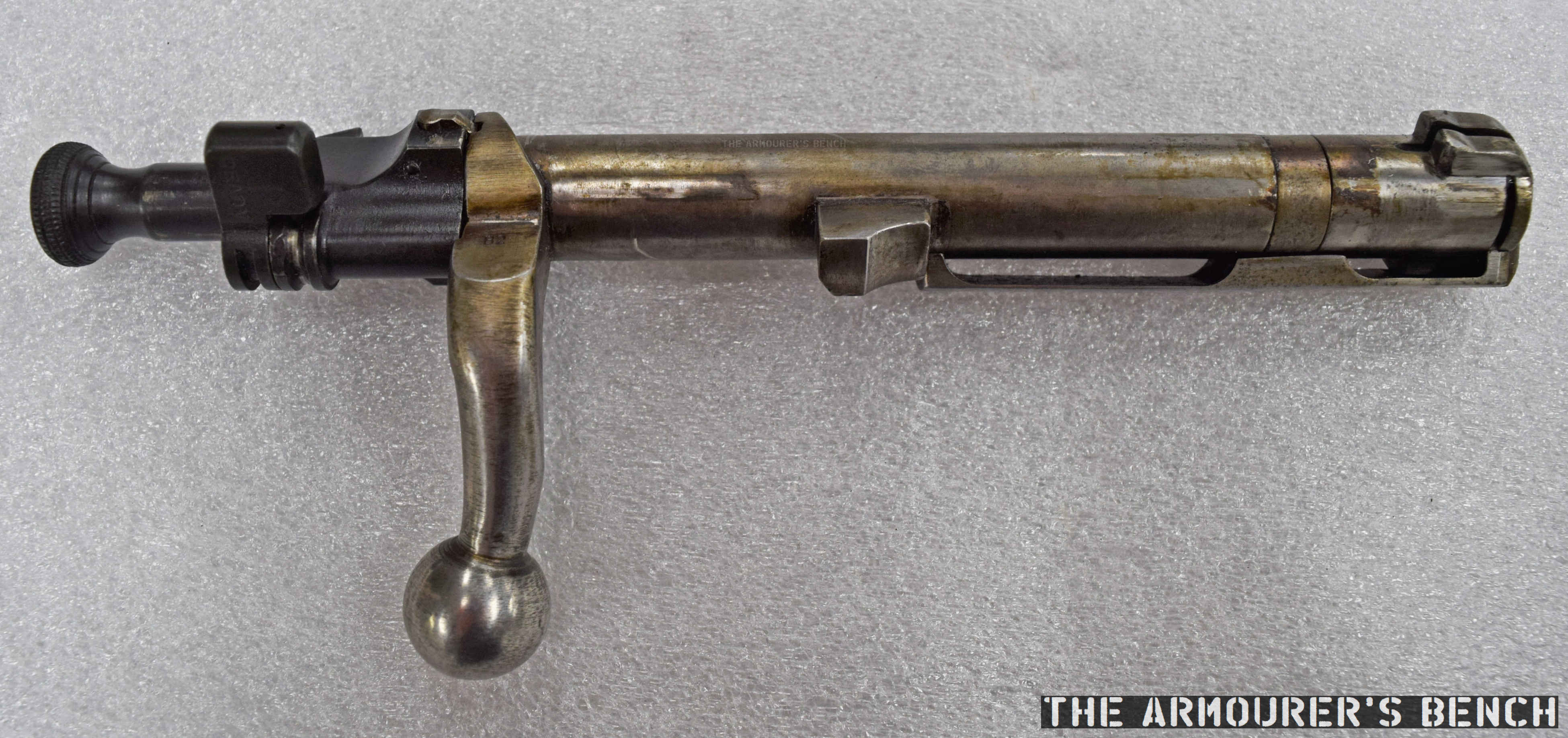
The rifle’s bolt (Matthew Moss)
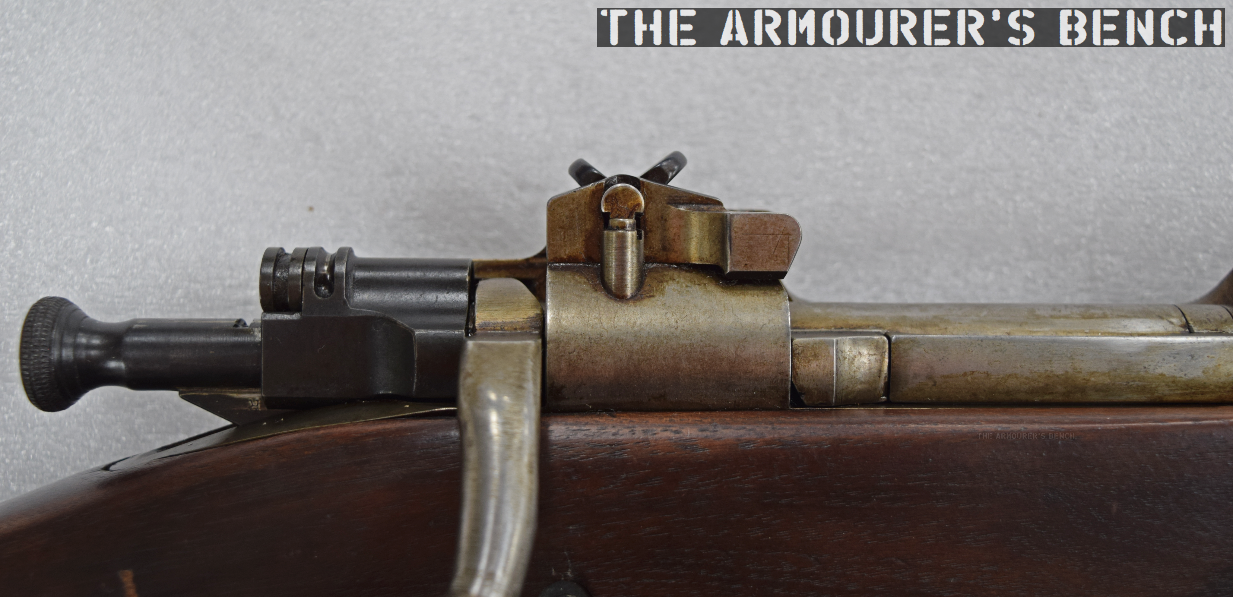
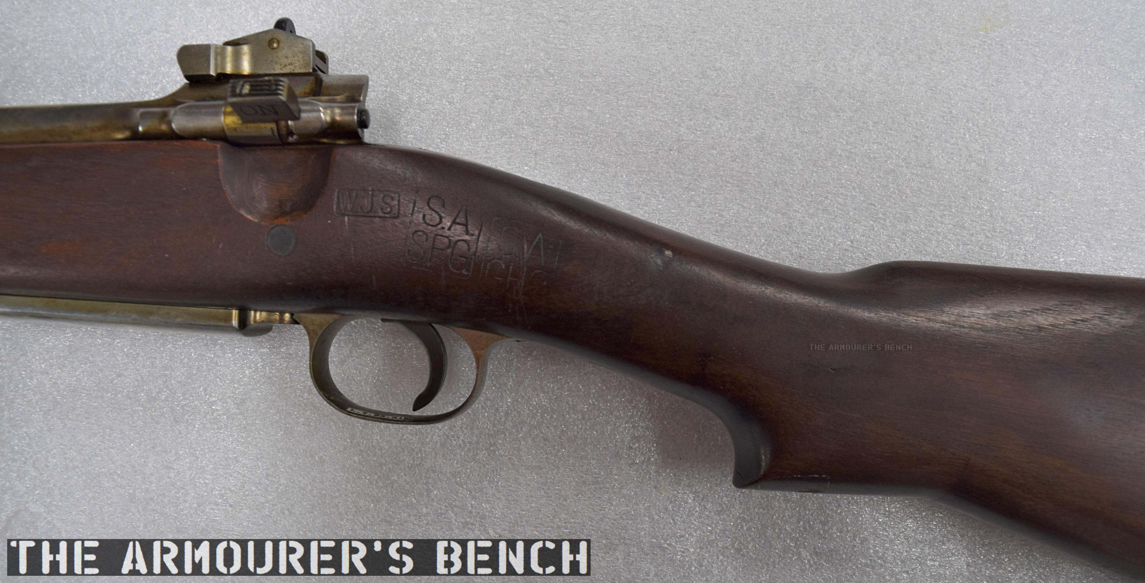
The hybrid also moves the rear sight back onto the receiver, which necessitates a longer piece of wooden furniture covering where the M1903’s ladder sight would normally be. The style of rear sight was also changed to a two-position flip sight with apertures for 300 and 600 yards mimicking those seen on the No.4 Mk2.
A close up of the rifle’s bolt, cocking piece (which wasn’t properly inserted) and rear sight (Matthew Moss)
They also redesigned the charger guide to support the Lee-Enfield-type chargers rather than the M1903 stripper clips. The bolt was adapted to work with Britain’s rimmed .303 round, with the extractor modified for the British cartridges wider, thicker rim.
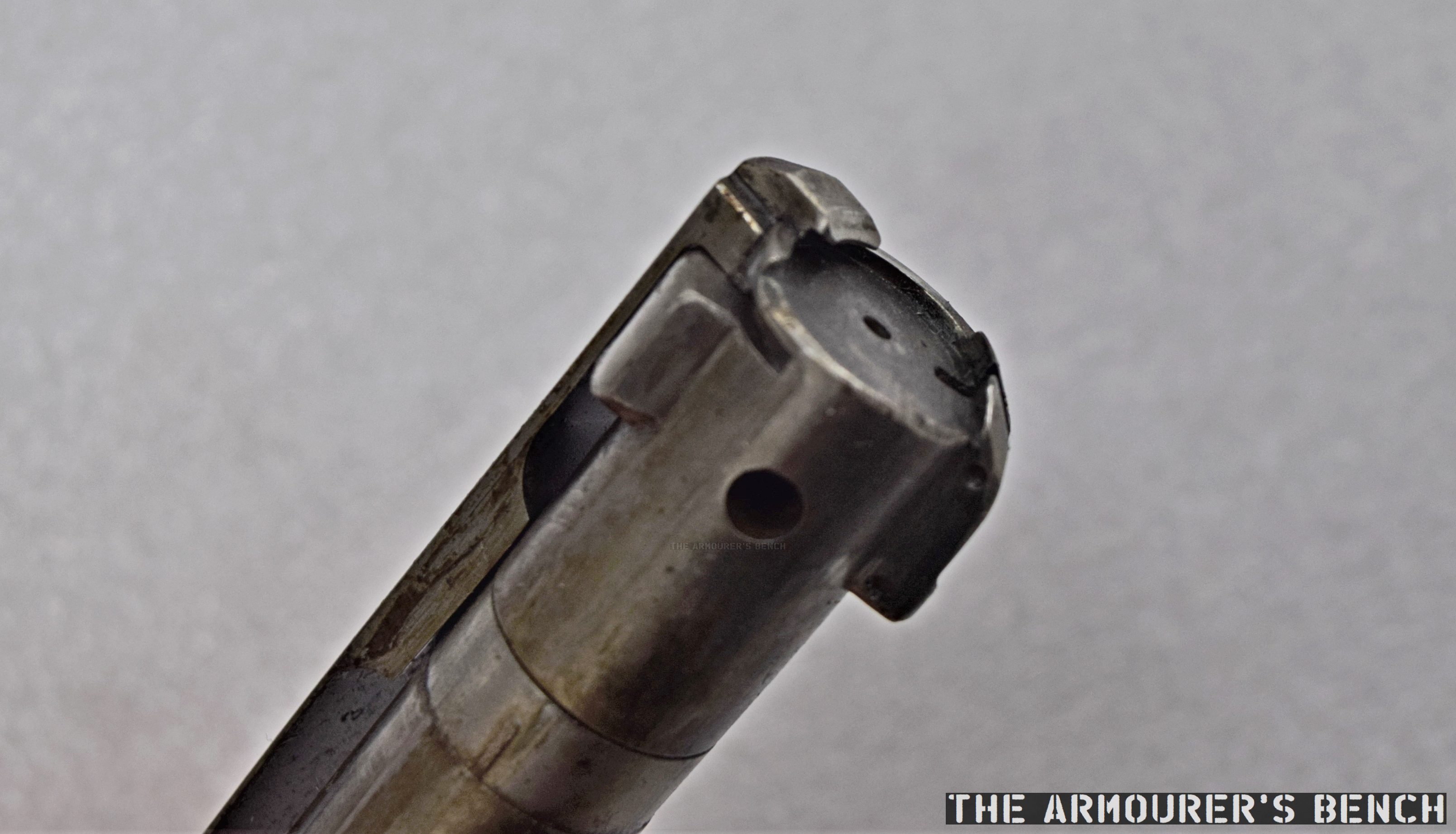
A close up of the bolt head (Matthew Moss)
The rifle did not have the Lee-Enfield’s detatchable box-magazine, instead retaining the M1903’s 5-round internal magazine. The magazine follower does not appear to have been altered either. Markings on the rifle are minimal and include a ‘7’ on the front sight post, a ‘B2’ on the bolt handle and a ‘2’ stamped on the magazine follower. No roll marks or serial numbers appear to be present.
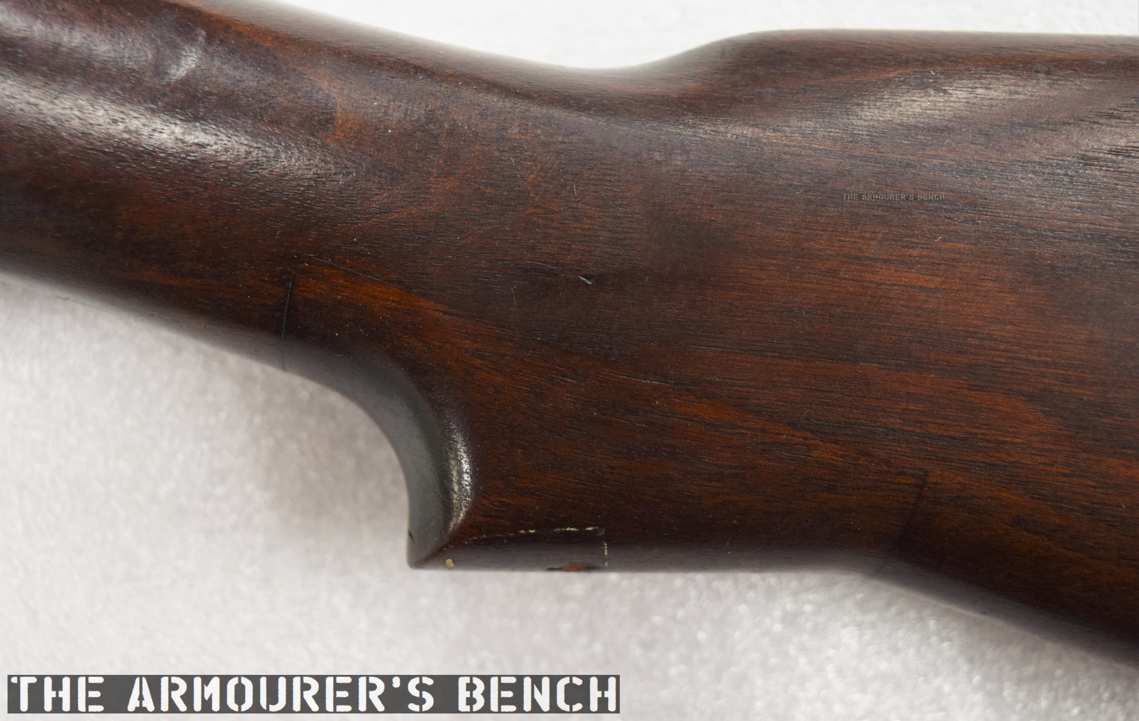
The faux Lee-Enfield stock with spliced in semi-pistol grip (Matthew Moss)
The rifle’s stock has also been adapted, so instead of a straight wristed-stock a piece of wood has been spliced in to create a Lee-Enfield style contour, forming a semi-pistol grip. The stock is marked with the inspector marks ‘WJS’, which indicate the stock was originally inspected by W.J. Strong and accepted between 1918 and 1921, as well as a pair of later Springfield Armory inspection cartouches: ‘SPG’ – the initials of Stanley P. Gibbs, who was an inspector at Springfield Armory between 1936-1942 and ‘GHS’ – the initials of Brigadier General Gilbert H. Stewart (GHS), Springfield’s commander in the late 1930s- early 1940s. This would suggest that the stock was refurbished at Springfield Armory before being transferred to Remington where it was subsequently adapted.
A detail shot of the stock’s Ordnance stampings (Matthew Moss)
In August 1941, the US began its re-armament programme and in September the British contract with Remington was cancelled. At the same time production in Canada and at Savage’s J. Stevens Arms division in the US had gotten underway and it was decided that the adapted hybrid .303 M1903s developed at Remington was no longer needed. The hybrid contract was formally cancelled in December 1941, and additional .30-06 M1903s and M1917s were taken under the Lend-Lease Agreement to fulfil the needs of the Home Guard. Savage believed that they could significantly increase the number of rifles they could build per day, they managed to enter full production by the end of 1941 and by 1944 had produced well over 1 million No.4s.
Remington went on to produce M1903s for the US military, overcoming issues with the original engineering drawings and the tooling dimensions to eventual produce 365,000 M1903s by mid-1943, before switching to production of the M1903A3 pattern and producing 707,629 rifles. In total Remington produced 1,084,079 M1903-pattern rifles during World War Two.
The Remington .303 M1903 hybrids are perhaps the rarest M1903 variant, with only a handful built. They would likely have been perfectly serviceable rifles and helped plug the desperate gap in Britain’s arsenal. Rapidly moving events ensured that these rifles became a footnote in both the Lee-Enfield and Springfield 1903’s histories.
Special thanks to both Remington and the Cody Firearms Museum for allowing us to take a look at this extremely rare rifle.
‘Production of Military Rifles by Remington Arms Company in Ilion, New York During World War II’, American Society of Arms Collectors Bulletin 92:14-24, R. Marcot
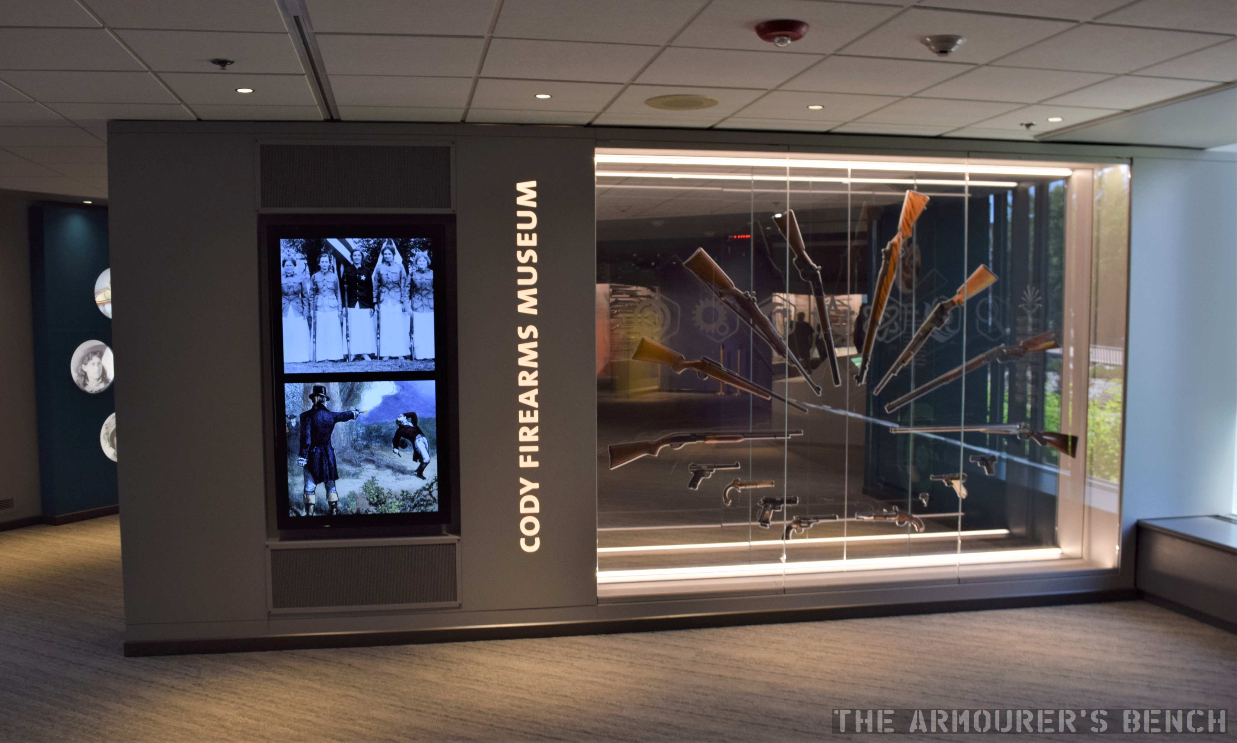
Last summer I had the chance to visit the newly renovated Cody Firearms Museum. With the ongoing Coronavirus Pandemic I thought now was a good time to finish my walk-around video taking a look at the new museum.
The museum has always had an extremely impressive collection of firearms and gun related artefacts, some of which we’ve been lucky enough to feature in videos, but the new museum puts more of these amazing firearms on display than ever before.
The CFM’s new and improved ‘gun fan’ (Matthew Moss)
The $12 million renovation has also allowed the museum to become much more interactive too with working models, touch screens and shooting simulators.
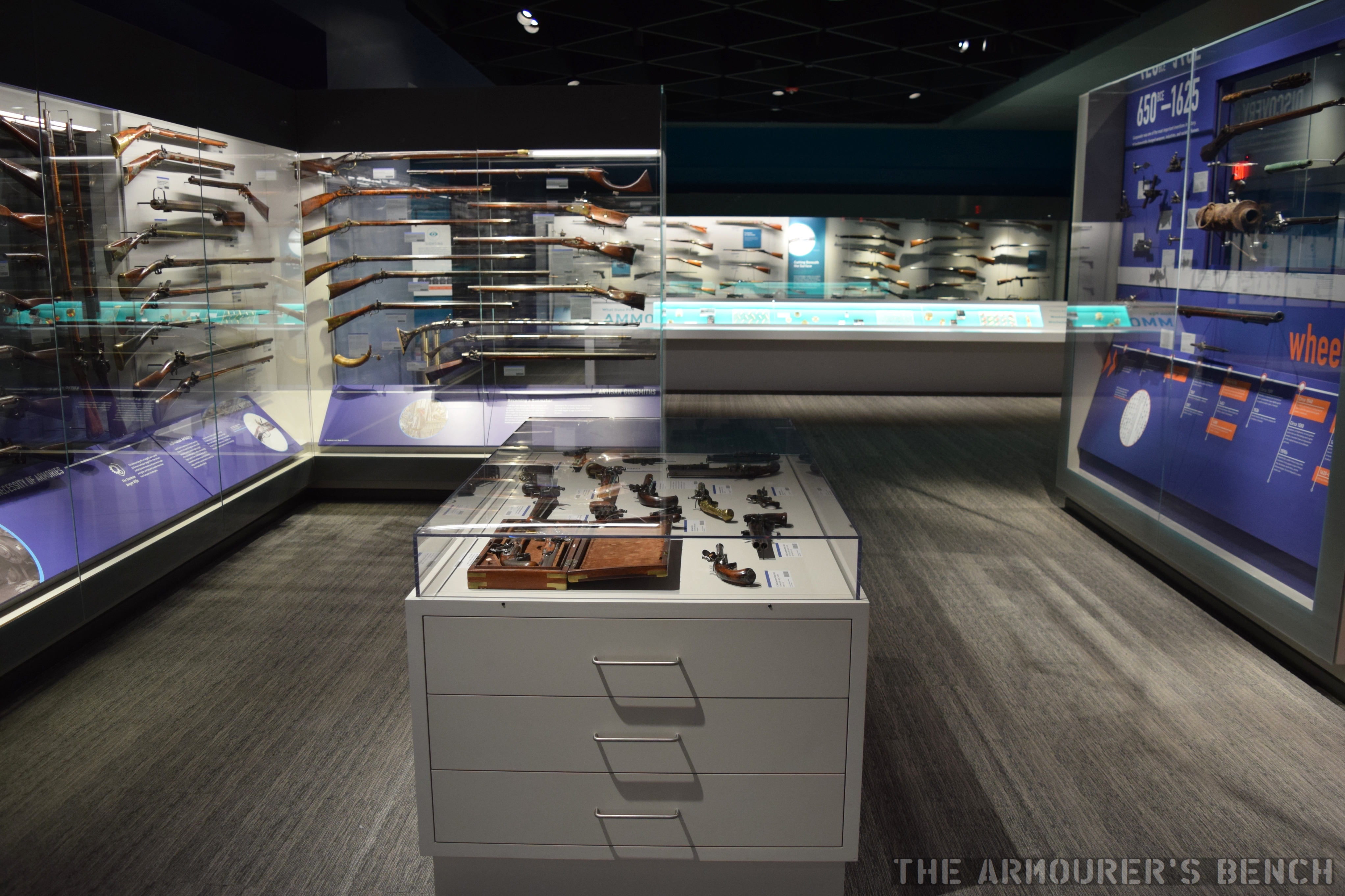
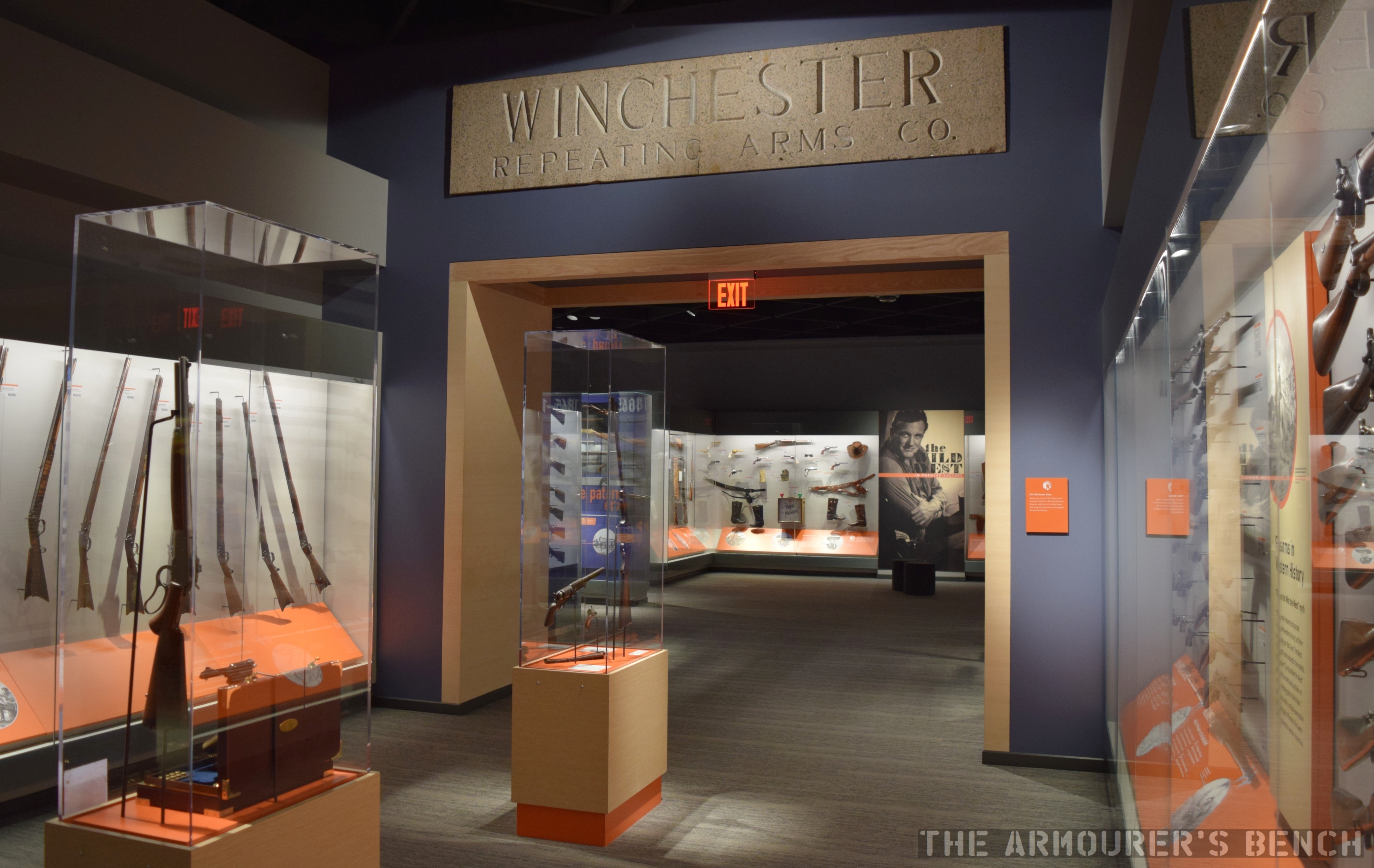
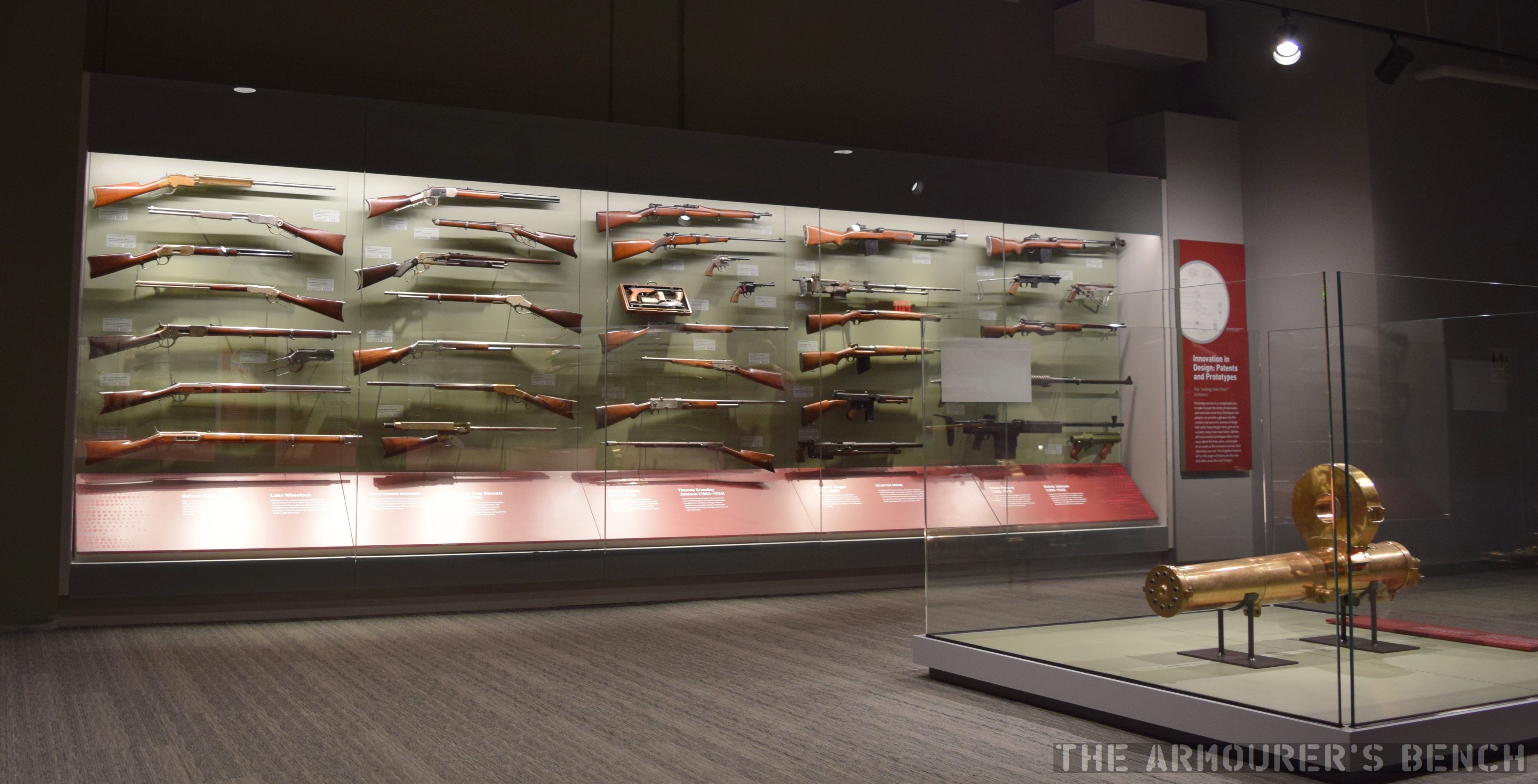
A view back through the first main gallery (Matthew Moss)
A new intuitive layout lets you explore firearm history either by chronology or by theme. In the photo above we can see some of the displays in the chronological gallery that shows the evolution of civilian and military firearms from their invention to the present.
Some of the weapons of the West on display along with the original Winchester factory name stone (Matthew Moss)
One of the features I really liked was that many of the cases can be viewed on both sides allowing you to see all around the firearms.
Around the exhibits are touch screens where you can call up more information, first hand war stories and even animations of how various firearms work.
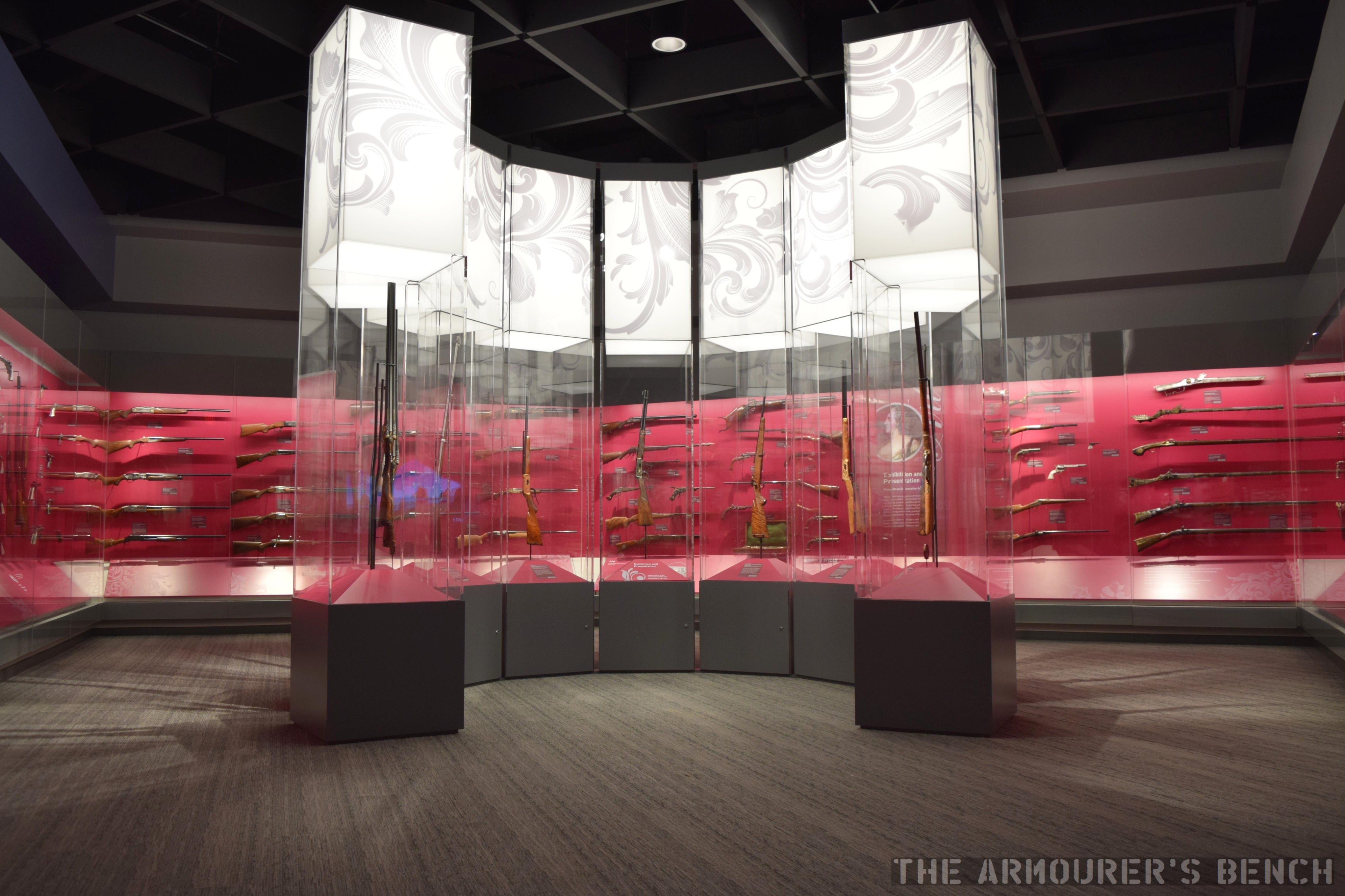
A gallery full of beautifully engraved firearms including some presidential presentation pistols (Matthew Moss)
There is also a gallery of ornately decorated firearms which includes some incredible pieces.
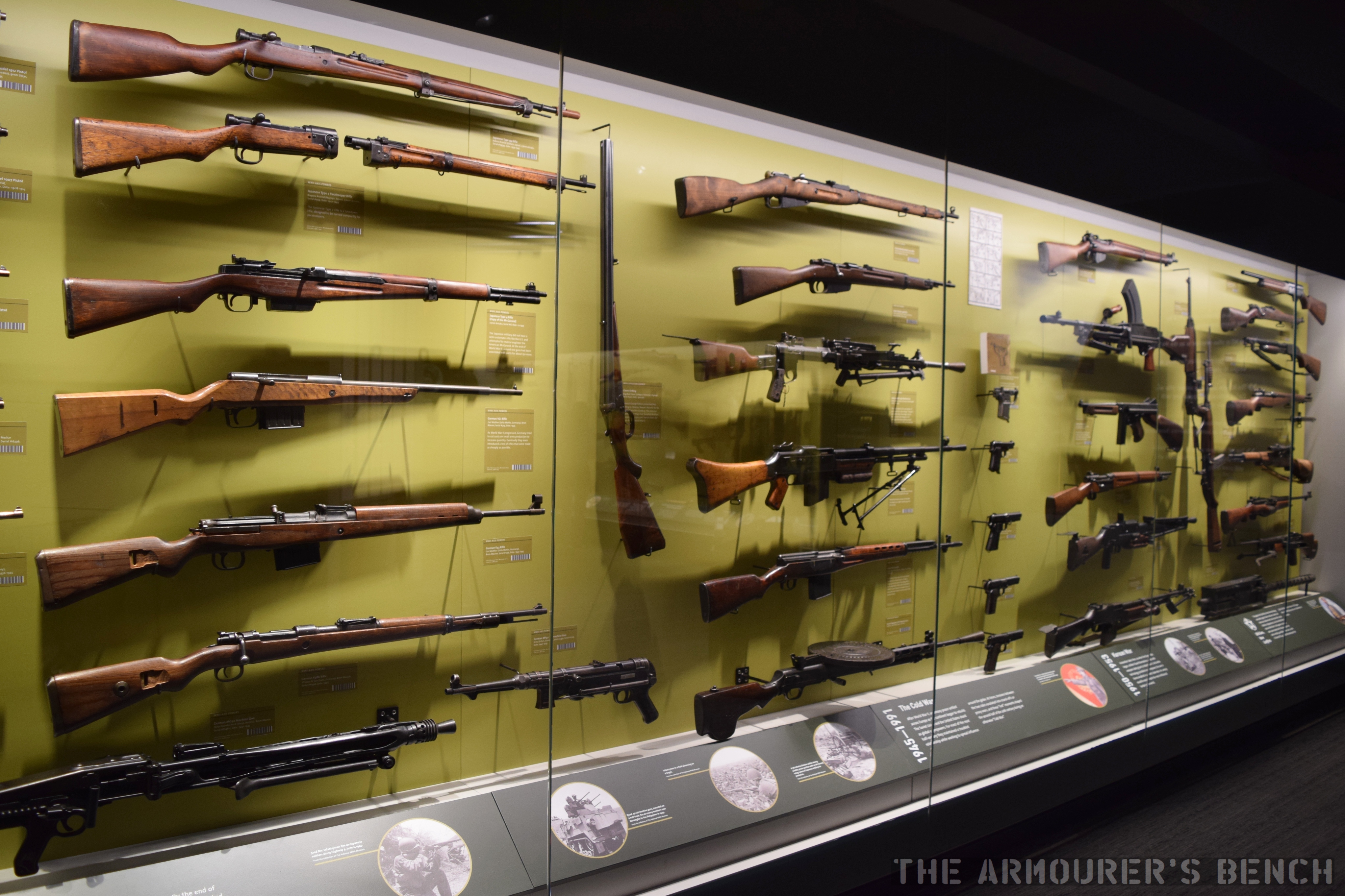
A detail shot from the military gallery (Matthew Moss)
Unsurprisingly, the military gallery was one of my favourite parts of the museum with dozens of guns organised by conflict and period.
One of the cases in the military gallery (Matthew Moss)
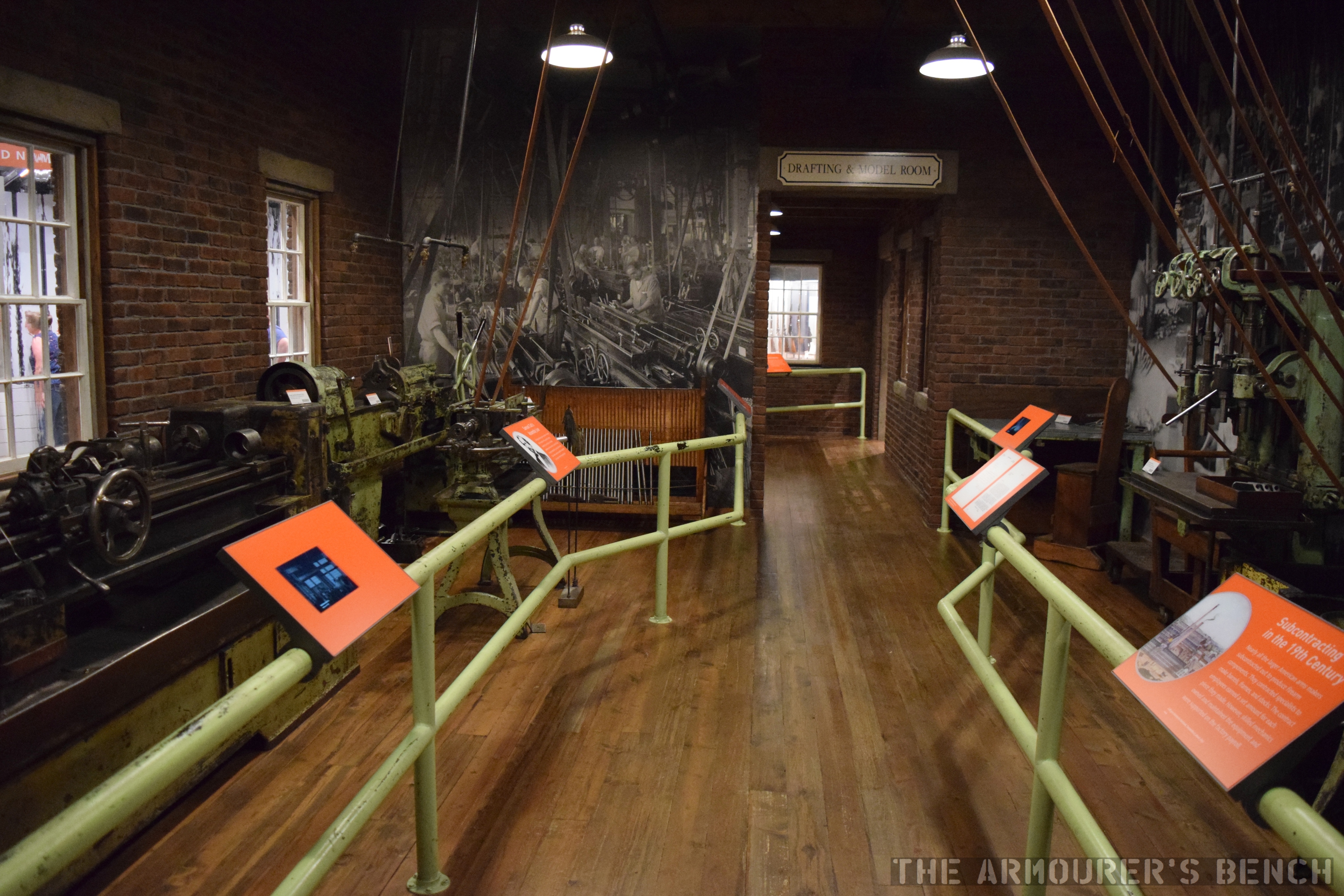
A look back through the recreated machine shop (Matthew Moss)
One of the best features of the original museum has also been retained, a recreation of a gun factory’s drafting room and machine shop.
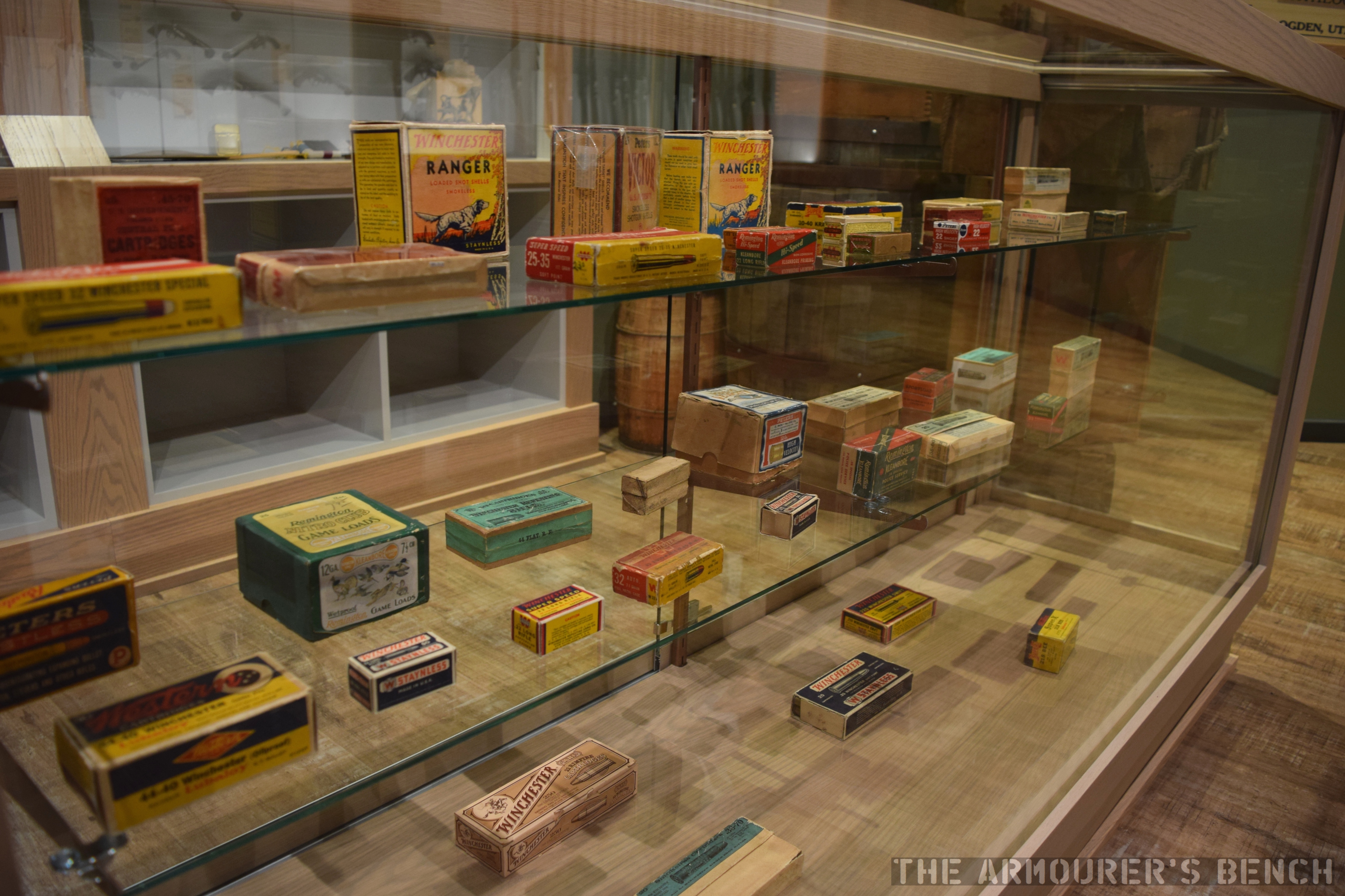
A detail shot of some of the ammunition packaging on display in the ‘general store’ (Matthew Moss)
One of the most interesting little sections is a recreation of a general store showing off some of the items that companies like Winchester made alongside their well known firearms.
A case dedicated to experimental prototypes with the Gatling used in the initial development of the Vulcan in the foreground (Matthew Moss)
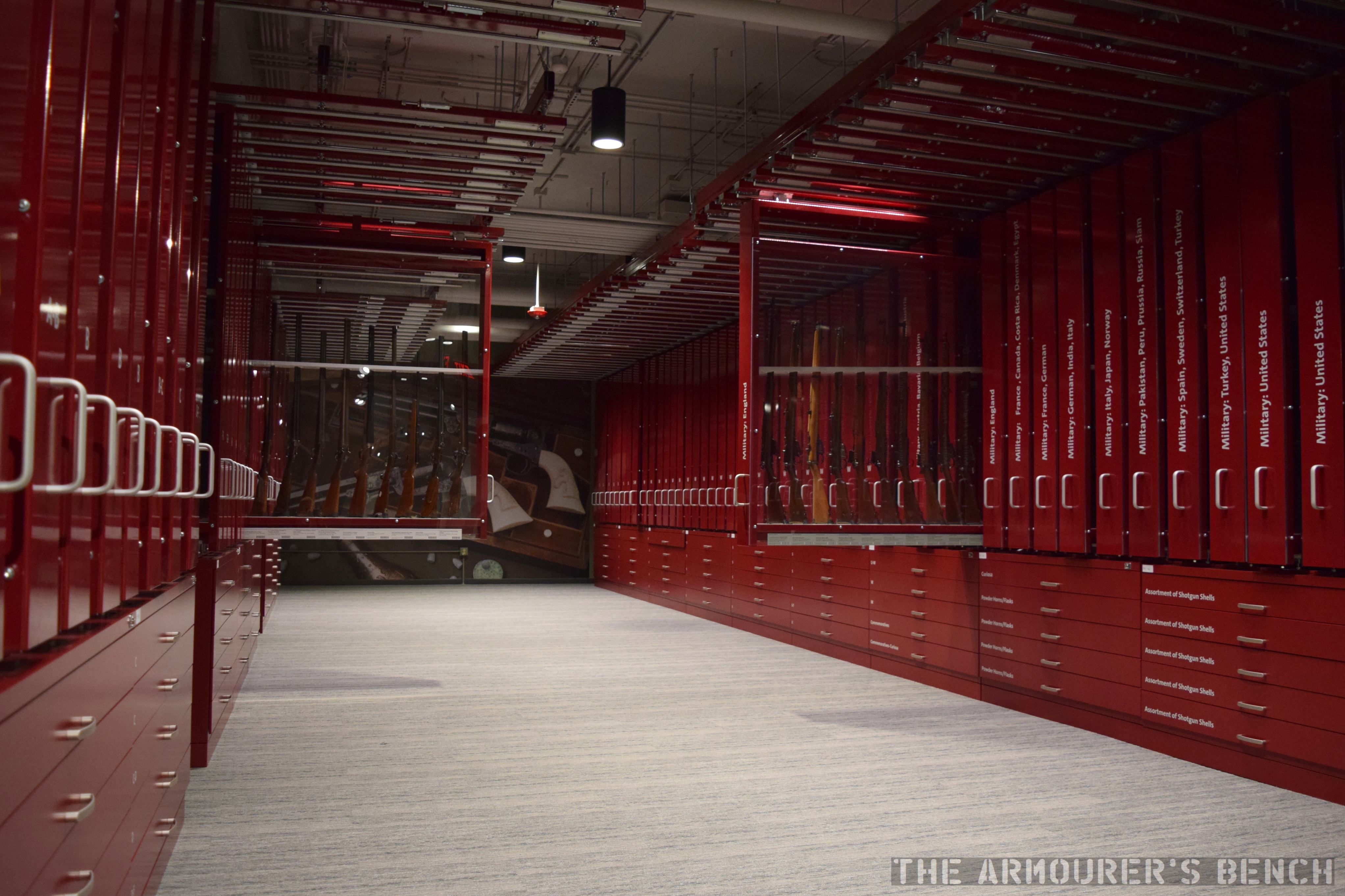
Downstairs is a space dedicated to experimental prototypes and a rolling wall of cases that include examples of hundreds of types of firearms and ammunition.
Some of the rolling cases open in the hall dedicated to showing off as many firearms as possible (Matthew Moss)
The newly refurbished museum puts the collection front and centre in a way that will enthral the average museum-goer and satisfy any avid gun enthusiast.
You can find out more about the museum here and check out some of the firearms we have had the privilege of examining from the CFM’s collection here.
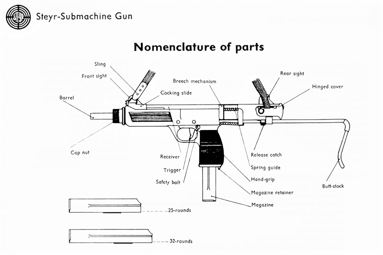
Developed in the late 1960s and introduced in 1969/70 the MPi 69 was Steyr’s entry into an already crowded European submachine gun market. Heavily influenced by the Israeli Uzi it had a bolt which telescoped over the barrel and fed from a box magazine that was inserted through a magazine well-come-pistol grip.
The MPi 69 weighed 6.5lbs (2.93kg) unloaded and had a polymer lower receiver into which a stamped metal upper inserted. Unlike the Uzi it had a collapsing, rather than folding stock, similar to the M3 submachine gun’s, and was cocked not by a handle but by pulling the sling (which was acted on the bolt) to the rear.
Steyr MPi 69 (Rock Island Auction Company)
The MPi 69 remained in production into the early 1980s when it was replaced by the improved MPi 81. Moving away from the slick-cocking ‘gimmick’ the MPi 81 had a conventional, non-reciprocating, charging handle on the left side of the receiver. The MPi’s polymer lower allows it to be a pound lighter despite being slightly longer as a result it also balances better than the standard Uzi carbine.
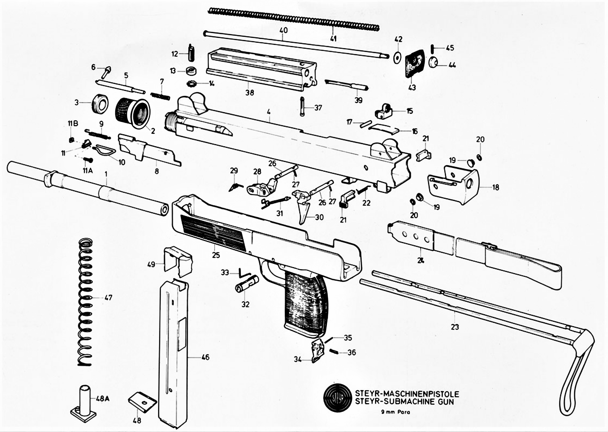
Steyr MPi 69 diagram (Steyr Manual)
The MPi submachine guns fed from 25 or 32 round box magazines and both guns had a heel-type magazine release paddle in the base of the pistol grip. They also shared their magazines with the AUG 9x19mm submachine gun conversion. Check out our earlier video on the Steyr AUG conversion here.
Steyr MPi 81 (Rock Island Auction Company)
The MPi submachine guns fire from an open bolt and had a 10in barrel and has a push through safety with settings for safe, semi and full auto and unlike the Uzi it does not have a grip safety – simplifying manufacture.
The MPi also has a progressive trigger which when set to full-auto will allow the user to fire semi when pulled to the first stage and full when pulled fully to the rear. While the MPi 69 had a cyclic rate of around 500 per minute, the MPi 81 increased this rate to ~750rpm.
Steyr MPi 69 disassembly diagram (Steyr Manual)
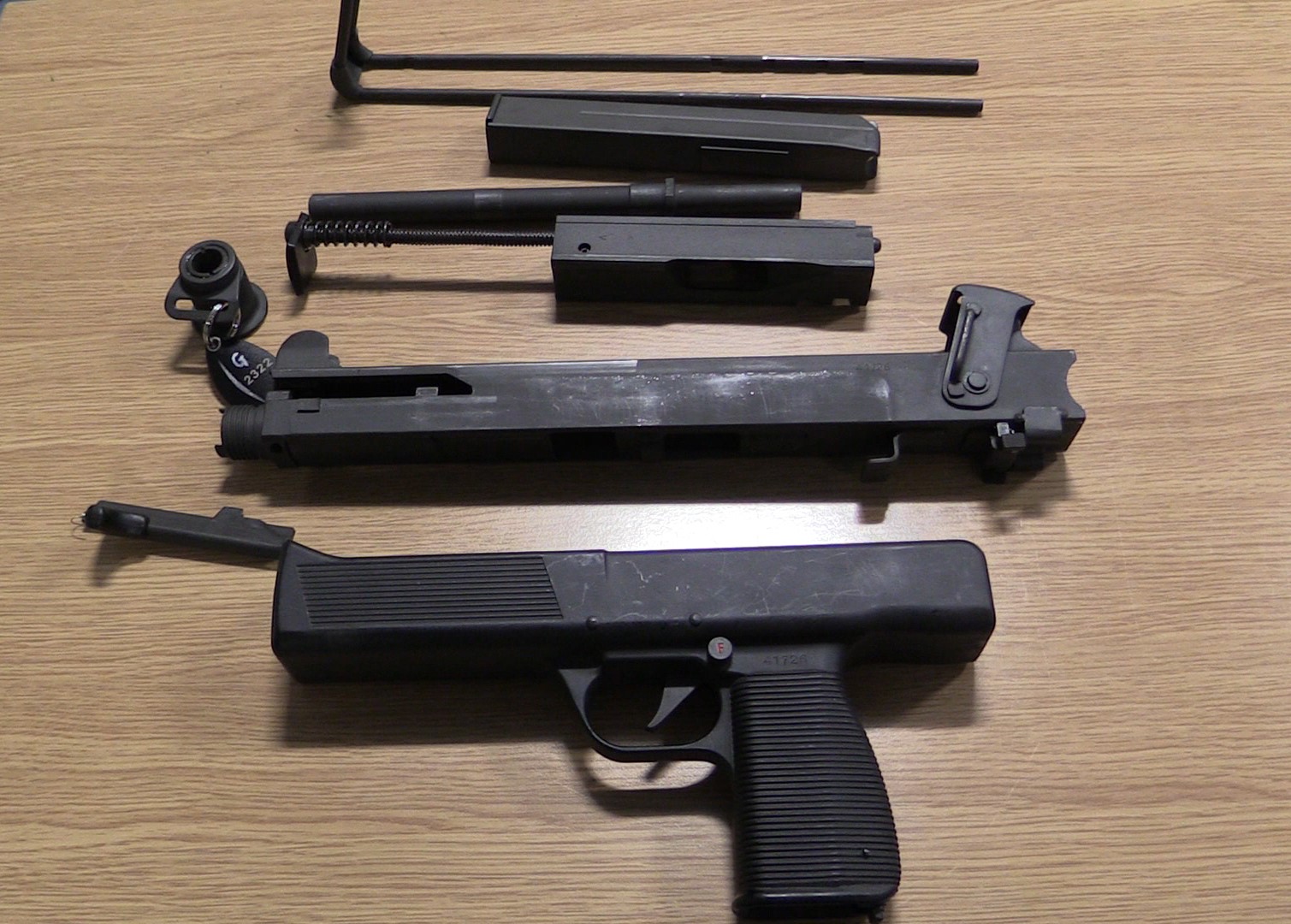
The MPi can be field stripped by simply rotating the receiver end cap up 90-degrees and pulling the bolt out the rear. The gun can be further stripped but the moulded polymer lower receiver can be difficult to remove from the upper. Like the Uzi the barrel nut is unscrewed to remove the barrel.
The MPi 81 fully disassembled (Vic Tuff)
It is unclear just how many MPi submachine guns were produced but they didn’t see any significant contracts beyond a few small sales to police forces and militaries.
The MPi 81 remained in production into the early 1990s when it was replaced by the smaller and more compact Steyr TMP in 1992. In turn the TMP design was sold to B&T a decade later.
Our thanks to the collection that let us take a look at this MPi 81 and to our friend Miles Vining for sharing some of his shooting footage of the MPi 81 with us, check out his video here and more of his work at www.silahreport.com.
This is the last of our series of videos/articles on the US Tanks of WWI, you can find all episodes here.
The MkVIII Heavy Tank holds the distinction of being the result of the first successful international co-operative tank project. Developed with input from British and American designers and engineers, intended to be equipped with British weapons and an American engine, with parts made in the US and Britain and to be assembled in France – a truly international undertaking. The MkVIII, sometimes referred to as ‘The International’ or ‘Liberty Tank’, owed its basic design to earlier British heavy tanks but a number of important changes were made.
Port side of a MK VIII heavy tank (US National Archives)
Intended for introduction in 1919, the war ended before the MkVIII could enter service and even before its French factory had been completed. It did, however, see some production and inter-war service providing the heavy tank backbone of the US’ tank force for many years.
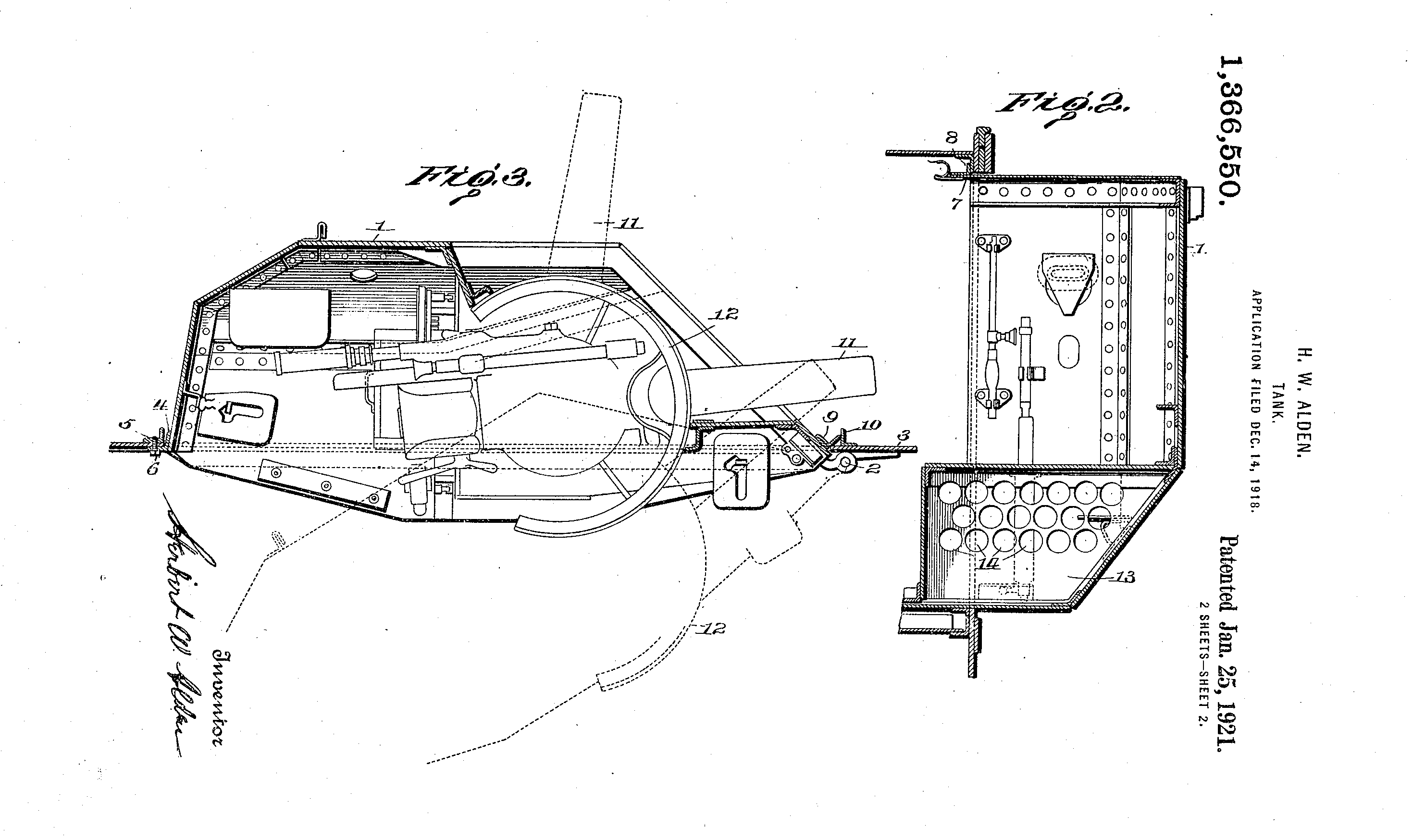
The design evolved from work by British Lieutenant G.J Rackham with later input from American engineer Major Herbert Alden. The MkVIII heavy was very much an evolution of the earlier British rhomboid heavy tanks but Rackham and Alden made some important improvements. Chiefly the redesigning of the tank’s sponsons which housed a pair of British 6pdr guns. While the tank was a foot narrower than its predecessors, the new folding sponsons could enabled the tank to be transported more easily by rail and to also, in theory, navigate narrow spaces. Alden patented this feature in December 1918 (US #1366550). Additionally, the commander’s ‘outlook turret’ positioned on top of the tank’s turret, which had vision slits on all four sides, was also retractable. Alden’s sponsons were hinged at the front and mounted on rolling bearings so they could pivot inwards.
Alden’s patent for his pivoting sponson (US Patent Office)
The MkVIII directly addressed several shortcomings of earlier British heavy tanks, firstly the engine was insulated in its own compartment to prevent exhaust fumes overwhelming the crew. A new ventilation system was also added with a fan keeping fumes out of the fighting compartment. Secondly, overall visibility was improved with protected vision and revolver slits and the addition of the tank’s commander’s turret.
Another important design change was the move to longer tracks, about 5 inches in length, which required a dozen less links than the MkV. Each of the links was shallowly stamped to increase its strength. In terms of armament the MkVIII was designed as solely ‘male’ – with guns in its sponsons, not machine guns – however, with a raised tower on the tanks roof this provided positions for five machine guns in hemispherical ball mounts. Two more machine guns could be mounted in the tank’s hull doors located behind the sponsons. The ammunition for the 6pdr guns was held in a central ammunition storage box but the sponsons also had shell storage space surrounding the guns themselves.
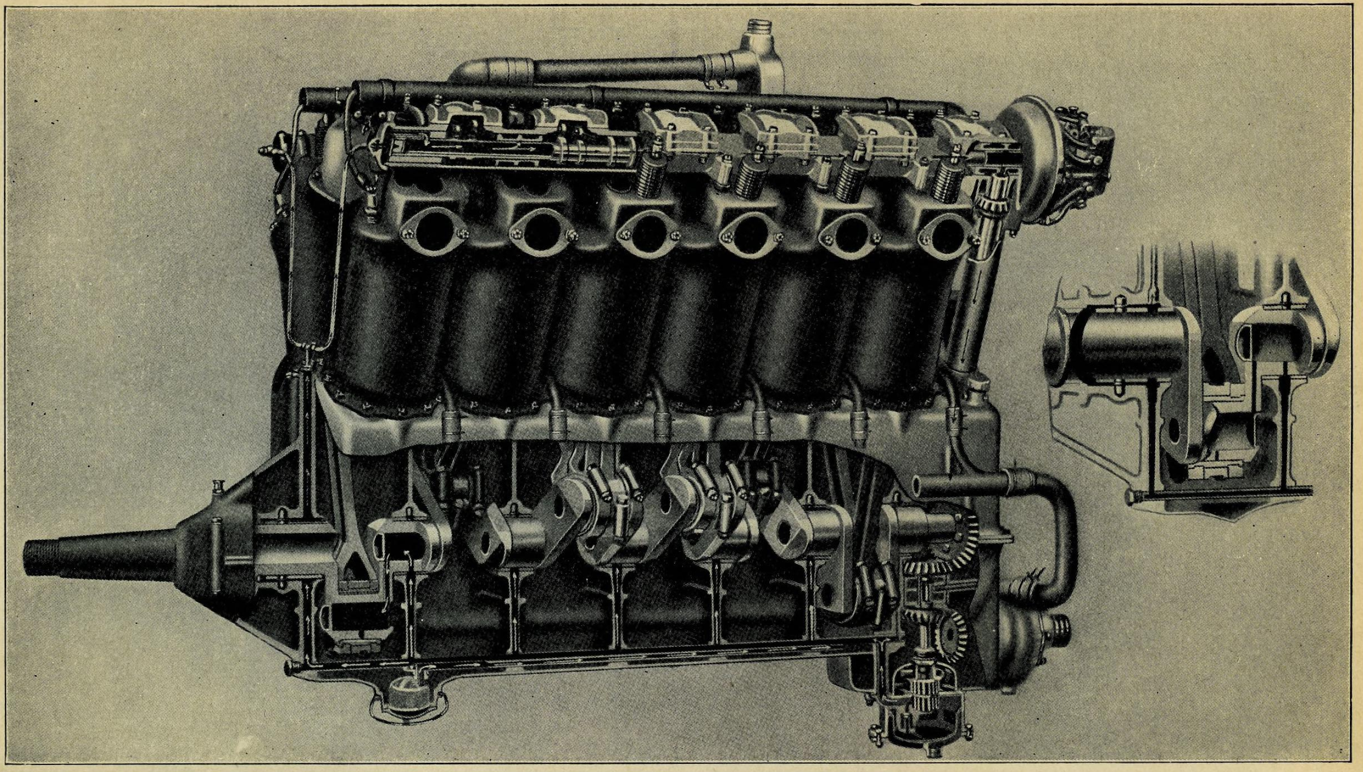
The MkVIII’s V12 engine (US Army Preliminary Handbook for the MkVIII)
The 37 ton tank was to be powered by an American V12 aircraft petrol engine manufactured by the Liberty company. Although a cheaper, water-cooled Liberty was eventually used in the American tanks. The British developed a similar 12 cylinder engine from Ricardo. This, in theory, produced 300 horsepower with a top speed of just over 6mph and a range of just under 40 miles. The MkVIII’s engine was moved from the centre of the tank to a separate engine compartment at the rear of the tank. This not only reduced engine heat and fumes in the fighting compartment but also made communication easier. Some sources also suggest that the MkVIII was the first tank to have an electronic intercom system.
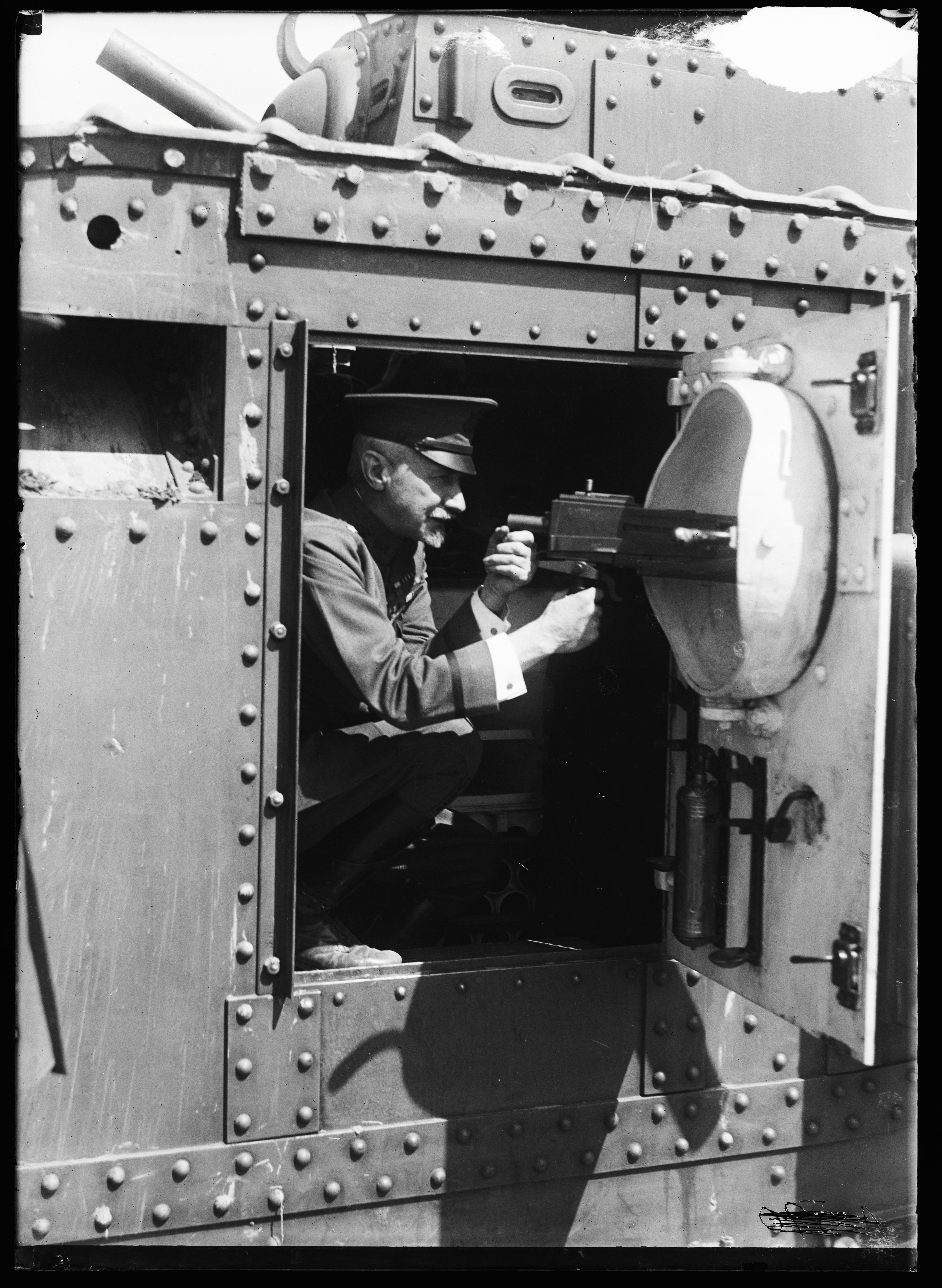
An officer illustrates how one of the tank’s ball mounted machine guns worked – the gun itself is an M1919 tank machine gun (US Library of Congress)
The American Preliminary Handbook for the MkVIII listed the tanks as being equipped with 7 ‘Hotchkiss .303-inch machine guns’, these are likely to be Hotchkiss Portative MkI*s popular in British service. In US service, however, the tanks were likely later equipped with the new Browning M1919 Tank Machine Guns. The tank carried 182 rounds of 6pdr ammunition and an additional 26 smoke rounds as well as 21,000 rounds of machine gun ammunition to keep the 7 machine guns fed.The tank’s armour was also increased lightly from the previous MkV, with 16mm of frontal armour and between 10 and 12mm at the sides. Less vulnerable areas had armour 6mm thick.
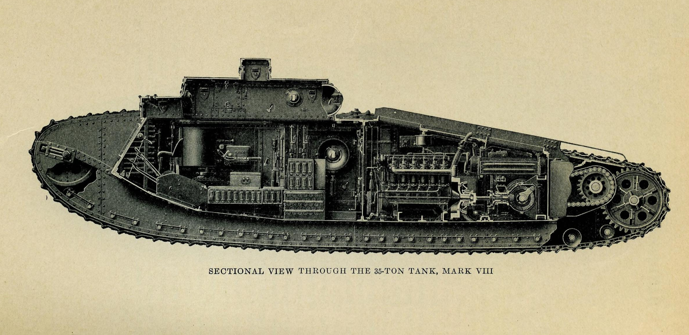
A partial cutaway view of the tank (US Army Preliminary Handbook for the MkVIII)
The American MkVIIIs were initially planned to be manned by an eleven-man crew made up of a driver, commander, two gunners and two loaders to man 6pdrs, four machine gunners and a mechanic. Later crew complements probably dispensed with two of the machine gunners as the US MkVIIIs operated during the inter-war period dispensed with two of the midships machine guns. The British crew was planned to be smaller with 8-men fighting the tank, made up of a driver, commander a pair of gunners and loaders for the main guns and two machine gunners who were tasked with manning the tank’s various machine guns. Impressively the 34 feet long tank also had room for as many as 22 infantry to be transported.
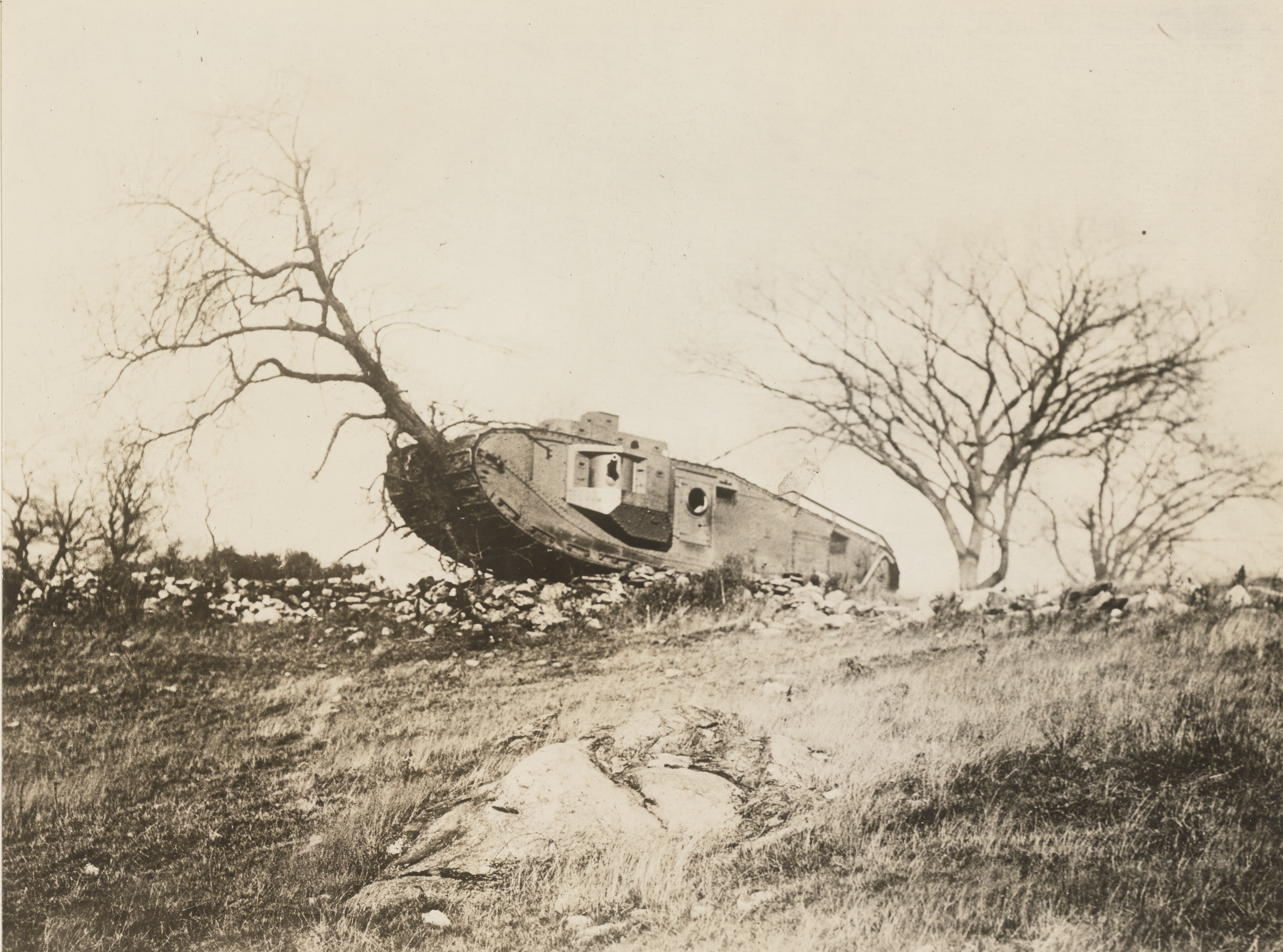
A MkVIII demonstrating its power by destroying a tree during testing (US National Archives)
As an allied collaborative project the production of parts was to be a collaborative effort. Britain was to contribute armour plate, structural frame work and armament. The American contribution was to include the automotive parts including the engine, brakes, drive sprockets, gears and transmission.
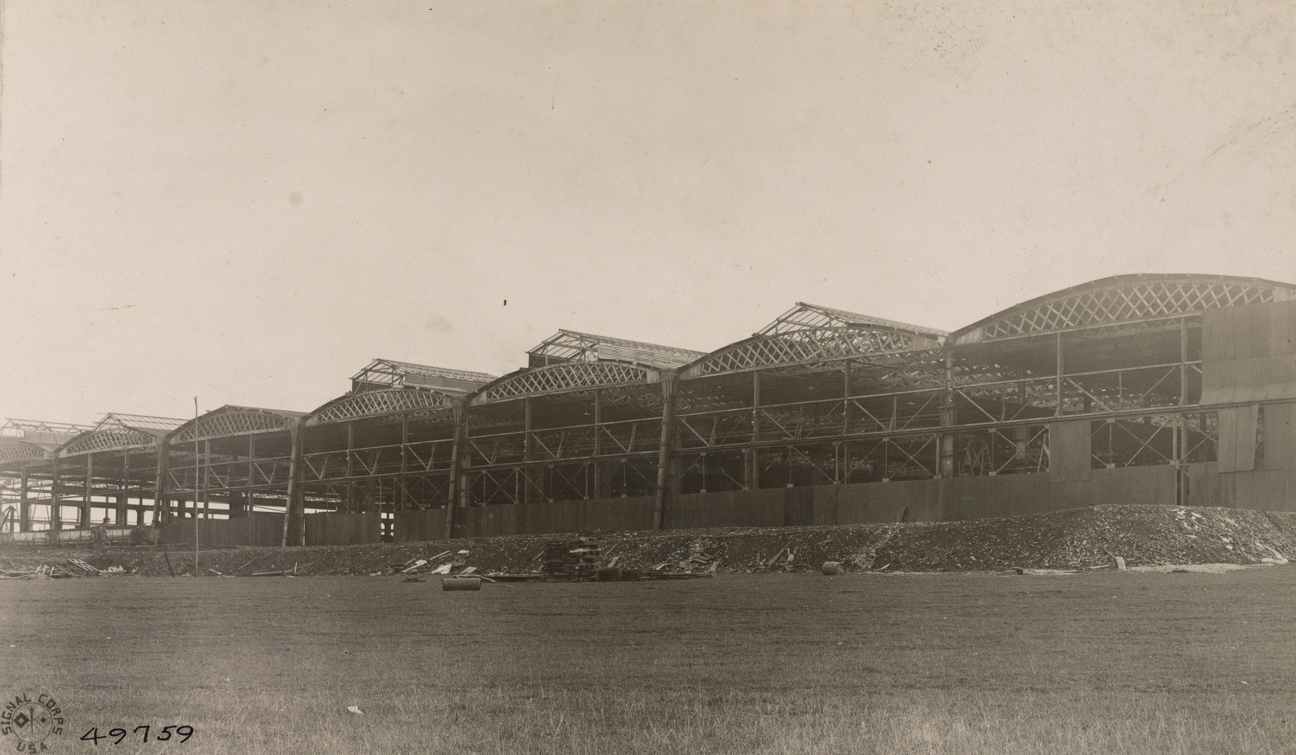
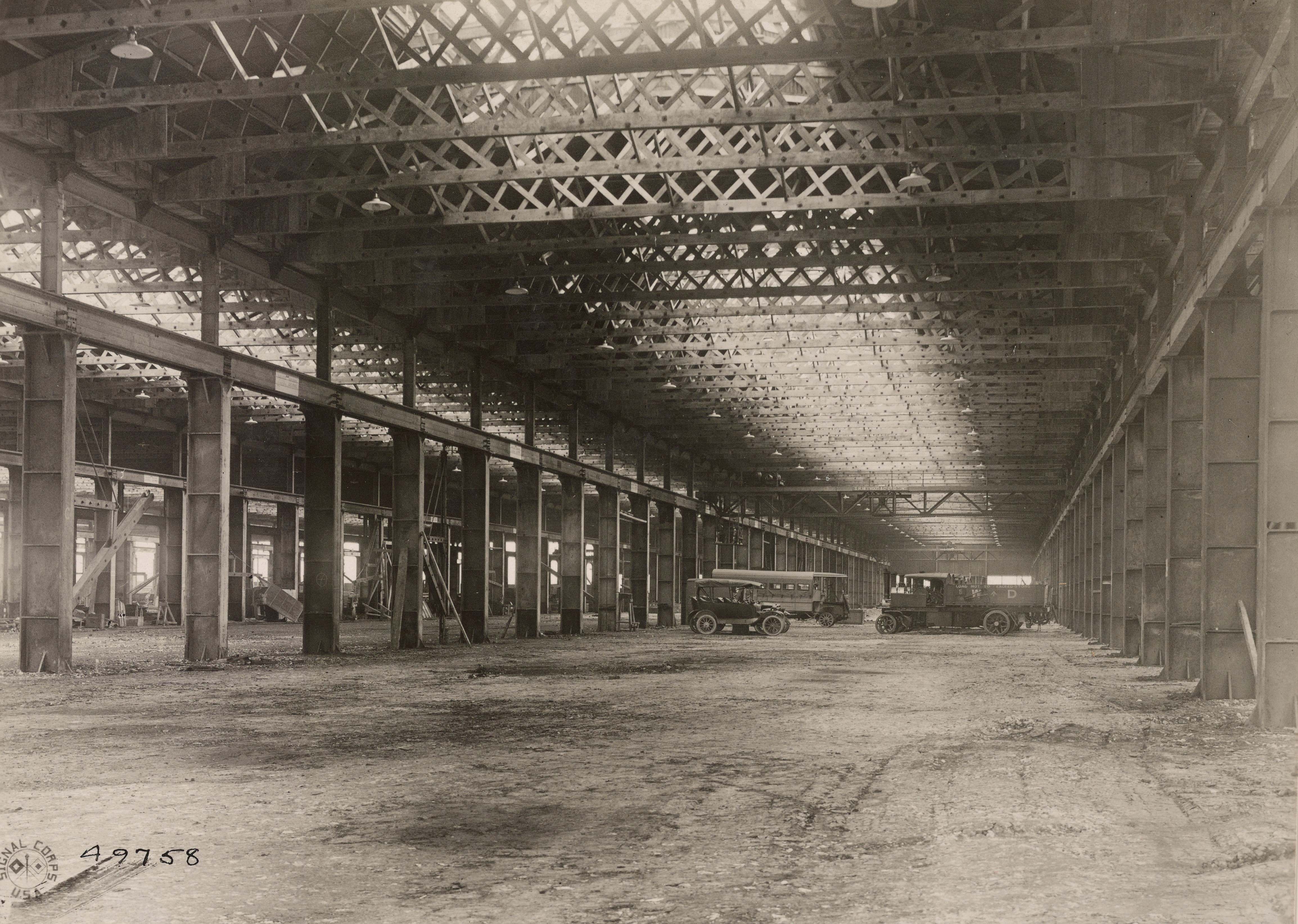
The French were largely uninterested in British heavy tanks and their primary contribution to the MkVIII project was a factory site near the village of Neuvy-Pailloux, 165 miles south of Paris, in central France. Critically located well away from the fighting on a main rail route north, through Issoudun. Construction of the impressive factory appears to have begun in early 1918, with the framework of seven long production halls and the installation of a powerplant and generators and the building of railway sidings completed before the armistice in November 1918. Production barely got underway in Britain, let alone in France. Contemporary photographs taken in January 1919, by the US Army Signal Corps show the factory with its roof in various stages of completion, its shop floors unfinished and empty and open to the elements. The factory would eventually be completed and used by the French army as an artillery park and later a maintenance depot.
The incomplete Neuvy-Pailloux factory c.1919 (US National Archives)
The oringal plan was for the tank parts to be shipped across the channel and the atlantic through France’s western coastal ports to be shipped by rail to Neuvy-Pailloux where they would be assembled into working tanks. It was envisaged that the workforce would be made up of Chinese labourers with British and American foremen and managers.
Inside the incomplete factory (US National Archives)
As many as 3,000 tanks were planned for 1919. The British intended to build 1,450 MkVIIIs of their own use in addition to the 1,550 to be produced for general allied use. The British tank parts were to be manufactured in Manchester, by the various workshops of the Manchester Tanks Association, and in Glasgow, by the North British Locomotive Company. Mass production in Manchester never got underway and the initial British MkVIIIs were built in Glasgow – just 24 are believed to have been built, all but six of these were scrapped almost immediately. The first American tanks were assembled by the Locomobile Company of Bridgeport, Connecticut. The American-assembled MkVIII completed acceptance trials in the spring of 1919. With the end of the war the US order was reduced from 1,500 to 100. 100 sets of hull components were bought from Britain and assembled with corresponding American parts at the Rock Island Arsenal.
A US MkVIII at Camp Meade, c.1921 (US National Archives)
The MkVIII was the last of the British rhomboid heavy tanks. The handful of British MkVIIIs built never entered service but the 100 American tanks along with American built M1917s, MkV Heavies and Renault FTs brought back from France, formed the backbone of the US Tank Corps throughout the early inter-war period. The US MkVIIIs remained in use as training tanks until 1932. Today, just three are believed to survive; two in the US and one in Britain.