Matt had the pleasure of attending the Autumn 2019 Soviet Threat event at Hack Green Nuclear Bunker in Cheshire at the weekend and spoke to many of the reenactors and collectors attending the event. Check out our earlier video about the event here.
One of the people Matt had the chance to speak to was Simon of the Rifleman Moore YouTube channel. Simon is a collector of uniforms and kit and part of the MECo group of collectors and reenactors. Simon was kind enough to film a quick video with Matt and discus his kit.
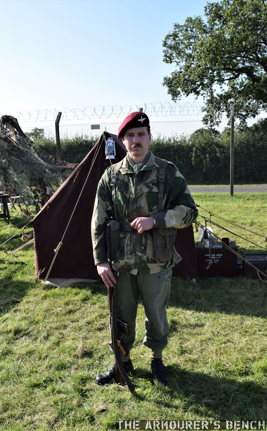
At Soviet Threat he was portraying a member of the British Army’s PARA’s as they would have been dressed and equipped circa 1964 – twenty years on from Operation Market Garden, which took place 75 years ago this year.
A full-length photo showing Simon’s portrayal of a 1960s PARA, complete with SLR (Matthew Moss)
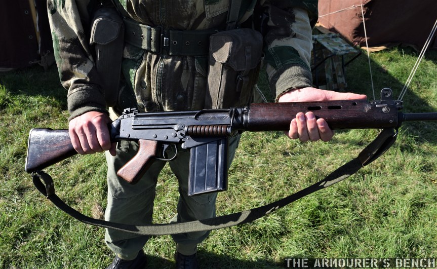
Here’s a closer look at the deactivated L1A1 Self-loading Rifle Simon completed his portrayal of a period PARA with.
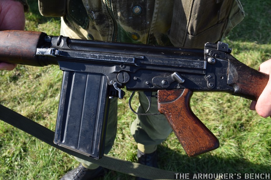
A nice example with period-correct wooden furniture and rifle sling (Matthew Moss)A closer look at the rifle’s markings (Matthew Moss)
The rifle was an Royal Small Arms Factory Enfield-production L1A1, inch pattern semi-automatic adaptation of the FN FAL, manufactured in 1958, as attested to by it’s UE58 prefixed serial number.
Many thanks to Simon for taking the time to speak to us and run through his uniform and kit. Check out his channel here.
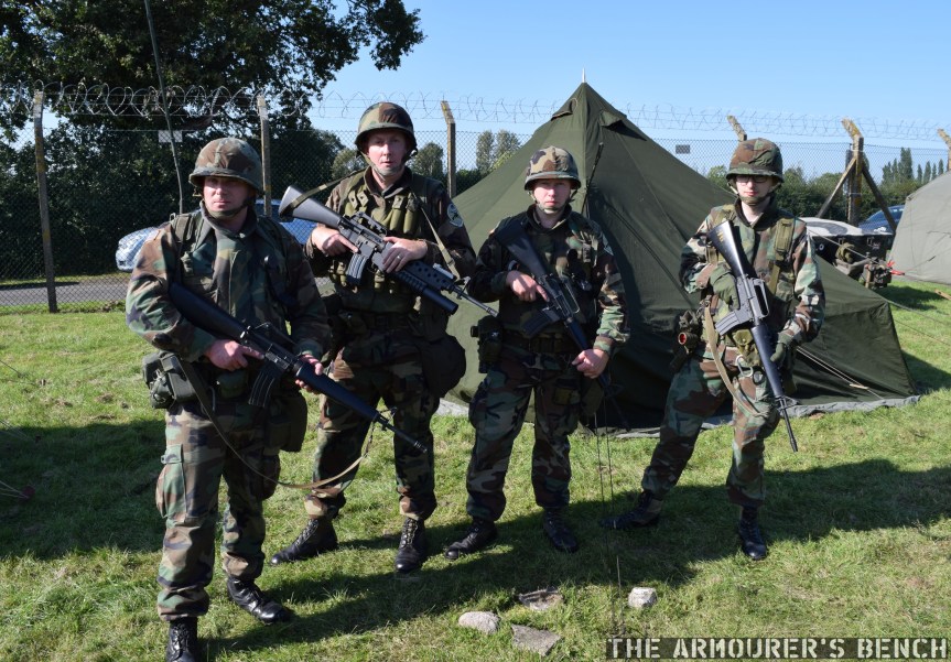
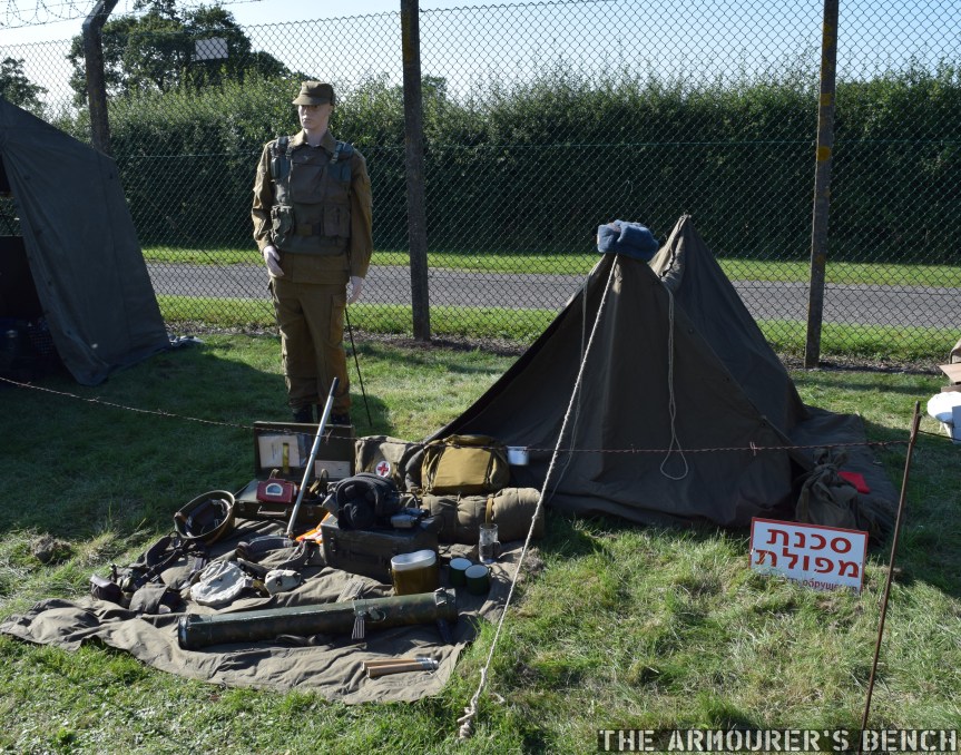
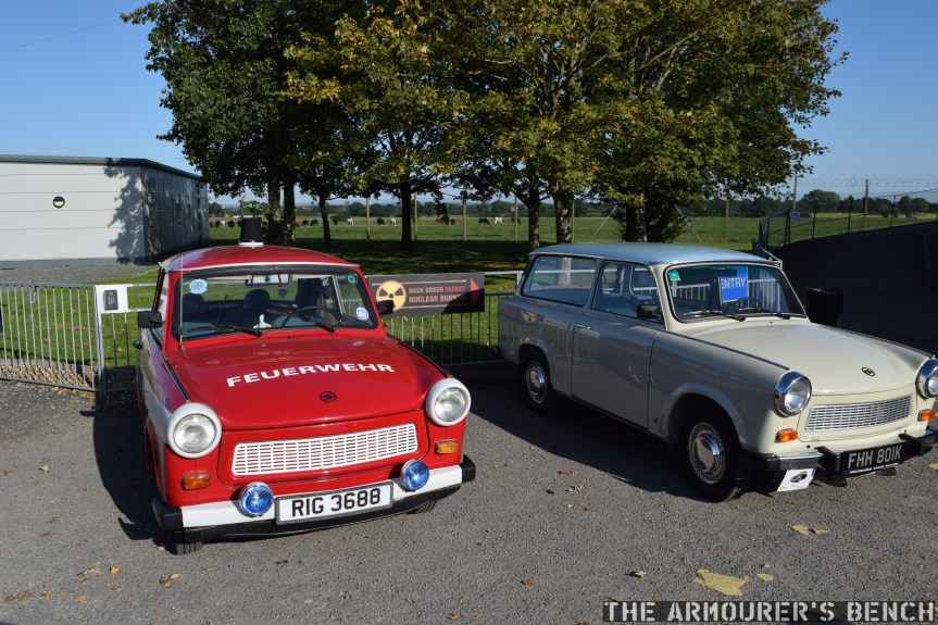
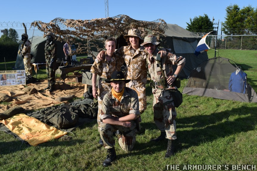
This weekend I visited the Hack Green nuclear bunker in Cheshire, UK. They have a bi-annual Cold War history event called Soviet Threat where reenactors and collectors are invited down to display their kit. I had the pleasure of meeting to some really interesting people and seeing some cool vehicles and kit.
I spoke to Lucy, the Hack Green Bunker museum’s curator but sadly had some sound problems. Hopefully, we’ll get to speak to Lucy about the museum in more depth in the future! I also spoke to a number of the groups and individuals attending and we’ll have a couple more videos coming up.
Here’s some photos from the event:
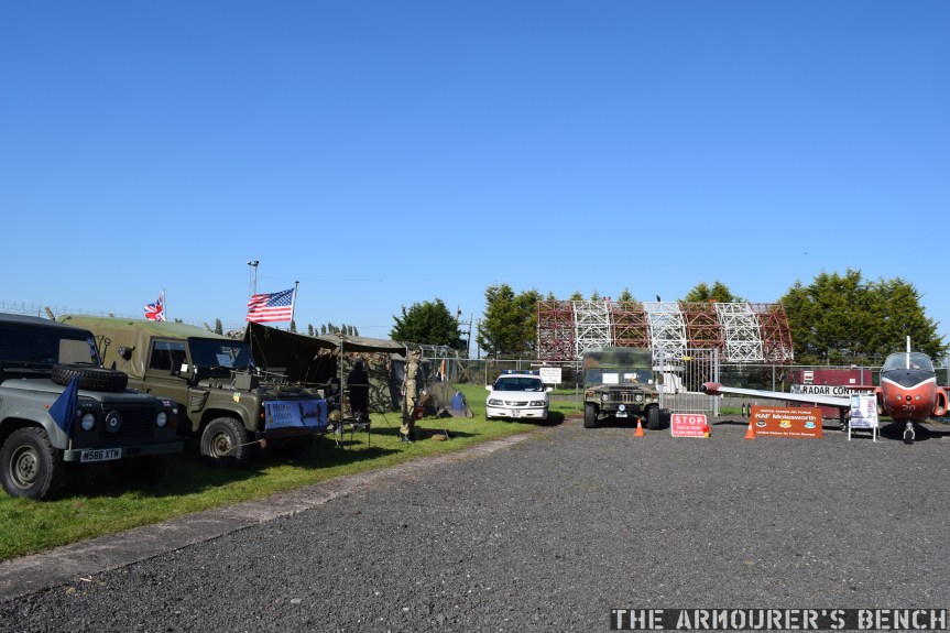
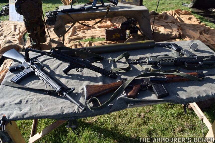
Some of the vehicles on display at Soviet Threat, including a HMMWV and a jet trainer (Matthew Moss)Members of Lazy Company prepare for guard duty (Matthew Moss)A Soviet camp display (Matthew Moss)A pair of East German Trabants (Matthew Moss)Some of the local lads from a Gulf War reenactment group (Matthew Moss)Some deactivated weapons from the Gulf War display (Matthew Moss)
The Boeing Bomarc was the world’s first long-range surface to air missile and despite its shortcomings remain in service for a decade. It was an extremely ambitious project and is a Cold War weapon that few today are familiar with.
In the late 1940s, Boeing began work on a surface to air missile – then described as a ‘pilotless interceptor’. The project was code-named MX-1599 and the Michigan Aerospace Research Center (MARC) joined Boeing to work on the programme.
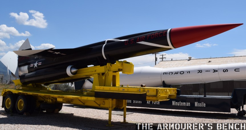
Boeing BOMARC at Hill Aerospace Museum (Matthew Moss)
The MX-1599 was to be a long-range supersonic nuclear-tipped surface to air missile (or SAM), detonated by a proximity fuse. The missile went through a number of official designations as it was developed during the 1950s – finally becoming known as the Bomarc – an acronym of Boeing and Michigan Aerospace Research Center.
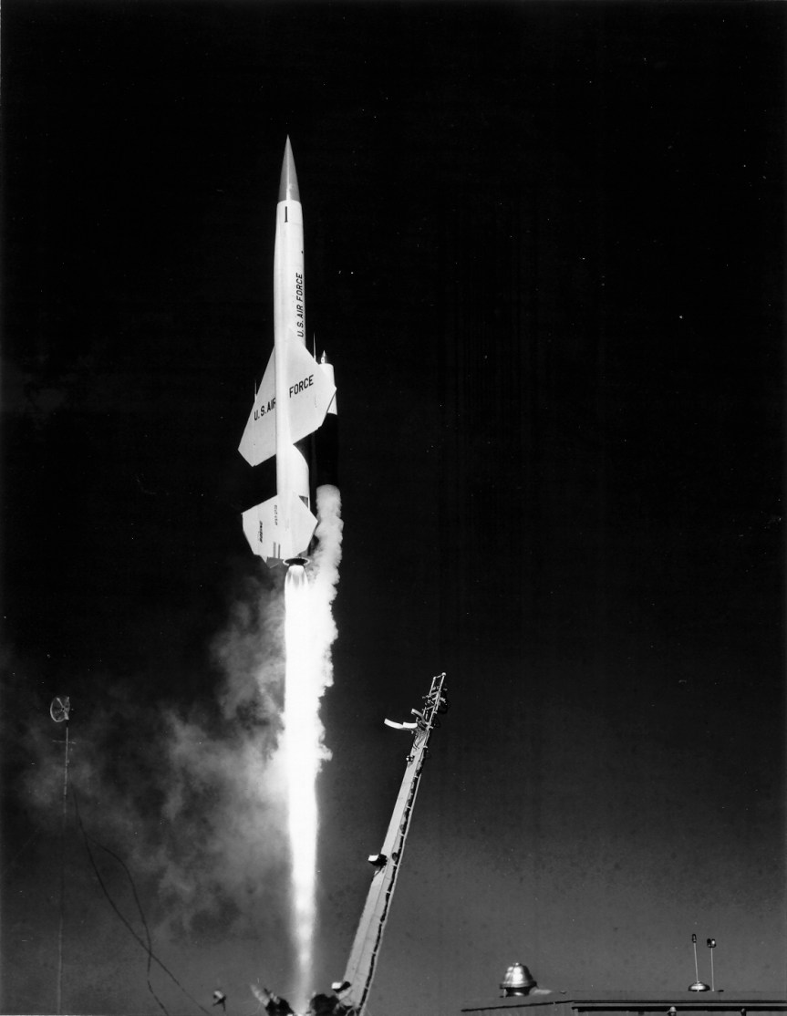
The Bomarc was launched vertically using rocket boosters, before its main ramjet engines took over, enabling it to cruise at Mach 2.5 (approx. 1,920 mph). The initial Bomarc A had a range of 200 miles with an operational ceiling of 60,000 feet.
It was ground controlled using NORAD’s Semi-Automatic Ground Environment (SAGE) system until it neared its target, when an onboard radar, a Westinghouse AN/DPN-34 radar, took over.
The Bomarc could be tipped with either a 1,000 lb conventional high explosive or low yield W40 nuclear warhead. These were detonated by a radar proximity fuse. The W40 had a yield of up to 10 kilotons, able to destroy entire formations of aircraft.
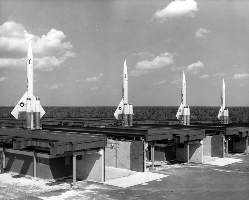
BOMARC Site No. 1 at McGuire Air Force Base (USAF)
The missile had a wingspan of just over 18 feet or 5.5metres, it was 45 feet or 13.7 metres in length and weighed approximately 16,000 lbs (7257 kg) on launch. The Bomarc’s first flight took place on 24th February, 1955.
The USAF intended to use the missile to engage incoming Soviet bomber formations and ICBMs. Originally planning for over 50 Bomarc launch sites, but only one was operational by 1959 and only eight were operational by the early 1960s. The upgraded Bomarc B was developed in the early 1960s, with an improved radar, a Westinghouse AN/DPN-53, and a greater maximum range of 430 miles, as well as a higher operational ceiling of 100,000 feet.
The Bomarc was stored horizontally in specially built semi-hardened bunkers and kept fuelled and ready to launch at a moment’s notice. When targets were detected the missile would be raised and launched vertically.
One of the dangers of keeping the missiles fuelled became clear in June 1960, when a nuclear-armed Bomarc A caught fire exploding the onboard tank and contaminated part of McGuire Air Force Base with melted plutonium. Despite this the missiles remained operational for over a decade with the first sites being deactivated in 1969 with the last stood down in 1972.
BOMARC launching (USAF)
While the Bomarc missiles were the world’s first operational long-range anti-aircraft missile they were too slow to achieve operational readiness to keep pace with the rapidly changing nuclear threat – as both superpowers transitioned from bomber to ICBM-focused strategies. They were expensive to manufacture and difficult to maintain at readiness. In the late 1950s the Bomarc also embroiled in a war of words with the US Army arguing their short range Nike Hercules (SAM-A-25/MIM-14) missile was more effective. The Hercules remained in service through to the 1980s, albeit as a air defence missile – rather than targeting soviet ICBMs or bomber aircraft.
The Bomarc was an ambitious project when it began in the late 40s, but with technology and cold war nuclear strategy rapidly evolving the Bomarc was almost obsolete before it became operational. A total of 570 Bomarc missiles were built between 1957 and 1964 with the US and Canada (which led to considerable political controversy) being the only countries to deploy them.
I hope you guys enjoyed this look at the Bomarc, we’ll have a few more videos on missiles in the future.
IM-99A/B BOMARC Missile, Boeing, (source) Nuclear Weapons of the United States: An Illustrated History, J.N. Gibson, (1996) Nike Historical Society (source)
Supersonic Guardian, Boeing film, c.1960 (source)
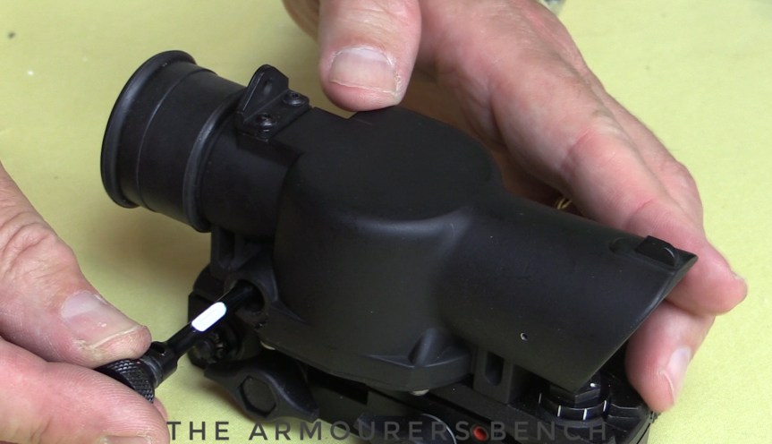
Vic continues his Surplus Zone series with a look at the British SUSAT sight, principle by Britain on the SA80 and by Spain with the CETME Model LV and AMELI. In this episode Vic shows us how to refit a SUSAT with new elements.
The Sight Unit Small Arms, Trilux was developed in the late 1970s by the Royal Armaments Research Development Establishment. It is a 4x optic which uses a radioactive tritium light source, for use in low light conditions, which due to radioactive decay has to be replaced every 8-10 years.
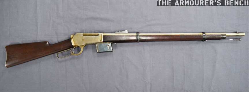
The rifle we’re examining is one of dozens of designs sold by the Brownings to the Winchesters Repeating Arms Company during their long relationship. This design dates from the early 1890s and represents one of Browning’s numerous attempts to move away from the tube magazine-fed designs favoured by Winchester.
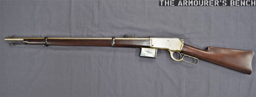
The prototype is based around the lever-actuated vertically sliding locking block patented by Browning in May 1884 and first used by Winchester in the Model 1886. The rifle itself is in the ‘military musket’ configuration with full-length handguards, military sights, a cleaning rod and able to mount a bayonet.
Right side of the rifle (Matthew Moss)
The rifle is chambered in a .45 calibre cartridge, likely .45-70, and weighs just over 9lbs. Browning patented the design of the rifle and magazine in August 1891, with the patent being granted in December (US #465339). It is attributed to John Moses Browning and his younger brother Matthew S. Browning.
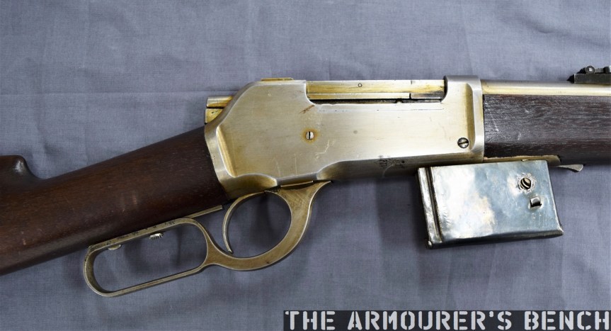
The most interesting feature of the rifle is its detachable box magazine. The magazine is held in place by a spring-loaded catch at the front of the magazine which locks against a tab in the magazine’s wall.
A close up of the magazine well, note the added metal lip of the front of the well, not a part of the receiver (Matthew Moss)
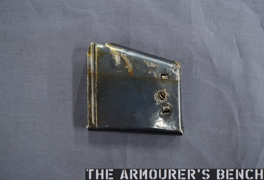
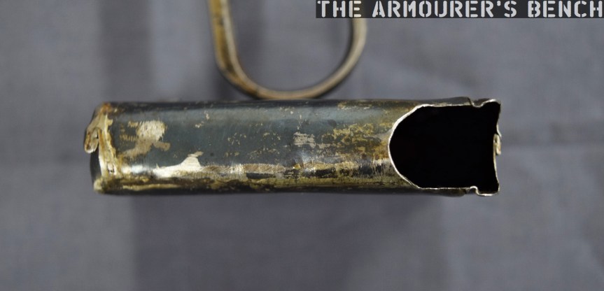
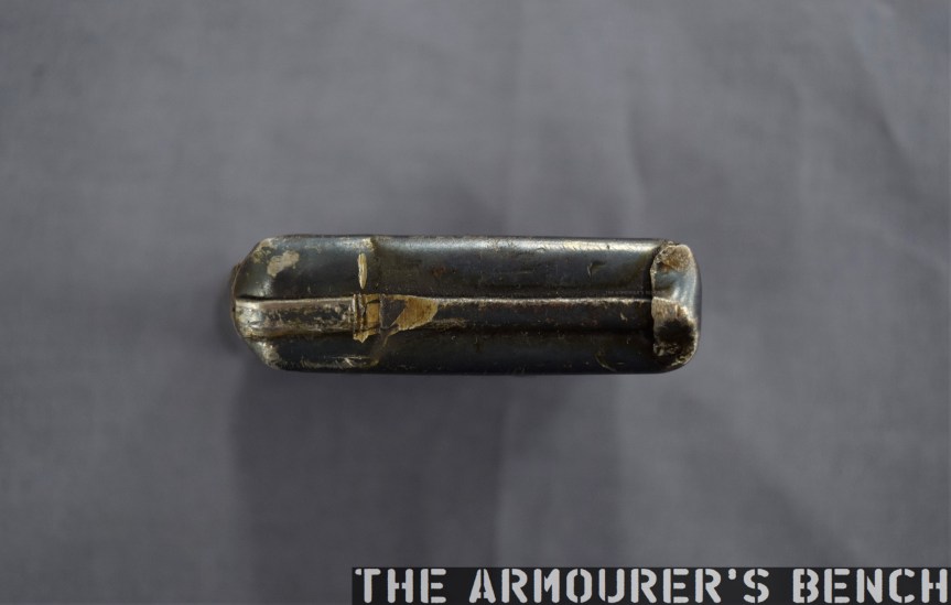
It differs from the box magazines previously developed by James Paris Lee, which Lee begun developing in the mid-1870s (see examples listed below). It’s a simple design with a follower powered by a coil spring. The prototype mag itself is made from pressed metal and is held together with some rough welds. Unlike the magazines we’re familiar with today, the top of the Browning’s magazine is almost entirely enclosed with only a small opening at the rear. The rounds would be loaded nose-first with their rims sliding into the channel at the rear of the magazine.
Close up of the magazine removed from the rifle – right side (Matthew Moss)A view of the top of the magazine with the small opening and notch for the cartridge rime visible (Matthew Moss)
The single-stack magazine appears to hold around five rounds, with Browning’s patent supporting this. The position of the magazine, in front of the action – not below it, is a hint at how it worked. An almost fully enclosed magazine does have its advantages – it would have prevented dirt from entering the mag and it also overcame the need for feed lips which were susceptible to damage, one of the elements which took Lee some time to perfect.
A close up of the front wall of the magazine, note the locking notch (Matthew Moss)
So How Did The Magazine Work?
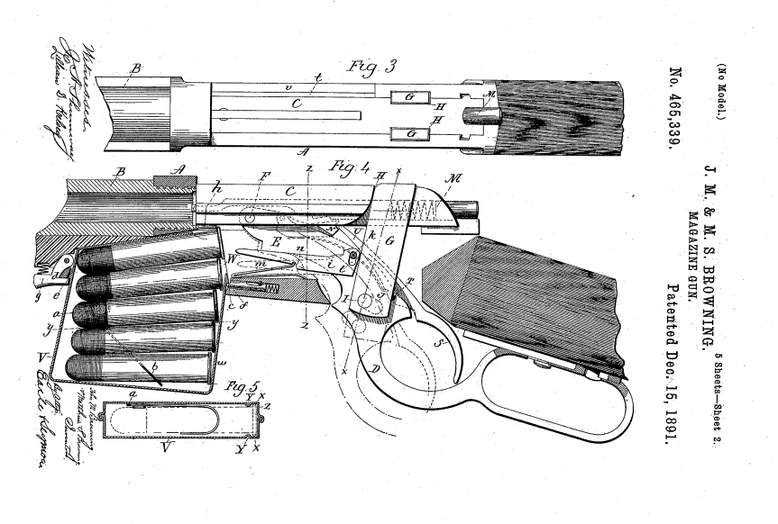
There is a shoulder on the underside of the bolt which caught the rim of the cartridge which was protruding from the magazine. The bolt pulled the cartridge backwards, out of the magazine and onto a cartridge lifter. As the lever reached its full forward travel the lifter then elevated the round up into line with the breech. When the lever was cycled back again the round was pushed off the lifter and chambered, just as in a normal tube-fed Winchester. As the lever reached the end of its return travel the locking block rose to locked the action.
The Browning’s 1891 patent for the magazine, note ‘h‘ is the shoulder which pulled rounds out of the magazine (US Patent Office)
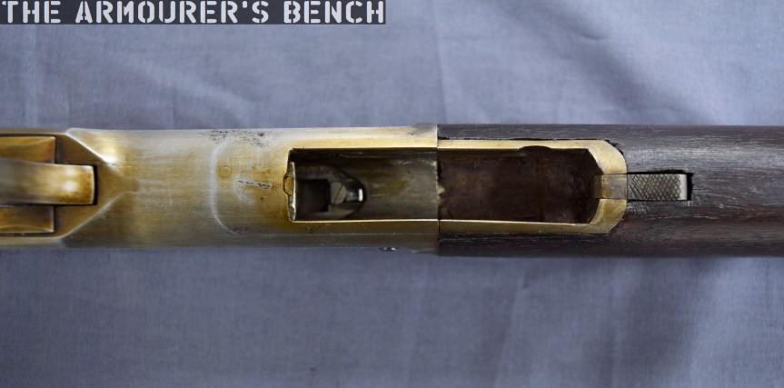
The prototype has a sliding safety bar that locks the lever and blocks the trigger. The trigger differs from the Model 1886 as it is integrated with the lever. In the photograph below we can see the locking block descended, with the lever forward, and the breech block to the rear with the action open. We can also see the striker assembly at the rear of the bolt. The striker cocks on closing when the lever is returned rearward.
The rifle with its action open, bolt o the rear and lever forward. Note the striker assembly at the rear of the bolt (Matthew Moss)
It’s quite an exposed action, with the entire top of the action open. With the action closed in the photograph below we can see the extractor running along the right side of the bolt.
A close up of the rifle’s receiver which is still ‘in the white’ (Matthew Moss)
It’s clear from the design of the magazine that Browning didn’t intend the rifle to be reloaded with stripper clips, although single loading of the rifle itself (not the magazine) would have been possible. When compared to other contemporary system this would have been somewhat of a disadvantage compared to Lee’s magazine’s later loading with chargers and stripper clips. However, from examination of Browning’s 1891 patent his intention becomes clear, the patent explains that he intended for the magazine itself to be replaced:
“One magazine may be readily removed from the gun and another introduced in its place, so that the person, using the arm may have at hand several magazines to be interchanged as the cartridges from one magazine are exhausted.”
This is a concept that wouldn’t be accepted by militaries for decades. Winchester purchased the rights to the design but this was one of many designs Browning sold the company which never saw production. The design and prototype are fascinating and represent one of Browning’s lesser-known concepts.
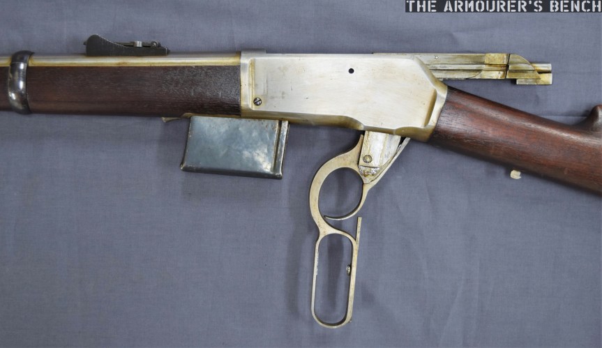
Left side profile of the rifle (Matthew Moss)
This rifle is a unique prototype and it was a true honour to examine it. It’s now on display at the newly refurbished Cody Firearms Museum, at the Buffalo Bill Centre of the West. The new museum is phenomenal and well worth a visit. Our thanks to the museum for allowing us to film items, like this one, from the museum’s collection.
The Vickers Gun is an iconic weapon, developed from the Maxim and adopted by the British in 1912. It served for over 50 years in conflicts all around the world. In this video, we’re lucky enough to have Richard Fisher of the Vickers Machine Gun Collection and Research Association shows us how to disassemble a the gun and talk us through its internals.
Big thank you to Rich for taking the time to help with this video and provide the voice over explaining the process! We’ll have more videos on the Vickers Gun in the future! Check out Richard’s work over on the Vickers Machine Gun Collection and Research Association’s site here.
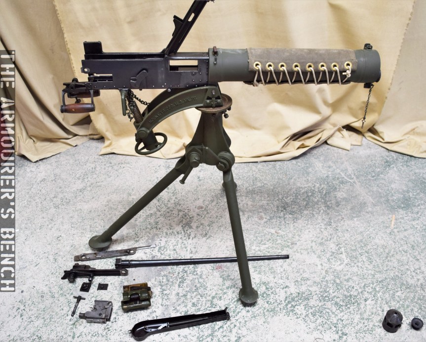
I’ll let Rich explain the disassembly process in real time in the video but here are a couple of photographs of the gun disassembled:
The Vickers gun field stripped (Matthew Moss)
This is the gun in its fully field stripped condition, with lock still assembled, but with its fusee spring and cover off and its barrel and action removed. Just below the barrel is the feed block.
Here’s the Vickers Gun’s lock disassembled into its 14 component parts:
The gun’s disassembled lock (Matthew Moss)
This photo gives us a good look inside the receiver with the barrel, action and side plates removed, The spade grip assembly simply folds down to allow the action and barrel to be slide out of the gun.
Once the action and barrel is removed you can look straight through the receiver and down through the water jacket (Matthew Moss)
Finally, here’s the gun reassembled and ready for action.
The gun fully reassembled (Matthew Moss)
Thanks again to Richard for his help with this video, it was great to collaborate and hopefully we’ll have more videos with Rich in the future. Please check out the Vickers Machine Gun Collection & Research Association’s site to find out more about what they do. They have some wonderful resources, including a comprehensive collection of manuals, for not just the Vickers but also the wider British Army from the past 100 years. You can also order copies of the brilliant instructional posters which were featured in the video over on the the associations website too!
We’ve looked at a few cutaways in the past, today we’re going to take a look at a Lee-Enfield Rifle No.4 cutaway.
One of the main drawbacks of the venerable SMLE was that it was expensive and time consuming to manufacture. The No.4 was an attempt to address this. It evolved from the experimental No.1 MkV and MkVI which were trialled in the early 1920s. The key mechanical change was that the barrel was free-floated and had a heavier profile to deal with expansion of the stock. The No.4 also had a new rear aperture sight mounted further back on the receiver giving a better sight picture and a longer sight radius.
Close up of the Rifle No.4 Instructional Cutaway’s receiver (Matthew Moss)(Matthew Moss)
With this cutaway we get a look inside the butt trap, which has a pull-through and oil bottle inside, then as we move to the action we get a look at the rifle’s trigger, sear, sear spring and magazine catch. If we look closely we can see the bolt head catch. The magazine has also been cutaway, with the magazine follower spring just visible.
This cutaway rifle has had all of the wood around its receiver removed, so we can see the magazine housing floor plate and the point where the retaining screw attaches to the trunnion. As we move along we get a look inside the chamber where the outline of the cartridge neck is easy to see and we can also see the barrel’s rifling too.
Rifle No.4 Instructional Cutaway (Matthew Moss)
Down near the muzzle the rifle’s upper retaining band and the hand guard have been cutaway to show the barrel inside. The No.4 was adopted for service officially in November 1939 and just over 4 million were made during WW2. We’ll have a full, more in-depth video on the No.4 in the future.
Check out our earlier videos featuring cutaways including the Pattern 14 and the CETME AMELI.
This week TAB hit 4,000 subscribers! Thanks for all your support over the last couple of years. I filmed this update on Tuesday during a recent research trip in the south of England. I visited Fort Nelson near Portsmouth and thought I’d film a quick update while I stopped for a break.
Today, we have a short video looking at Fort Clinch, a fort built at the mouth of the St Mary’s river in North eastern Florida. The pentagonal masonry fort defends the strategic position on Amelia Island, at the mouth of the river and Cumberland sound.
Fort Clinch (Steve Moss)
While the site had been fortified by the Spanish in the 1730s, construction of the present fort began in 1847 after the end of the Second Seminole War. Built as part of the Third System of coastal defences, which began in the 1820s and was characterised by building thick masonry walls. Clinch is one of the smaller forts that were built to defend less important harbours. Named after General Duncan Lamont Clinch, the fort wasn’t fully completed until 1869.
During the civil war it was originally held by the Confederacy before they abandoned it and it was taken over by the Union in spring 1862. The Union then set about finishing the fort. While some sources suggest it was designed to mount as many as 70 guns, it was never fully equipped but we can see that it has mounts and barbettes for around 40 guns on its ramparts.
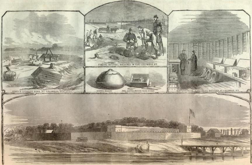
An illustration of the incomplete Fort Clinch featured in a March 1862 copy of Harper’s Weekly
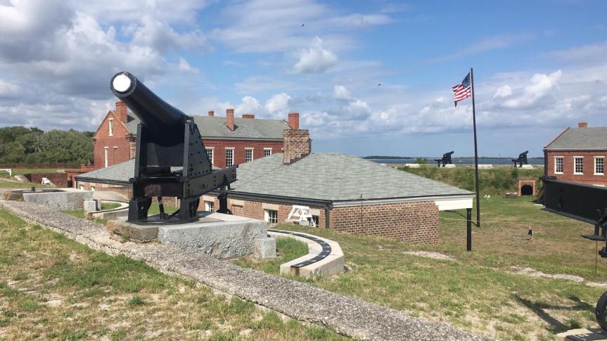
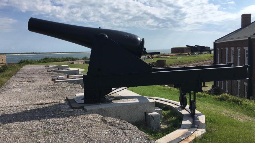
Today, the fort has a handful of Rodman guns in place. The guns appear to be mounted on front-pintle barbette carriages. Beneath the guns are ammunition casements; powder rooms and shot stores, the holes for bringing up ammunition can still be seen.
Rodman guns were a staple of US coastal forts during the late 19th century, designed by Thomas Jackson Rodman, they were hollow cast and much stronger than earlier, traditionally cast guns. They were produced in a variety of calibres ranging from small 8 and 10in guns to huge 15 and even 20in guns. They were designed to be fired from behind a parapet, giving the crew some protection, the parapet at Fort Clinch is missing. The guns themselves were smoothbore and were designed to fire round shot and explosive shell. They would have been manned by an 8-man crew and, depending on calibre, had a range of over 4,000 yards.
An 8 or 10 inch Rodman Gun (Steve Moss)
In 1864, Major-General John Foster, a veteran of the Siege of Fort Sumter, reported that the fort was poorly sited and its design was flawed. It’s clear to see that the fort’s brick walls certainly wouldn’t have withstood fire from rifled artillery for long.
The fort never saw action and once finished wasn’t garrisoned again until 1898 during the Spanish-American War, when a 8″ Rifled Cannon Emplacement with a concrete gun shield was built. The fort was subsequently abandoned again and began to deteriorate until the 1930s when it became part of a state park and was renovated by the Civilian Conservation Corps.
Bibliography:
September 3, 1864: Foster relates the “main defects” of Fort Clinch, Florida, To the Sound of the Guns, (source)
Map of the Entrance to Cumberland Sound Ga. & Fl., Tampa Bay History Centre, (source)
While doing some research in the US National Archives’ online catalogue I came across a very interesting video composed of footage from a couple of US Army Ordnance demonstrations so I thought I’d take the opportunity to talk about some very big guns.
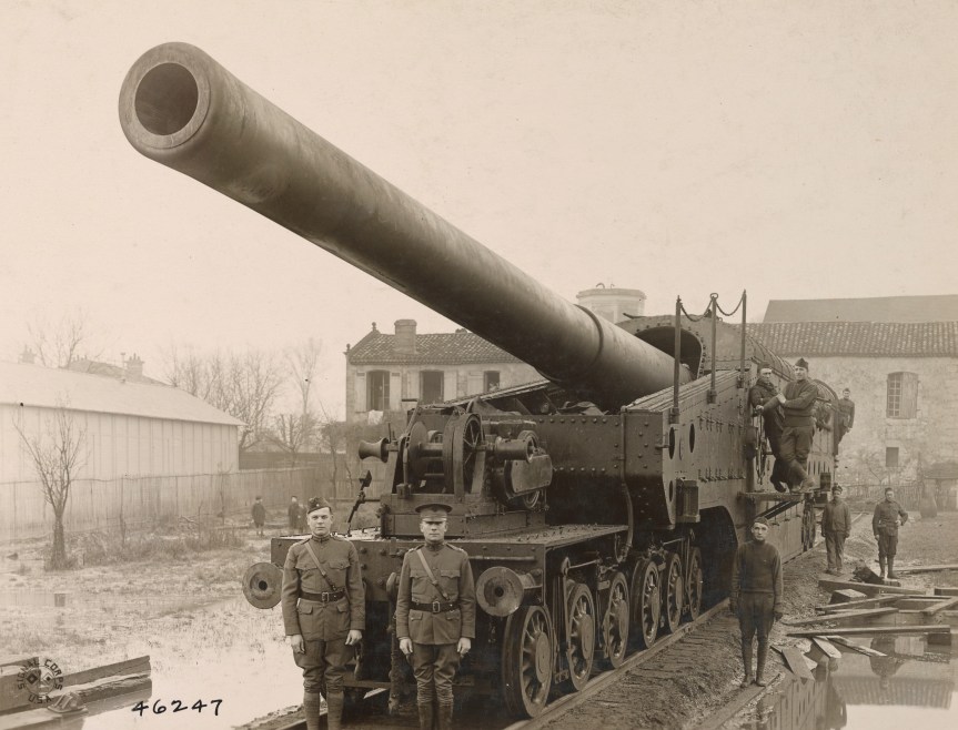
Railway guns emerged during the late 19th century as a way of moving massive, large calibre guns which had a reach far beyond that of field artillery. Before aircraft were able to effectively attack behind enemy lines railways allowed armies to bring huge guns within range and harass their enemies lines of communication and supply.
This footage comes from Ordnance demonstrations at the Aberdeen Proving Ground in the early 1920s.
16in Coastal Gun (US National Archives)
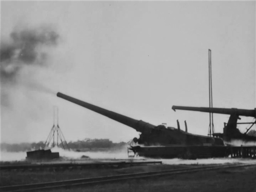
First up we have a US-built copy of the French 305mm Canon de 305 modèle 1893/96 à glissement, which according the original footage notes, was a 10in sliding mount for a gun firing a 150lb projectile. I also found some contemporary images of the gun being built at the US Watertown Arsenal, in Massachusetts, which describes it as the Model 1919. It may be the only example built by the US, Schneider built 8 of these guns for France during the war. When the gun fires we can see the whole gun and carriage recoil back a meter or so. Guns on sliding mounts cant be traversed and have to be aimed with specially laid track.
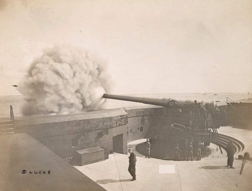
Next we have a 12 inch M1895 gun, mounted on a M1918 railway carriage which was based on the French Batignolles mount, with 360-degree traverse. Originally designed as a coastal defence gun, here’s a photograph taken in 1918 of the gun firing from a disappearing mount.
The M1895 had long been used as a coastal defence gun, and with US entry into the war surplus or unnecessary coastal guns were remounted as railway guns. The railway mounted M1895s had a large recuperator to mitigate the gun’s recoil. 12 were mounted, however, none reached France before the end of the war. We also get a nice shot of the shell hitting its target in the distance.
The 14 inch railway guns were the only big US guns to see action during WW1. Taking spare US Navy 14in naval guns, the 14″/50 caliber Mk 4 gun, which had been mounted in the New Mexico and Tennessee-class battleships, and mounting them in a carriage built by the Baldwin Locomotive Works. Once in position the guns had to have a recoil pit dug out beneath the carriage to allow space for the gun to recoil when it was at high elevation. They had a range of up to 25 miles.
Five Mk1 guns made it to France operating as single gun batteries manned by US Navy Sailors. The guns fired a total of 782 shells during the war, with Battery 4 firing its last shell at 10:57:30 a.m. on 11 November 1918.
Unlike the MkI guns that made it to France in this footage we see the gun without an armoured gun house, with the gunners working the gun in the open.
An M1919 16in Coastal Gun in a Barbette mount (US National Archives)
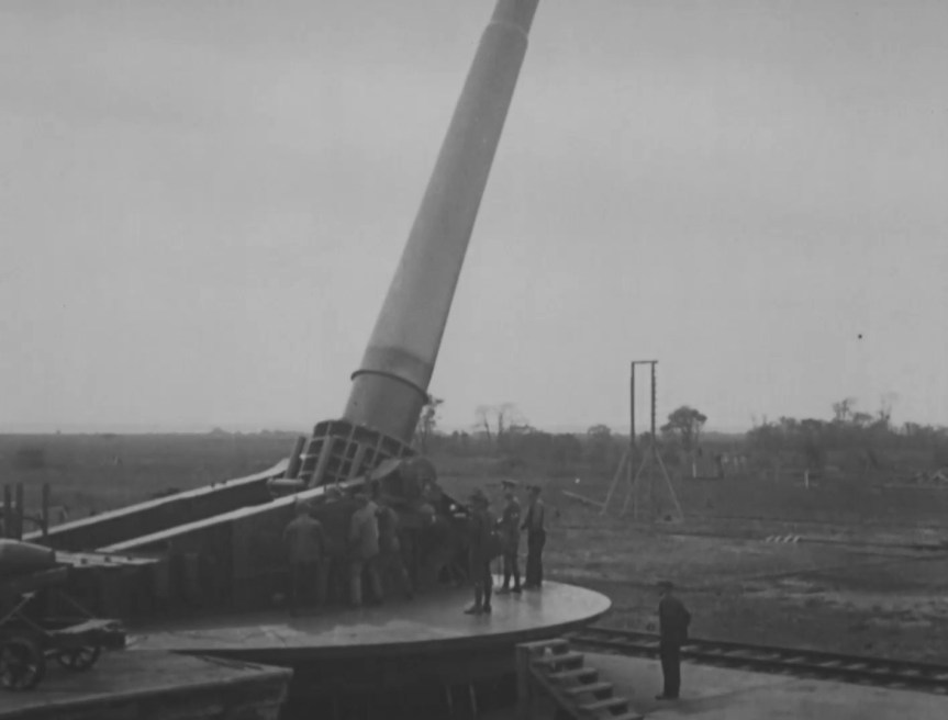
Finally, we have the truly massive 16 inch M1919 coastal gun . Designed for the Army Coast Artillery Corps to defend the US’ major coastal ports the 16-inch gun could throw a 2,340 lb shell up to 28 miles. In this footage we can see the gun mounted on an M1919 barbette carriage which could be elevated up to 65-degrees.
This second piece of footage dates from between 1929 and 1931, with dozens of West Point cadets gathered eagerly to see the gun in action.
Demonstration of Ordnance Materiel at Aberdeen Proving Grounds, 1920-1926 (source)
Railway Artillery: A Report on the Characteristics, Scope of Utility, Etc., of Railway Artillery, Vo.1, H.W. Miller & US Ordnance Dept. (1921) (source)
Railway Artillery: A Report on the Characteristics, Scope of Utility, Etc., of Railway Artillery Vol.2, H.W. Miller & US Ordnance Dept. (1922) (source)
The United States Naval Railway Batteries in France, E. Breck (1922) (source)