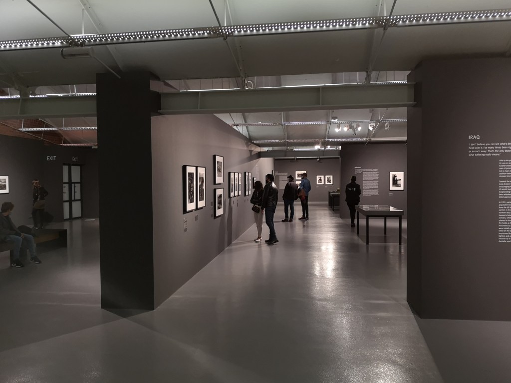
I recently had the pleasure of visiting Tate Liverpool’s Don McCullin exhibition. McCullin is one of my favourite photographers not just for his incredible combat and conflict photography but also for his street photography which focuses on the hardships and lives of people.
Inside the exhibition (Matthew Moss)
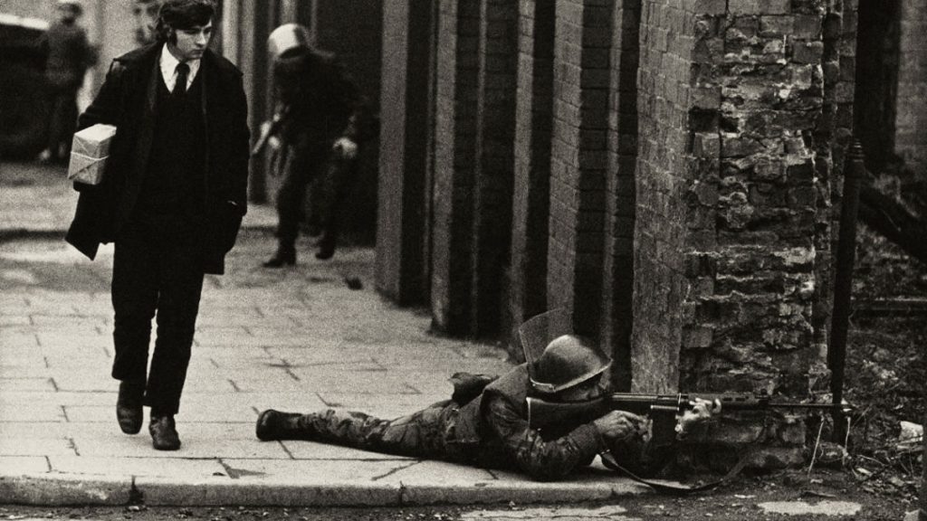
McCullin, now 85, is probably best known for his photographs of conflict, including iconic photographs taken during the Battle of Hue, and his coverage of fighting in Northern Ireland, Crete, Cambodia, Lebanon and throughout Africa. His work covering famine in Ethiopia and the war and refugee crisis in Bangladesh evoke an immense amount of pathos.
Northern Ireland (McCullin)
The Tate’s exhibition is a well deserved retrospective that charts McCullin’s career from its beginnings through to the present – with him most recently travelling to Syria in 2016.
This short video includes some photographs of the exhibition which covered an entire floor of the gallery with each of the conflicts McCullin has photographed covered in chronological sections.
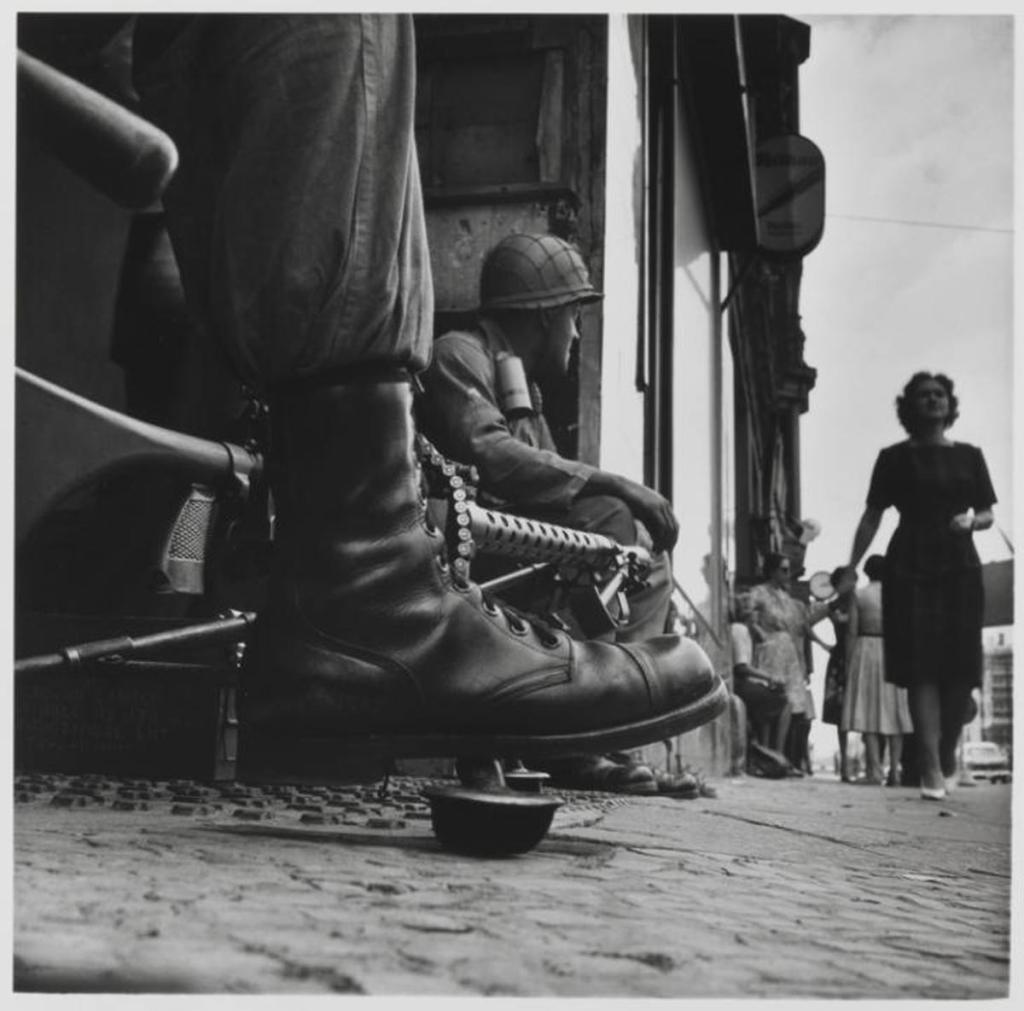
Checkpoint Charlie, with an M1919A6 (McCullin)
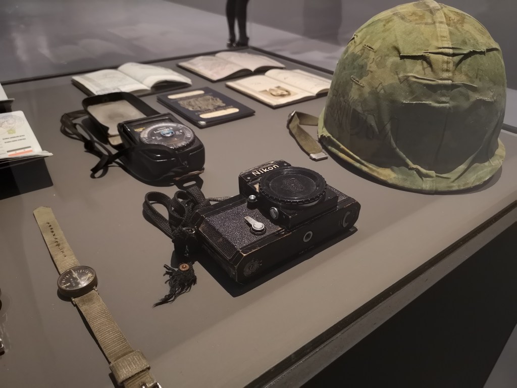
The exhibition is interspersed with collections of magazines which shows how some of his work was originally published by a wide range of magazines and publications. Perhaps the most interesting artefacts on display were a number of McCullin’s personal items including a US Army helmet, a light meter, a watch, passports, a compass and a 35mm Nikon F camera which apparently was struck by a 7.62x39mm round while in Cambodia in 1970.
Some of McCullin’s personal items used on assignment (Matthew Moss)
One thing I did find disappointing as a photographer myself was that the information with each photograph didn’t include what medium – film (35mm or 120) or DSLR, he took the photograph in. McCullin is an immensely skilled photographer with an amazing grasp of composition and technique while being able to capture highly emotive images. As he’s not only a photographer but also an expert photo developer, it would have been nice to have some of this more technical information next to each photograph. Regardless it was an immensely enjoyable exhibition which put into perspective the sheer breadth of McCullin’s work.
One of McCullin’s many photographs of poorer, industrial UK towns & cities (McCullin)Cyprus 1964, (via Tate)One of McCullin’s more recent foggy landscapes (McCullin)
Without doubt McCullin’s life’s work has affected him, seeing so much through the lens of your camera and being largely helpless to help people suffering is something McCullin mentions in a number of interviews and it is a thread in the narrative of the exhibition. McCullin’s most recent work – a series of strikingly moody foggy landscapes is described as being solace from his work documenting conflict and a way of dealing with his experiences.
Find out more about the exhibition here. It runs until the 9th May, 2021.
You can find some of McCullin’s best photographs here.
Development of the XF-87 began at Curtiss-Wright in 1946, it would eventually be intended to be an all-weather interceptor. The Blackhawk was developed from an earlier ground attack, tactical bomber design, the XA-43. The Blackhawk was a response to the initial specification for a jet-powered night fighter, capable of speeds up to 530 mph, issued by the US Army Air Force in August 1945.
A number of companies responded including Bell Aircraft, Consolidated-Vultee, Douglas Aircraft, Northrop, Goodyear and Curtiss-Wright. The US Army Air Force down-selected Northrop’s design – then known as the N-24 and the Curtiss-Wright design- known as the Model 29A.
Curtiss-Wright XF-87 (US Air Force)
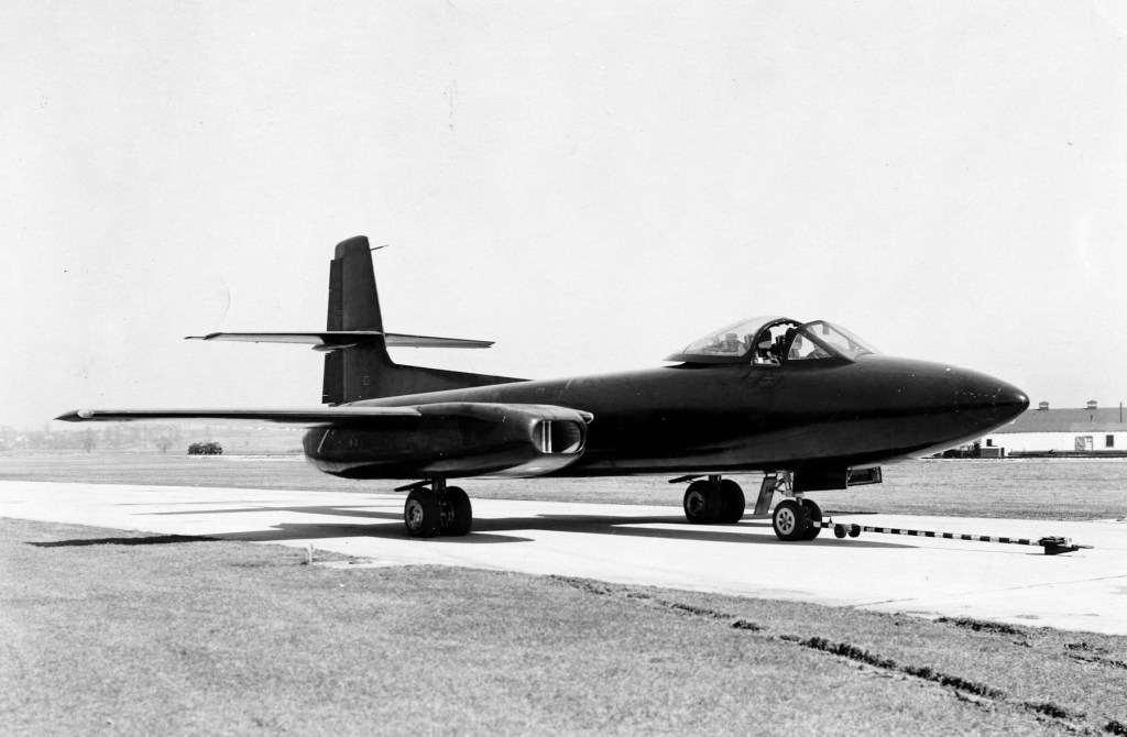
The XP-87 had a two-man crew seated side-by-side and was powered by two pairs of Westinghouse XJ34-WE-7 turbojet engines mounted on the wings. In comparison to the sleeker Northrop design, the Blackhawk was a slightly larger, bulkier and heavier aircraft with a straight wing profile. The XJ34-WE-7 turbojets only provided 12,000 lbf and Curtiss-Wright’s test pilot B. Lee Miller described performance in initial tests as sluggish. The Blackhawk’s armament was to consist of four 20mm cannons mounted in a nose turret.
The US Army Air Force designated the Curtiss-Wright jet the XP-87, while Northrop’s N-24 became the XP-89 and full-scale models of both were ordered.
The Curtis XP-87 (Curtiss-Wright, courtesy of Mark Lane)
In June 1948 the newly formed US Air Force re-designated fighters from P to F and the XP-87 became the XF-87 when prototypes were ordered. The XF-87 made its first flight in March 1948. During subsequent flight evaluations in October 1948, the Northrop XF-89 was found to be faster than the XF-87 and the US Navy’s XF3D (Douglas F3D Skyknight). While the Blackhawk was a capable and generally satisfactory aircraft it was deemed to be underpowered. It also reportedly suffered from buffeting at relatively slow speeds.
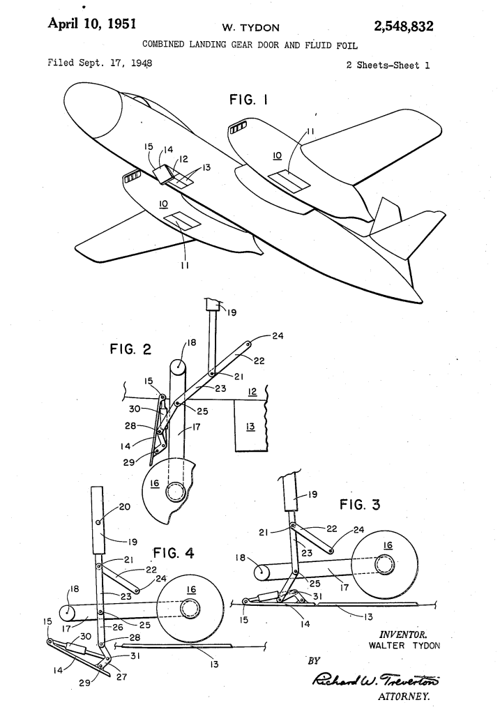
Walter Tydon’s patent for the Blackhawk’s landing gear (US Patent Office)
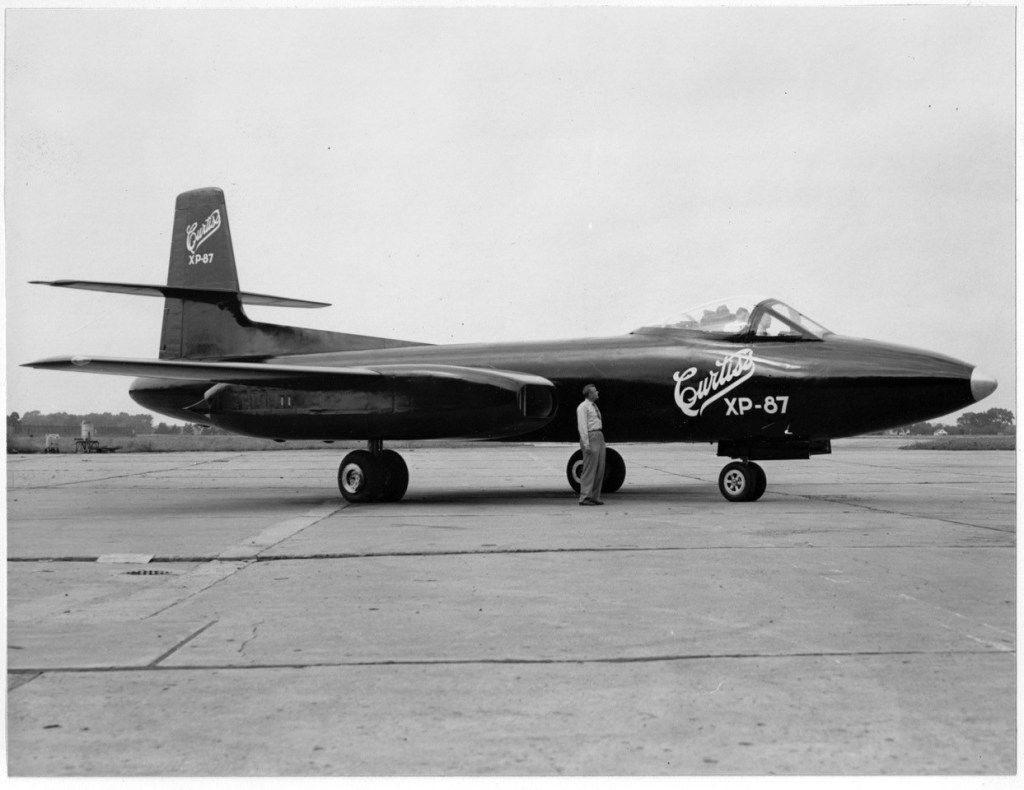
Evaluators disliked the Northrop and reportedly favoured the XF-87, however, one evaluating pilot likened its handling to a medium Bomber. An improved faster and more powerful Blackhawk was planned with J47 engines from General Electric. The fate of a second prototype is unclear and sources conflict. Most sources state that the XF-87 never had its armament fitted, however, photographic evidence clearly shows an aircraft, not with a turret, but with four nose mounted guns. This aircraft may be one of the airworthy prototypes or it could be a full-scale mock up built to show the USAAF during the selection process.
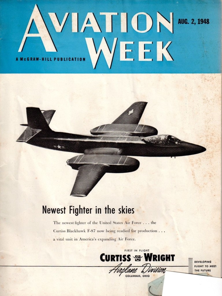
Despite the trials favouring the XF-89, the USAF initially ordered 57 F-87A fighters and 30 RF-87A reconnaissance aircraft from Curtiss-Wright in June 1948. Curtis-Wright and the USAF began a publicity campaign to unveil the new fighter, even appearing on the cover of an August edition of Aviation Week and in numerous other aviation publications, but the orders were abruptly cancelled in October 1948 and the USAF moved forward the development of the Northrop XF-89 instead. Check out our video on the F-89 Scorpion linked above.
The ‘F-87’ Blackhawk on the cover of Aviation Week (courtesy of Mark Lane)
The reason for this reversal of the decision is unclear. Only minor faults had been identified during testing and the more powerful J47 engines would have greatly increased the Blackhawk’s speed. The official reason for the cancellation was reportedly a disagreement on the price of a redesigned wing profile. According to his memoir, Walter Tydon, Curtiss-Wright’s chief engineer at the time, believed that some bad blood between Curtiss-Wright’s management and the then-President Harry S. Truman may have led the F-87 contract to be cancelled. Truman was Senator for Missouri from 1935 to 1945 and during that time Tydon believed he had come into conflict with the Curtiss-Wright’s management, perhaps regarding the company’s factory in St. Louis. Without substantial archival research it is difficult to verify either the official reason or Tydon’s theory.
Another potential reason for the cancellation was raised during the Congressional Hearings regarding the B-36 Program, Congressman Charles B. Deane noted that both Curtiss-Wright and Northrop had been informed that “unless they agreed to merge with Consolidated Vultee, business would be bad for them.” The testimony before the hearing notes that Curtiss-Wright were unenthusiastic about a potential merger and this might have been why the F-87 contract was cancelled. The Secretary of the Air Force denied this, however, stating that the cancellation was the result of “operating difficulties with the experimental model of the F-87, plus increasingly satisfactory operating data on competitive all-weather fighters.”
The XF-87 Blackhawk taking off (courtesy of Mark Lane)
Sadly, the prototype XF-87 Blackhawk’s was reportedly scrapped and photographs and footage of the initial flight testing of the Blackhawk is all we have left. The loss of the interceptor contract to Northrop led to the end of Curtiss-Wright’s aircraft production, with the Blackhawk being their last fighter design.
Special thanks to Mark Lane, the grandson of Walter Tydon, Curtiss-Wright’s chief engineer, for taking the time to discuss the Blackhawk and his grandfather’s role in its design.
In May 1946, George Patchett patented a new curved magazine which would become one of the Sterling’s most recognisable features. It addressed some of the serious shortcomings of the STEN’s magazine.
George Patchett’s machine carbine, Which later that came to be known as the Sterling, had been initially designed to use the standard STEN magazine. This makes complete sense as not only was the STEN’s magazine readily available but it stood to reason that the British Army would prefer to retain the large number of magazines it already had in stores.
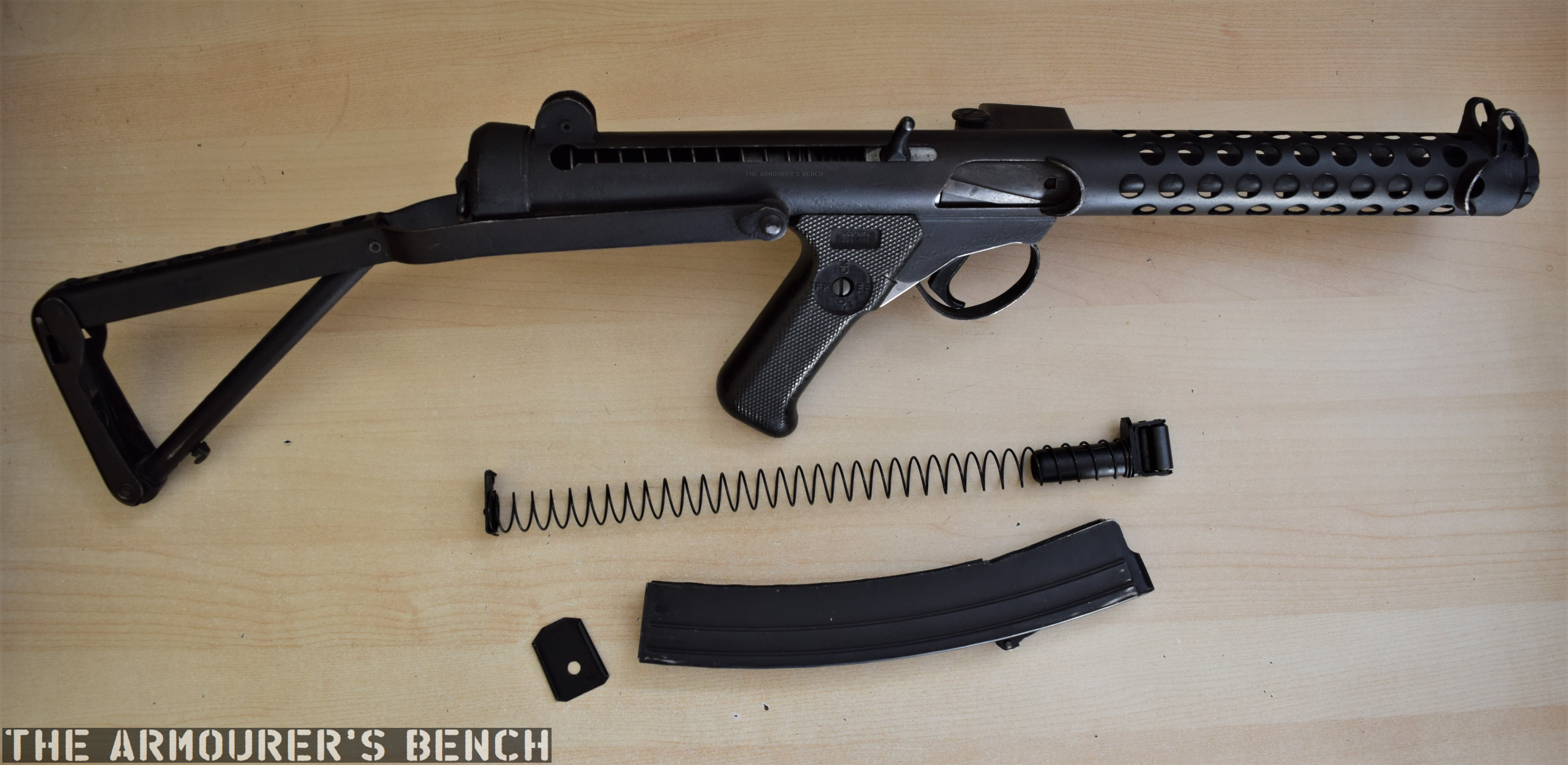
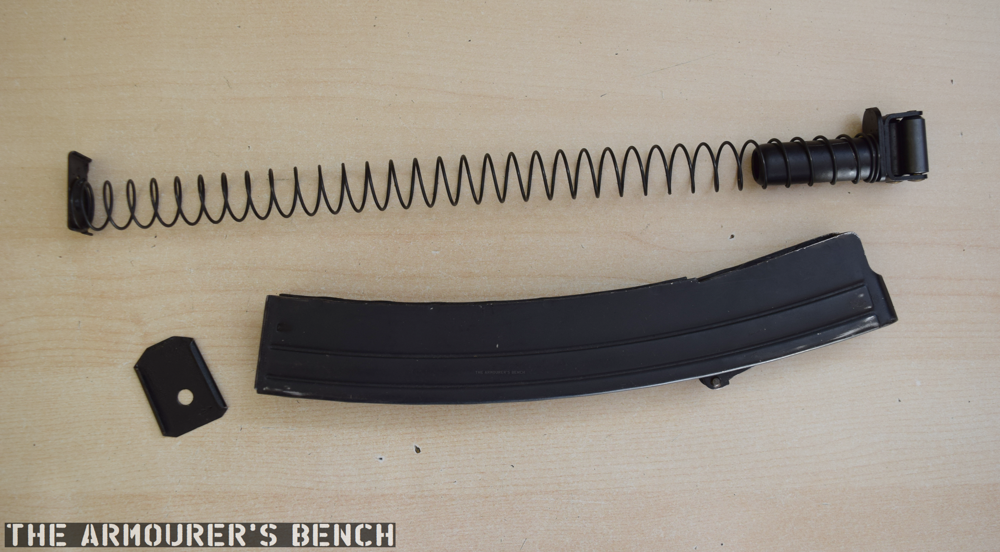
A Sterling L2A3 with a disassembled Sterling commercial-pattern magazine (Matthew Moss)
The STEN’s magazine is, however, the gun’s weakest link. Its a double-stack, single feed 32-round magazine was difficult to load and could feed unreliably when not looked after. The Patchett prototype performed well during initial testing in 1943, but later sand, mud and arctic testing of the Patchett against various other submachine guns highlighted the limitations of the STEN magazine – regardless of the weapon using it.
Patchett’s Original Toolroom prototype (Matthew Moss)
At some point in 1945, Patchett developed a series of new magazines, a 20-round ‘Patrol’ magazine, a 40-round ‘Standard’ magazine and a 60-round ‘Assault’ magazine. By late 1946, these had been superseded by a 35-round magazine designed to fit into the basic pouch of the British Army’s 1944 Pattern web equipment.
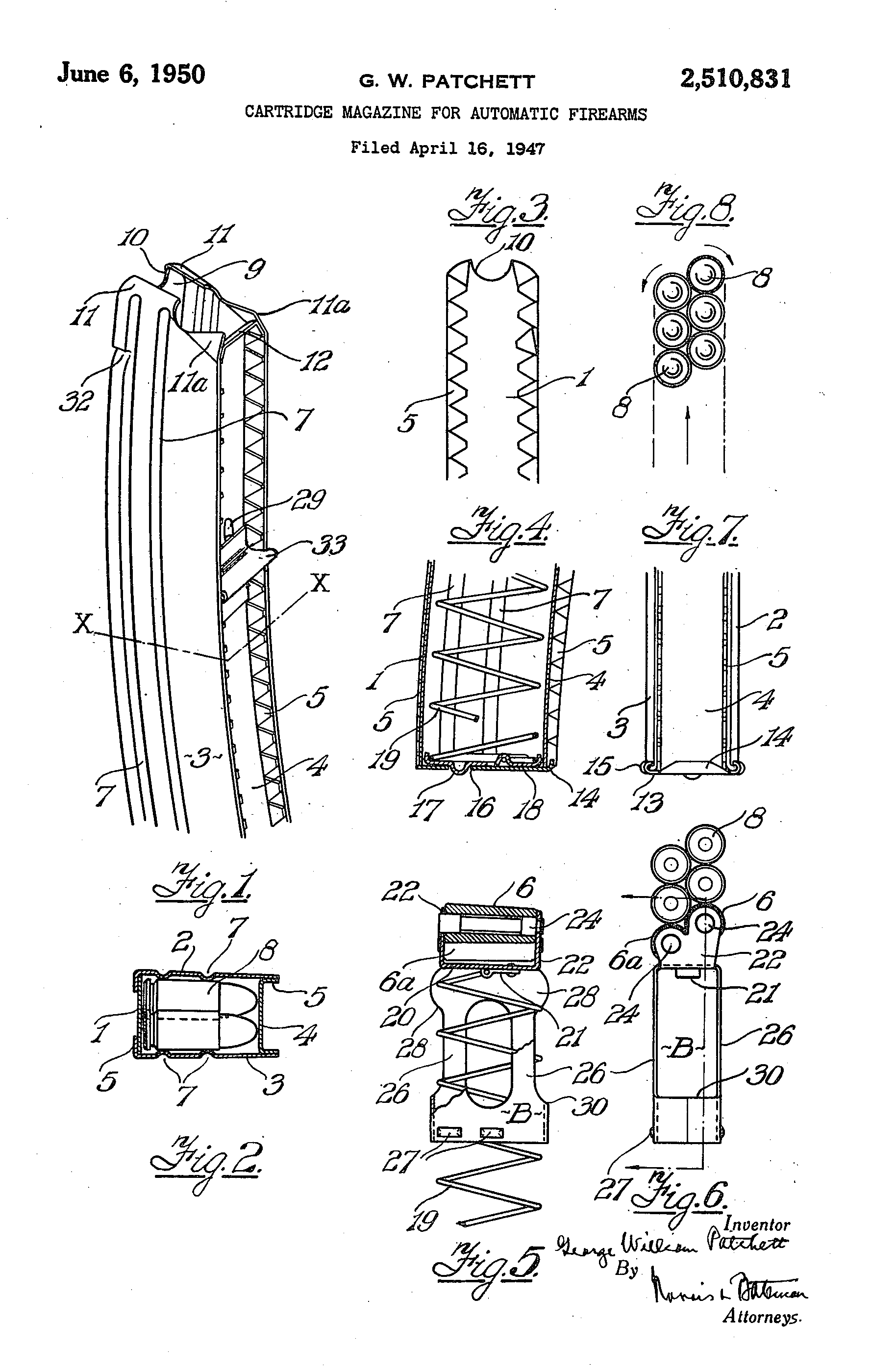
Patchett addressed the STEN magazine’s shortcomings by designing his magazine with a curve which allowed the slightly tapered 9×19mm rounds to feed more reliably. He also replaced the traditional magazine follower with a pair of rollers which minimised friction and allowed dust, grit and dirt to be rolled out of the way improving reliability. Patchett’s magazine was designed so it could be economically stamped from sheet metal and folded and spot welded into shape. It was also simple to disassemble for cleaning and requires no tools for disassembly.
George Patchett’s US patent for his roller magazine follower (US Patent Office)
By 1951 the magazine had been largely perfected but a trials report suggested that the magazine’s feed lips needed to be reinforced. Despite this the Sterling was said to be “better than all other weapons tested.” Following further development and testing the L2A1 Sterling submachine gun was eventually adopted in the summer of 1954. We will cover the development, adoption and service of the Sterling at a later date.
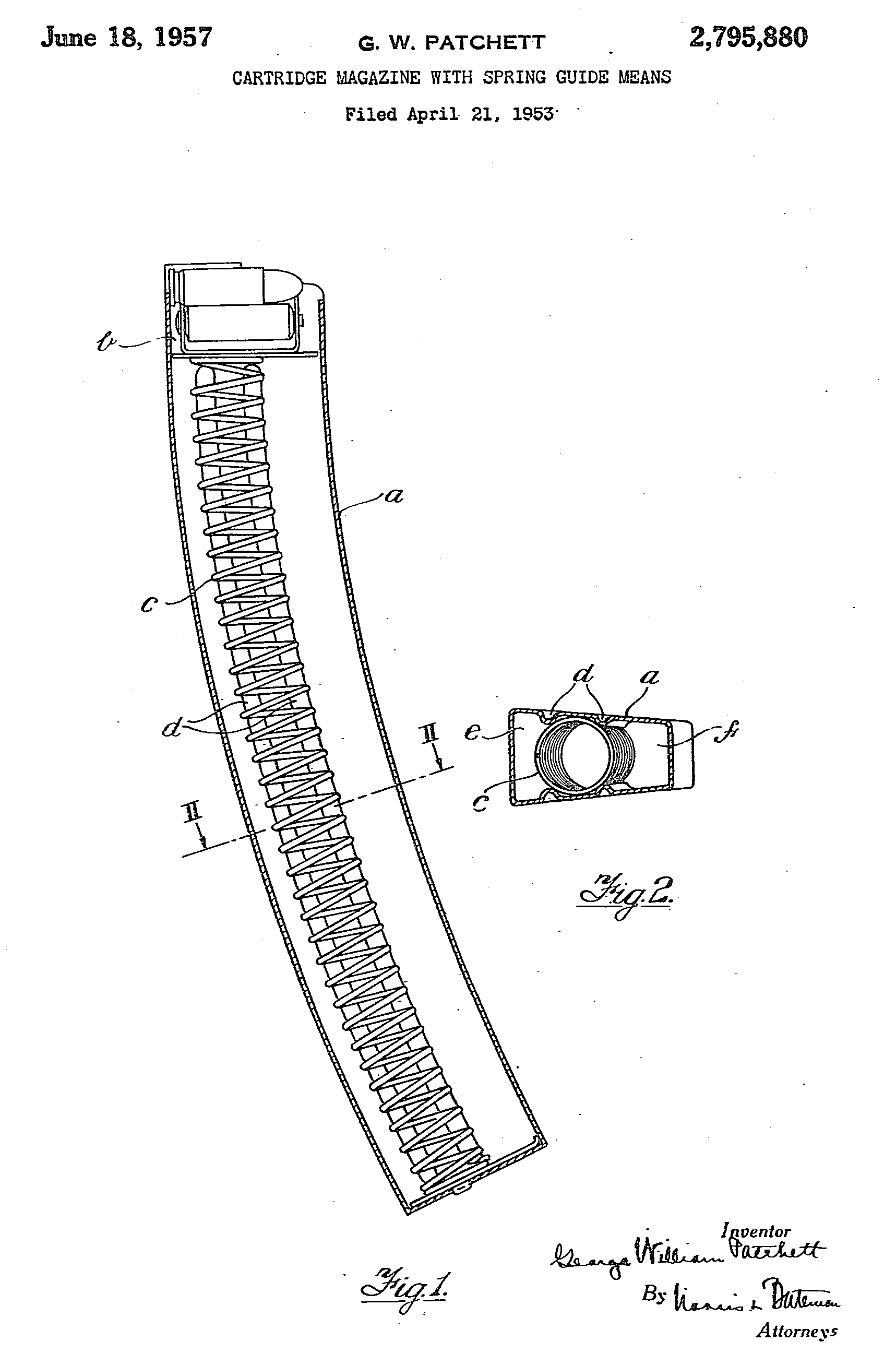
In 1952, Patchett added a pair of strengthening ribs to the inside of the magazine which also further reduced friction on the rollers. He also replaced the oval follower spring with a more efficient circular one with the ribs acting to hold it in place. The final production magazines held 34 rounds and were substantially easier to load than the earlier STEN’s.
Patchett’s US patent for his circular magazine spring held in position by the stamped magazine body (US Patent Office)
The L2A1/MkII, introduced in 1954, was the first Patchett to incorporate an angled magazine housing which improved feeding reliability from the Patchett’s patented curved, double stack, double feed magazine. The Sterling’s magazine housing was angled forward slightly at 82-degrees.
The magazines used by the British military differed from Patchett’s design. The British government, perhaps unwilling to purchase the rights to manufacture Patchett’s design, developed the ‘Magazine, L1A2’. Nearly two million of these were built at Mettoy, Rolls Razor, ROF Fazakerley and the Woolwich Royal Laboratories. The L1A2 magazine was slightly simpler to manufacture but retained Patchett’s roller follower while the magazine’s body was made from two, rather than four, pieces of stamped steel and electrically welded together. The government-designed magazine is 5cm (2 inches) longer than Sterling’s magazines.
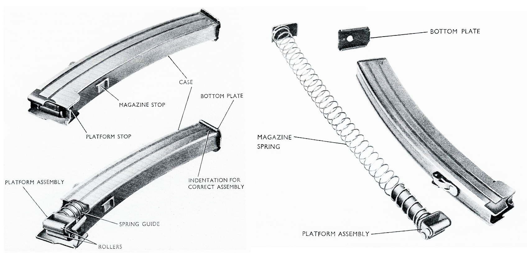
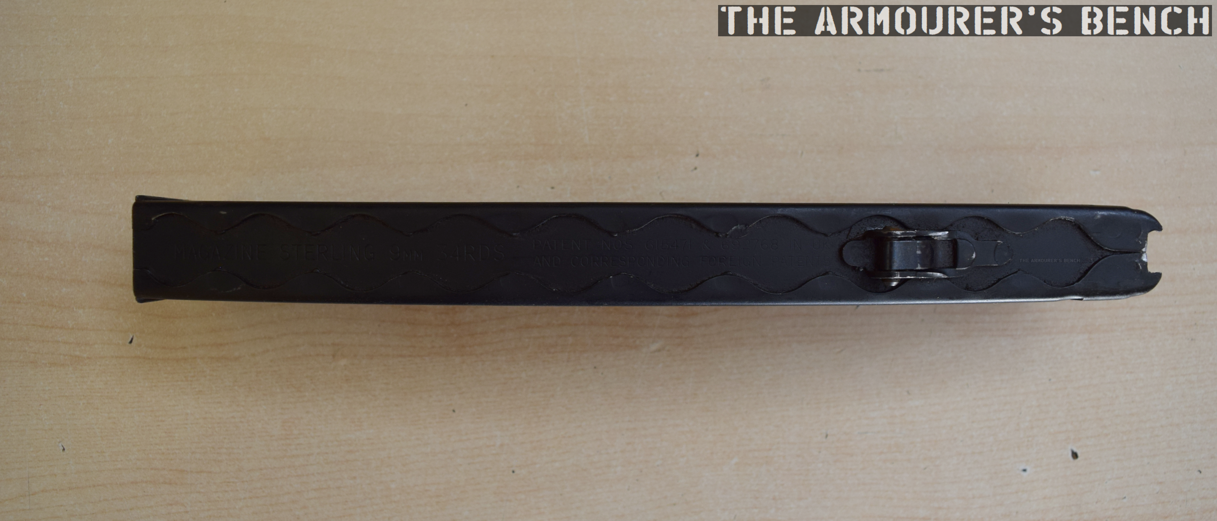
disassembled Sterling commercial-pattern magazine (Matthew Moss)Rear edge of the magazine, with Sterling factory markings (Matthew Moss)
The example magazine seen above and in the accompanying video is Sterling-made and is marked with the company name and patent numbers. We can see the folded sheet metal construction and the overlaps at the rear of the magazine body.
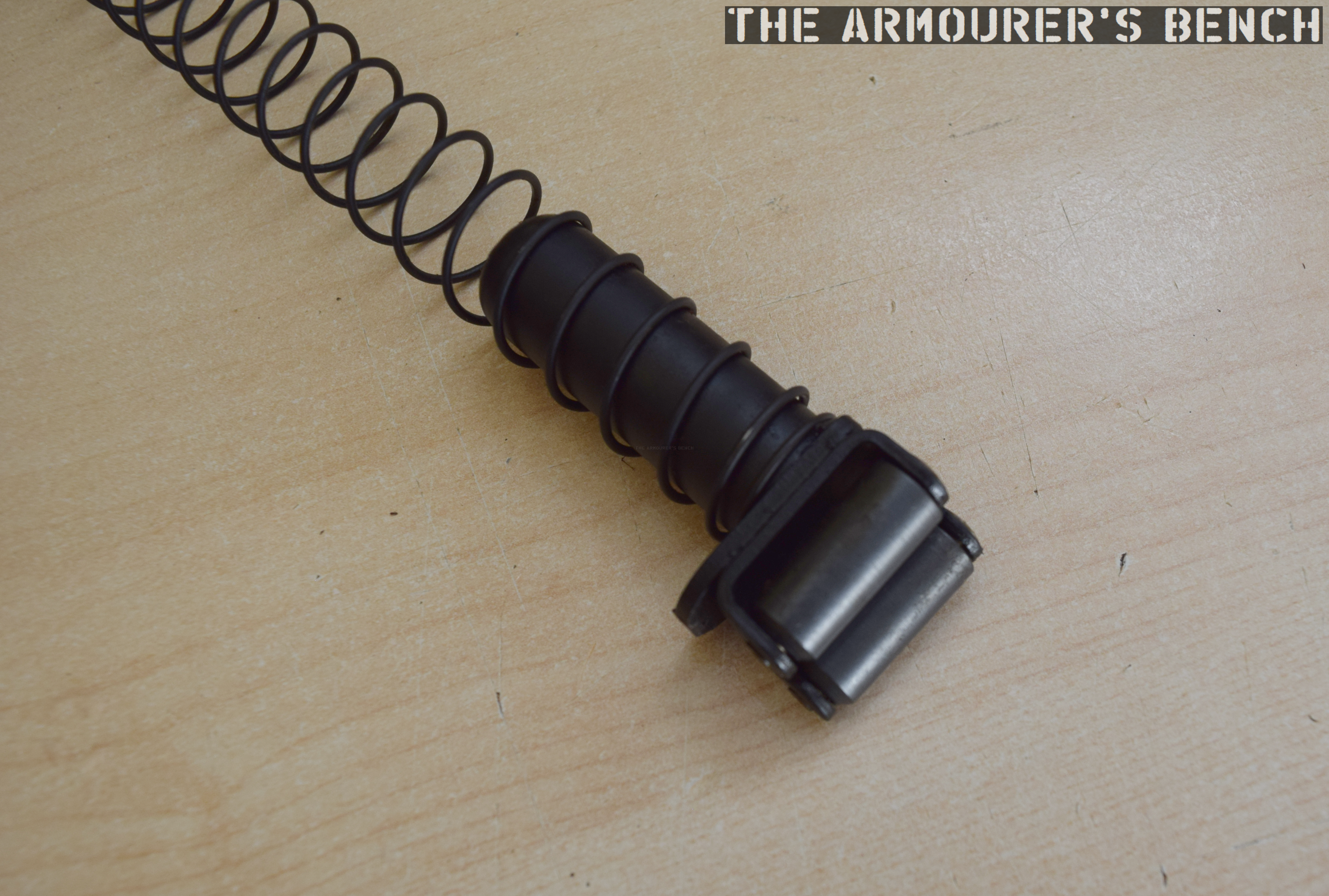
Patchett’s patented-roller follower and circular amazing spring (Matthew Moss)
When Canada adopted the C1, a modified version of the Sterling, they dispensed with Patchett’s roller system and designed their own magazine which held 30, rather than 34 rounds, but could be used in all Sterling-pattern guns.
On the front of the magazine is an over-insertion stop built into the edge of the magazine body, at the rear is another magazine stop with a flat spring which limits rattle and helps properly align the magazine in the breech for optimal feeding.
The need for a lightweight self-propelled anti-tank gun was identified in the late 1940s. The T101 development program took just over 5 years and $2.5 million dollars to develop what became the M56.
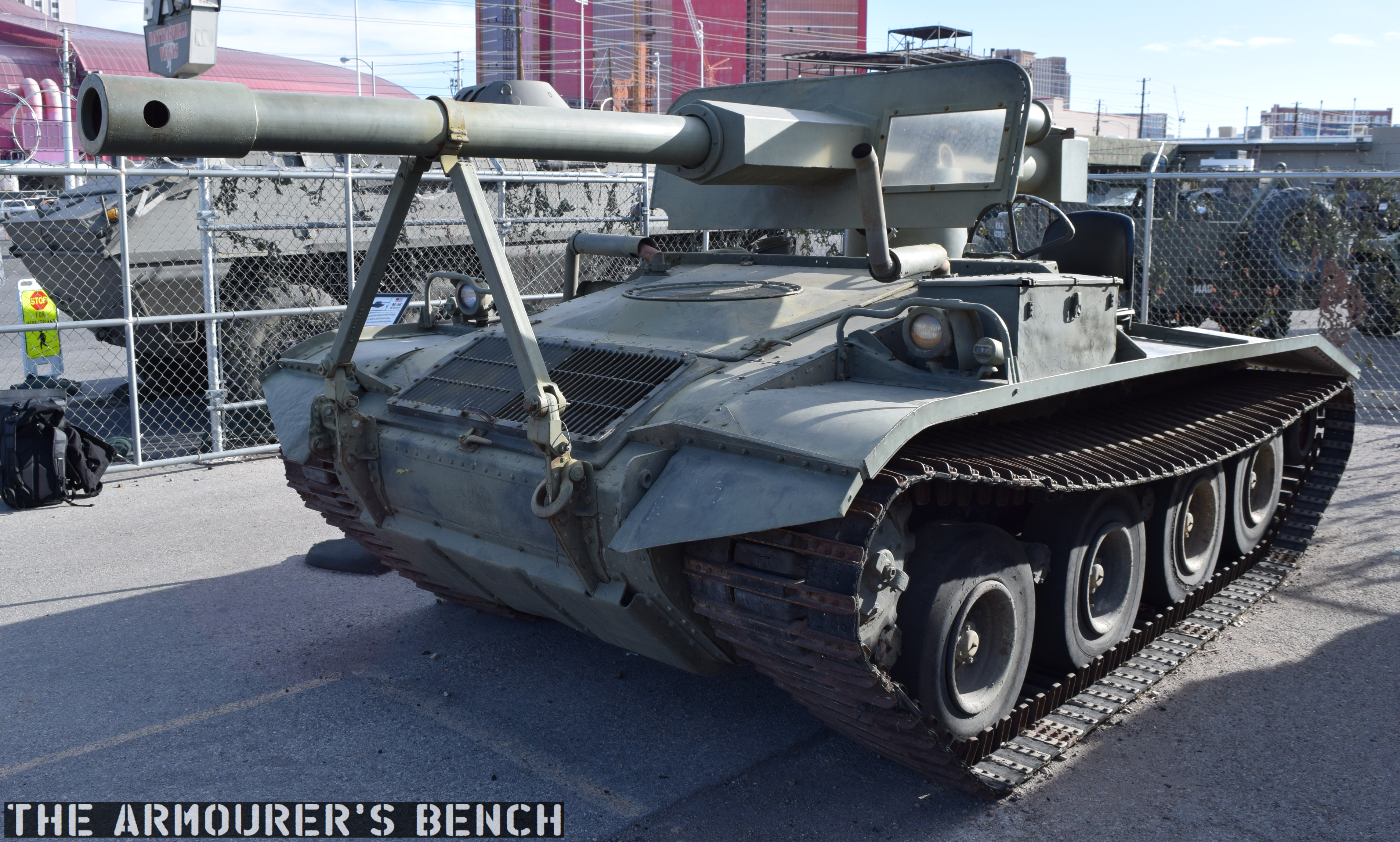
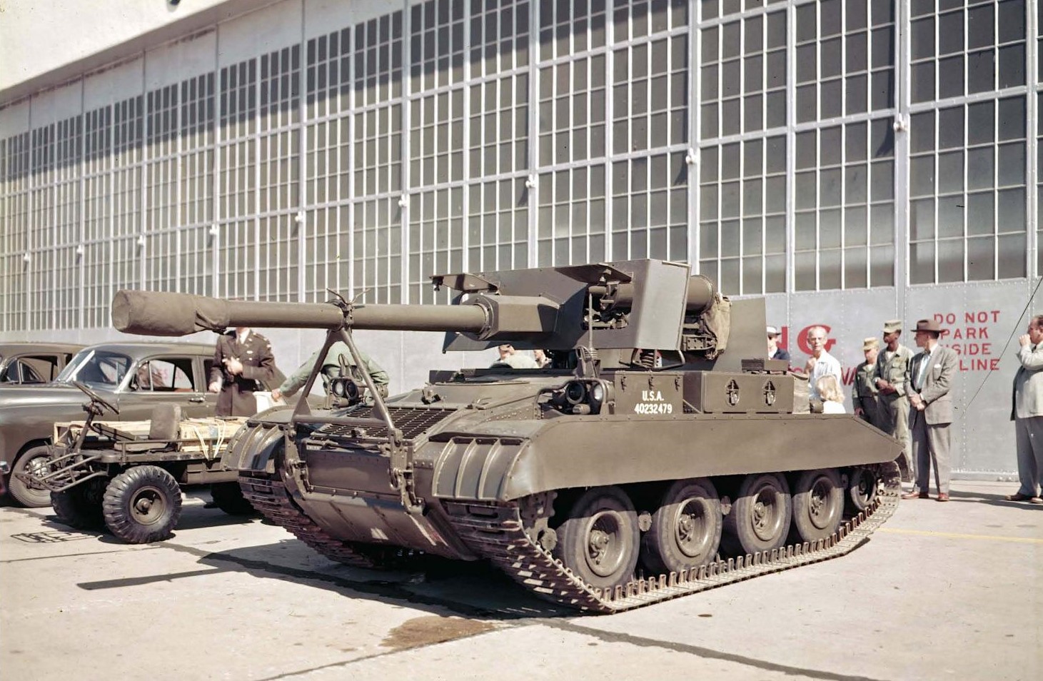
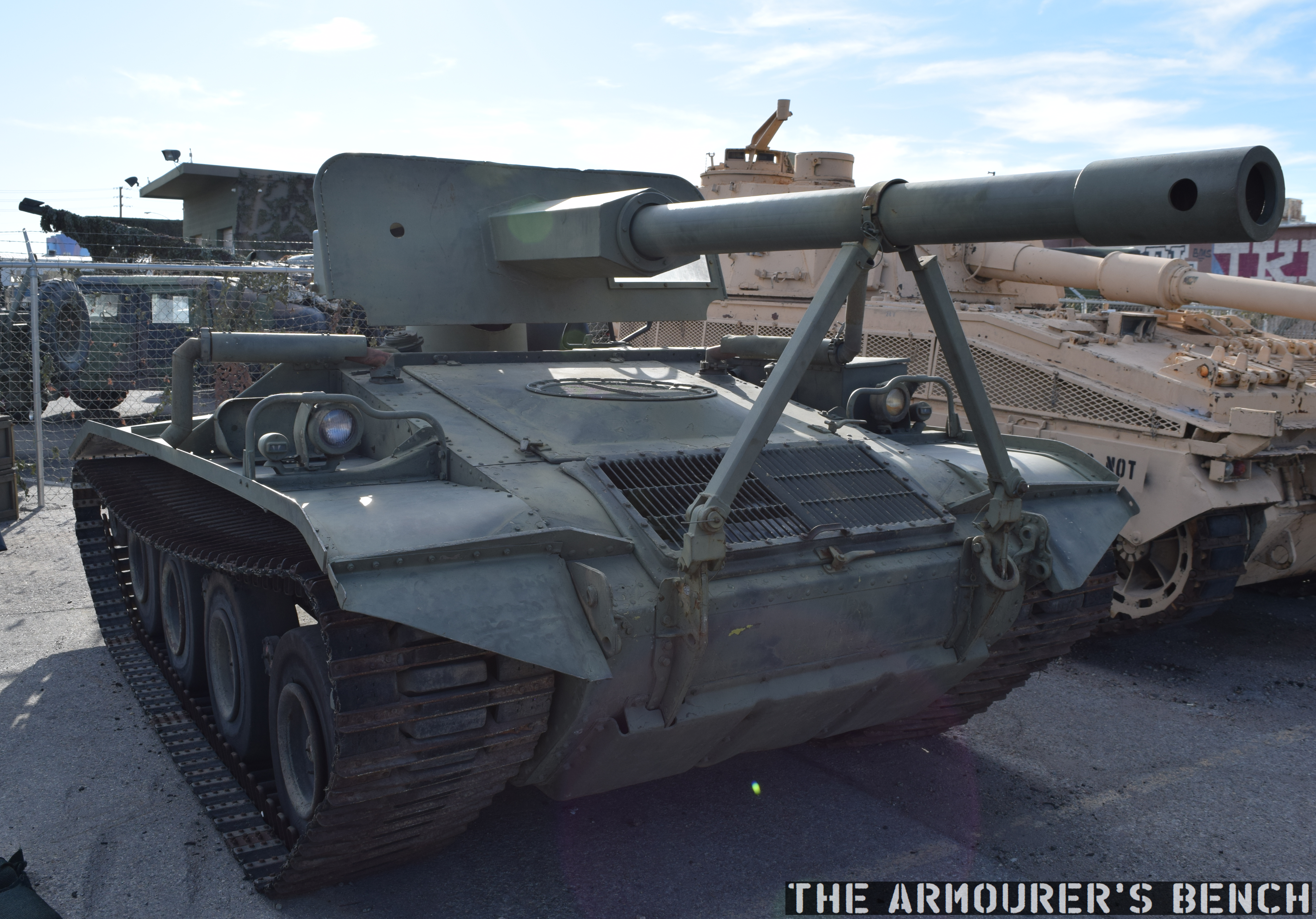
Front, right view of the M56 Scorpion (Matthew Moss)
The M56 was intended to act as an airmobile support weapon for the US Army’s airborne forces that was capable of traversing muddy, marshy, sandy and snowy terrain. Airborne infantry have historically been lightly armed and sometimes struggled against enemy forces equipped with armour. Attempts to level the playing field with glider transported anti-tank guns or even super light tanks could only do so much. Airborne operations during world war two proved light tanks, like the M22 Locust, were out-gunned, under-armoured and largely useless. While light artillery proved effective it lacked mobility and while infantry anti-tank weapons like the Bazooka were extremely useful they were close quarter weapons.
The T101 – Prototype M56 (US National Archive)
In response the US Army decided to abandon one of the points of the classic ‘iron triangle’ of armoured vehicle design all together, sacrificing protection for firepower and mobility. The unarmoured 16,000 lb (7 tonne) vehicle could be dropped from a transport plane to support paratroops and later heliborne air cav units.
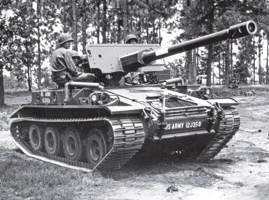
An M56 (US Army)
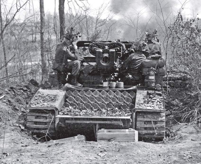
The M56 was developed and manufactured by the Cadillac Motor Car Division of General Motors, a pilot version was completed by 1955. The pilot model, designated the Full-Tracked Self-Proppelled Gun T101 is seen in this photograph from October 1955. When the vehicle finally entered production in 1957 it was largely identical to the T101 except for changes to the location of the radio, the design of the gun’s muzzle device, the hinged flaps on the gun shield were abandoned and the sand skirts were also abandoned. The Scorpion had no secondary armament and no armour. Protection for its 4-man crew amounted to nothing more than a gun shield, which also has a window for the driver.
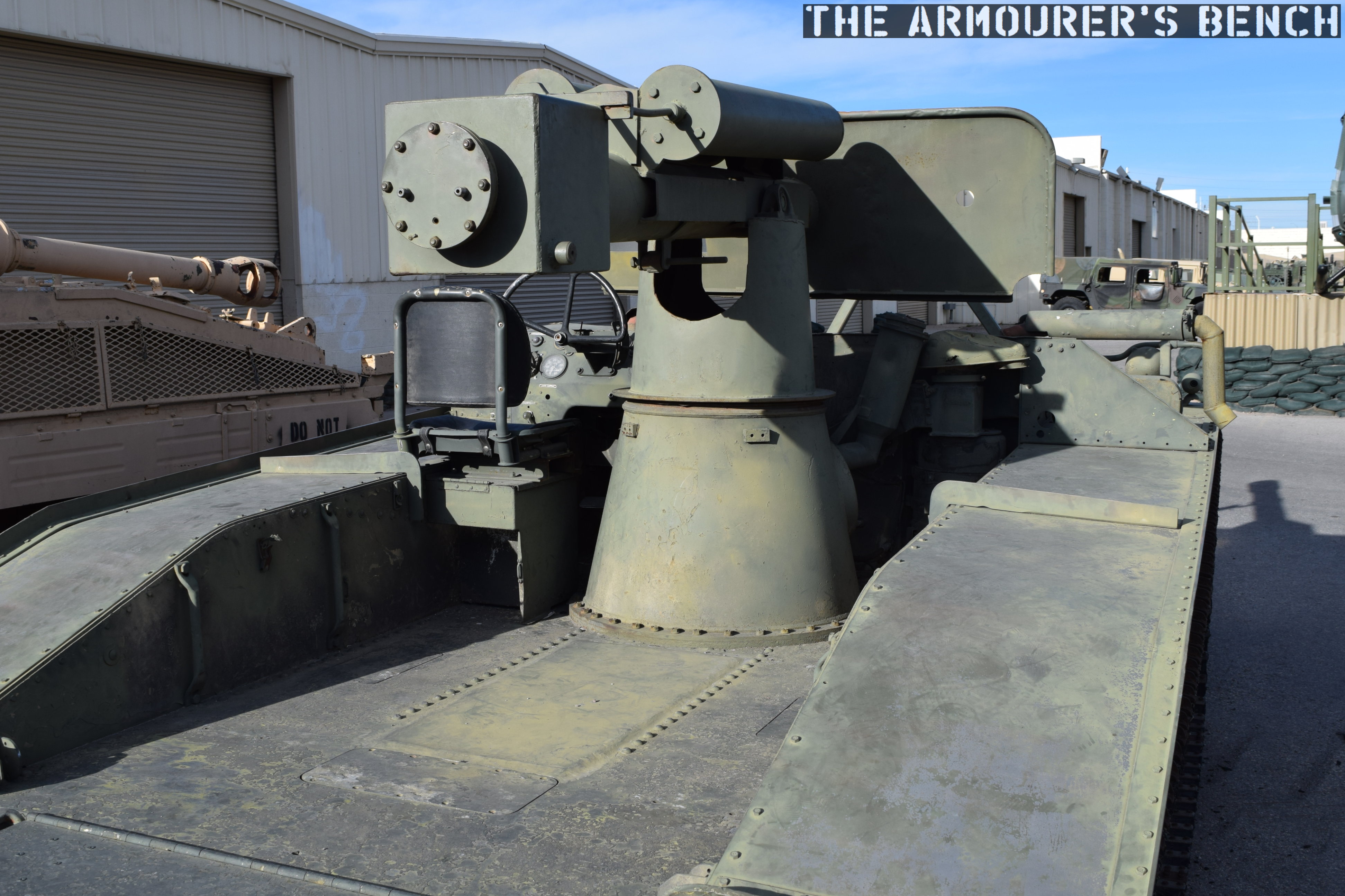
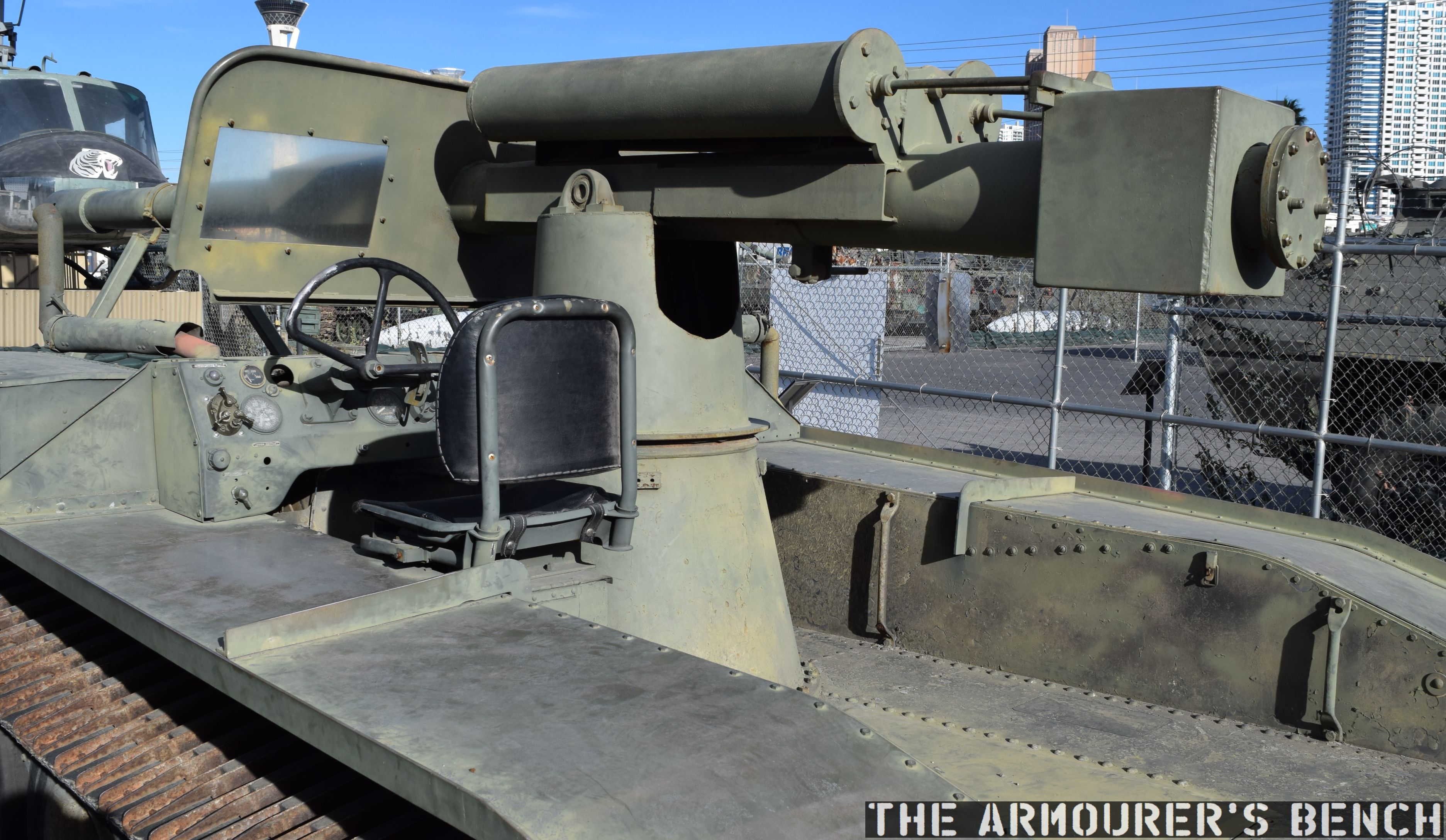
A view of the ‘fighting compartment’ of the M56, the ammunition storage rack is missing(Matthew Moss)
View of the driver’s position (Matthew Moss)
The 90mm M54 high velocity gun was mounted on a pintle in the centre of the vehicle with the driver on the left and the vehicle commander, loader and gunner sat around the gun. The gun could be traversed 30-degrees left and right and had 10-degrees depression and up to 15-degrees elevation. At the rear of the vehicle was an ammunition store that held 29 90mm rounds. The main ammunition used with the M54 would have been the M318 armour piercing round but it could chamber any of the other 90mm ammunition then in US service. Sadly the ammunition store and breech of the gun aren’t present on this example.
An M56 in action, note the ammunition storage racks (US Army)
The gun’s impressive recoil, even with a pair of recuperators, hit the Scorpion and the crew manning it hard, the footage shows just how powerful the recoil was. In this contemporary footage we can see that the front wheel almost bounces off the ground. Note also the semi-automatic action that opens the breech and ejects the spent shell casing after the gun is fired.
The vehicle was powered by an air-cooled petrol engine that produced 200hp. Capable of a maximum speed of just over 28mph.
Front, left view of the M56 (Matthew Moss)
Perhaps its most interesting feature is that it runs on four pneumatic road tyres, rather than metal road wheels, enclosed in a 20in wide track. The track was made up of two bands of rubber and steel cross pieces. There’s a sprocket at the front and an idler at the rear for tensioning the track. This configuration was chosen to reduce weight and it also minimised the ground pressure of the vehicle.
Production of the M56 ended in 1959, after around 325 had been produced. While most of these entered US service, 87 were purchased by Morocco in 1966 while a further 5 were used by the Spanish Marine Corps.
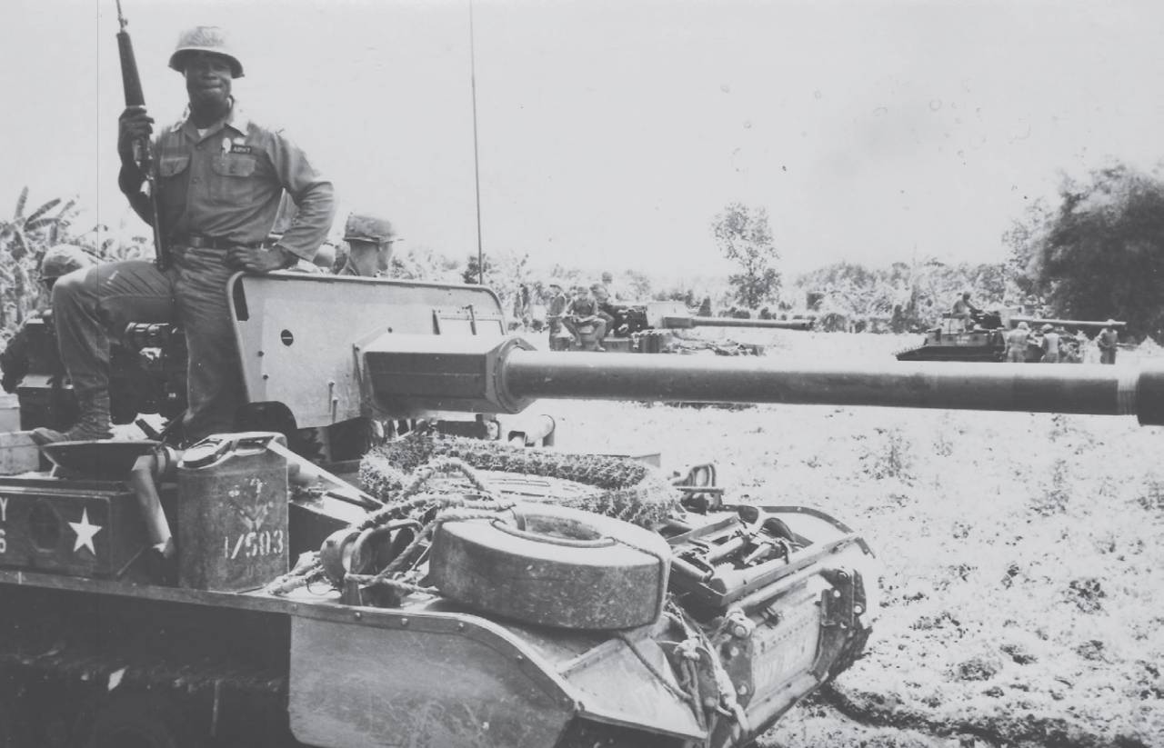
M56s in Vietnam (US Army)
While the M56 was slightly more mobile across country, in reality it wasn’t much better than a standard jeep equipped with a M40 recoilless rifle. Despite the Scorpion’s shortcomings it remained in service into the early 1970s and saw action during the Vietnam War with the 173 Airborne Brigade, which had a company of 16 M56s. In Vietnam the more capable and better protected M551 Sheridan saw wider use and what action the Scorpions did see was largely acting in direct fire support.
Special thanks to Battlefield Vegas for allowing us to film and feature their M56.
The transfer of rifles began in the autumn of 1940, with the training pamphlet ‘The Home Guard .300 Rifle P.17 (American Manufacture)’ published in September by the government. Which began “it now appears that all ‘Home Guards’ will ultimately be equipped with this rifle…”
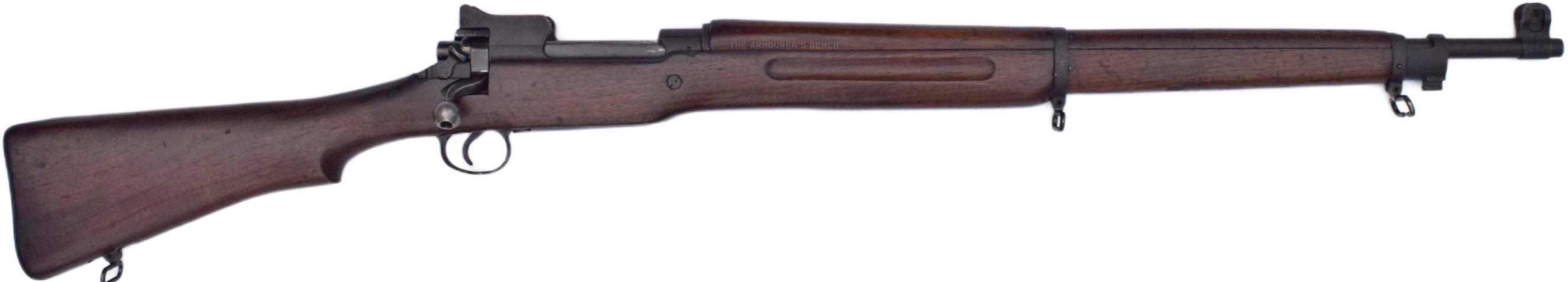
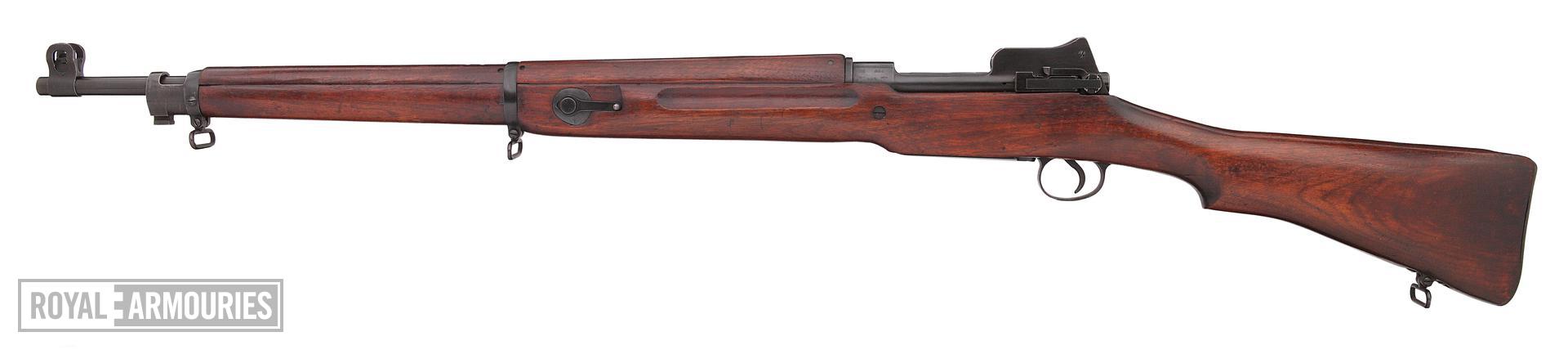
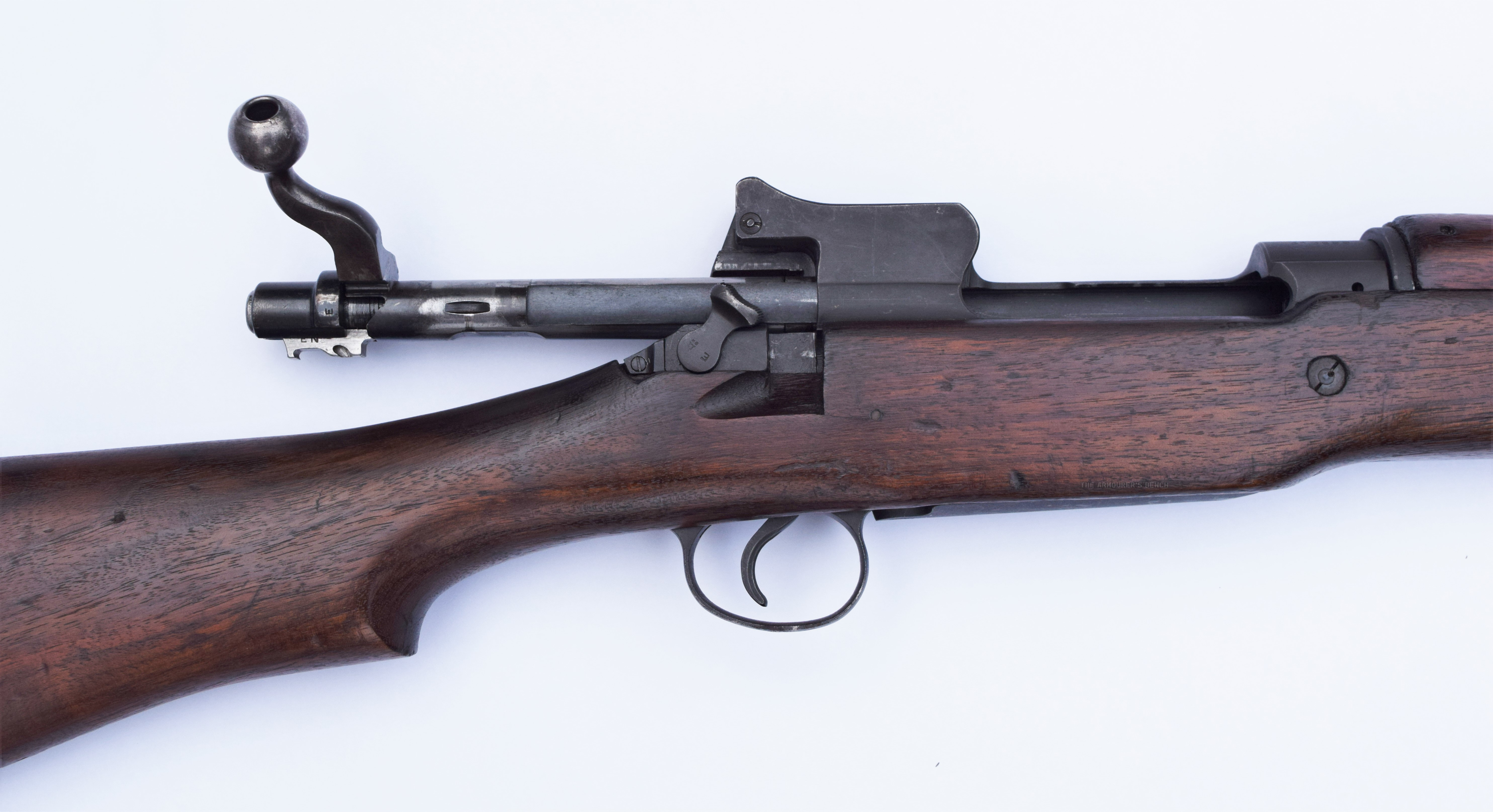
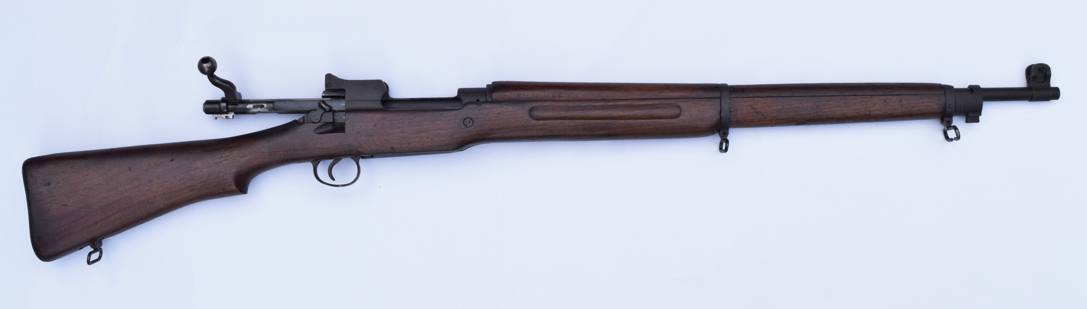
In May 1941, the Home Guard’s .303 rifles began to be withdrawn and reissued to Regular Army units. These rifles were steadily replaced by American M1917s arriving from US stockpiles. This particular rifle was built by Remington in August 1918.
M1917, right side (Matthew Moss)
By the spring of 1942, 80,000 M1917s had arrived, the first of 500,000 that were to be transferred. These would go some way to arming the over 1 million Home Guard members who needed weapons.
The Home Guard were stood up in May 1940, initially known as the Local Defence Volunteers, they were a sort of armed citizen militia made up of men ineligible for regular military service. They were formed into local platoons and companies and were initially poorly armed and equipped. But in time became a well-equipped home defence force.
The M1917 has a somewhat complicated origin. The story began with the British Army’s pre-World War One attempts to replace the SMLE. The Pattern 1913 was developed, based on a modified Mauser action and chambered in a new .276 round. Before the P13 could be fully evaluated and adopted – war were declared – and the British government placed contracts with US manufacturers to produce the Pattern 1914, the P13 adapted to chamber the standard .303 round. Due to a lack of parts interchangeability between the P14s which reached Britain it did not see front line service. In 1917 the US entered the war and found themselves in need of rifles quickly. With the production lines for the P14 already in place at Winchester, Remington and Eddystone the decision was made to produce the P14 chambered in .30-06. This was adopted at the Model 1917.
.303 Pattern 1914 Rifle (Royal Armouries)
The per unit manufacturing cost of the US M1917 rifle in 1917-18 was only $26.00, they almost certainly cost Britain much more to purchase in 1940. Despite the M1917s being more plentiful in 1918, than the M1903 the US Army opted to retain the M1903 as their primary service rifle. As such the rifles sold to Britain had been in storage, often in cosmoline, for two decades and were in good shape.
As the M1917 was chambered in .30-06, or as the British referred to it .300, the rifles were painted with a red band around the wooden forend furniture to prevent the wrong calibre being used. The same measure was taken with the various Browning M1917 medium machine guns and M1918 Automatic Rifles also chambered in the American round. Some rifles also had a .300 stencilled on the butt.
Home Guard riflemen were to be each issued with fifty rounds of .300 ammunition, but in the early stages of the war ammunition was extremely limited. While this hindered familiarisation with the rifle somewhat, it didn’t hinder rifle training completely as many Home Guard units would have practiced with .22 rifles on miniature ranges and with rifles and ammunition provided at Regular Army Ranges. In this clip from some footage of Warwickshire Home Guard men, we see a corporal happily posing with a .22 Martini rifle.
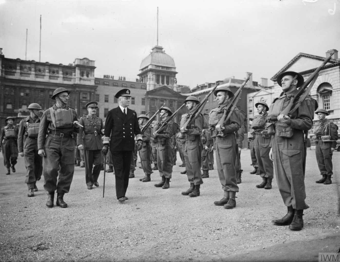
Home Guard on parade with M1917s (Imperial War Museum)
The M1917 is an excellent rifle and the Home Guard were lucky to have them. While those lucky enough to have received an SMLE may have been disappointed when they were given an American rifle in its place many appreciated the rifle. It was certainly better than the smattering of shotguns, civilian rifles, older service rifles and Canadian Ross rifles some units found themselves armed with during the Home Guard’s early days.
One Home Guard Unit In Denbighshire, Wales was initially issued 100 Canadian Ross rifles between 500 men until, in the spring of 1941, they received M1917s. One rifle for every two men.
Clifford Shore, a member of the Home Guard who later became an officer with RAF Regiment, recalled in his post-war memoir that the M1917s:
“were really splendid weapons; I never came across a bad one. In certain quarters they were not popular, but that can be primarily and summarily dismissed with the one word ‘ignorance’. …The higher velocity .300 cartridge gave slightly improved ballistics than the .303 cartridge in the P14, and I should say that the M17 was probably the most accurate rifle I have ever used.”
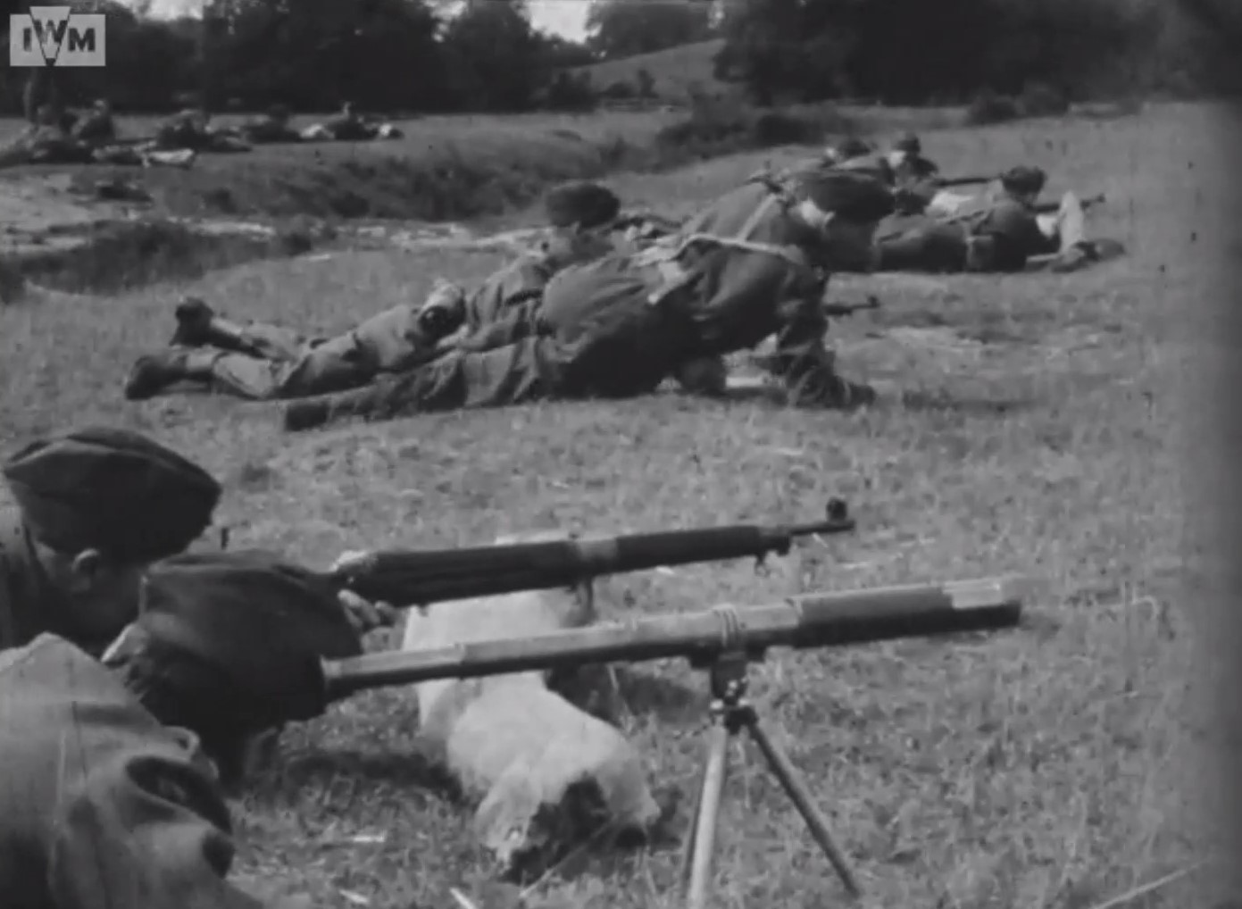
The Warwickshire Home Guard In Action
The video features footage of a Warwickshire Home Guard unit. In it we get a rare glimpse at the men at the range with their M1917s. They’re paired up with spotters and instructors and we also get to see the men in the butts running the targets for the shooters.
Home Guard at the range (Imperial War Museum)
In another piece of footage of the same Home Guard platoon we see them drilling with their rifles. they’re carrying out muscle exercises. The manual for the ‘.300 Rifle P.17’ lays these out.
The 1st practice trained men how to lift the butt of the rifle into their shoulders and how to level the rifle quickly for aiming. The second was to strength the grip of the hands and the 3rd laid down in the manual trained the soldier to hold the rifle steady while aiming building strength to increase stability.
Examining The M1917
The rifle weighs 9.2lbs (or just under 4.2kg) unloaded, it was 46.25in (117cm) long and had a fixed, internal double stack magazine, which because of the lack of a rim on the .30-06, could hold 6 rounds.
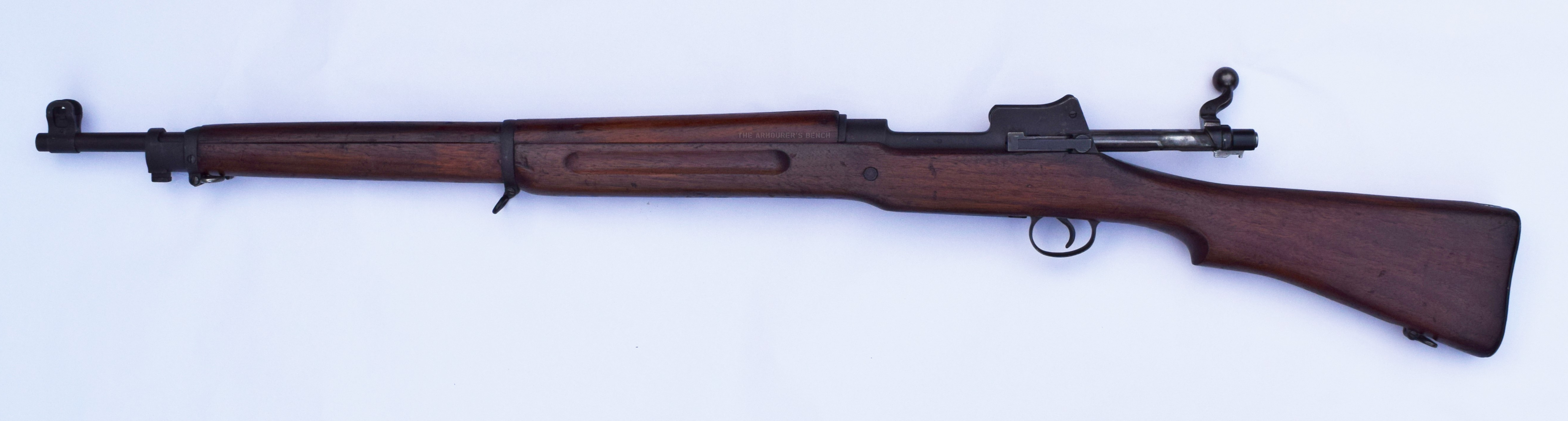
M1917, left side view, action open (Matthew Moss)
The rifle has a Mauser-style bolt release on the right, pull back on that and slide the bolt out. The rifle has an aperture rear sight, zero’d for 200 yards, with a peep also mounted on a ladder giving graduations out to 1,600 yards.
The bolt of course has the dog-leg handle which was carried over from the P14, which in turn emulated the SMLE’s bolt handle position – falling nicely under the hand.
Close up of the M1917’s receiver (Matthew Moss)
Unlike the earlier P14, the 1917 dispensed with the volley sights seen on the British rifles. The action is cock on close and the bolt itself is based on the Mauser 1898’s.
M1917, right side view, action open (Matthew Moss)
This rifle was manufactured by Remington in August 1918. By the end of production Remington alone had produced 545,541 rifles. At peak output almost 10,000 rifles were being produced per day, with the final number built standing at 1,727,449.
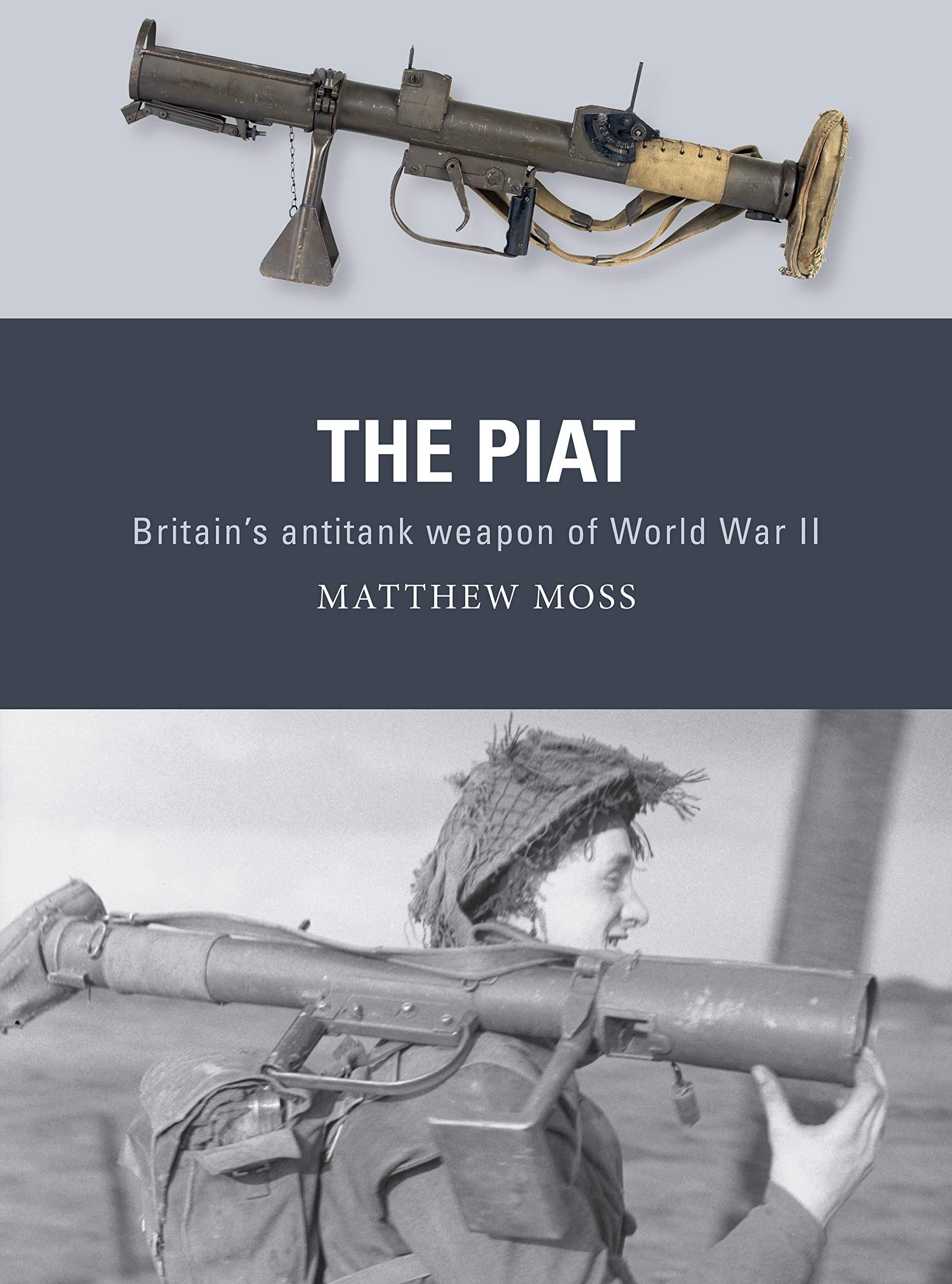
I’m very excited to say that my second book has been published! It looks at the much maligned and much misunderstood PIAT – Projector, Infantry, Anti-Tank.
The book is available from retailers from the 20th August in the UK/Europe and the 22nd September in the US – but you can order a copy from me now regardless of location. I filmed a short video to show you the book and talk a bit about the process of writing it, check that out above.
The PIAT was the British infantry’s primary anti-tank weapon of the second half of the Second World War. Unlike the better known US Bazooka the PIAT wasn’t a rocket launcher – it was a spigot mortar. Throwing a 2.5lb bomb, containing a shaped charge capable of penetrating up to 4 inches of armour. Thrown from the spigot by a propellant charge in the base of the bomb, it used a powerful spring to soak up the weapon’s heavy recoil and power its action.
With a limited range the PIAT’s users had to be incredibly brave. This becomes immediately obvious when we see just how many Victoria Crosses, Military Medals and Distinguished Conduct Medals were awarded to men who used the PIAT in action.
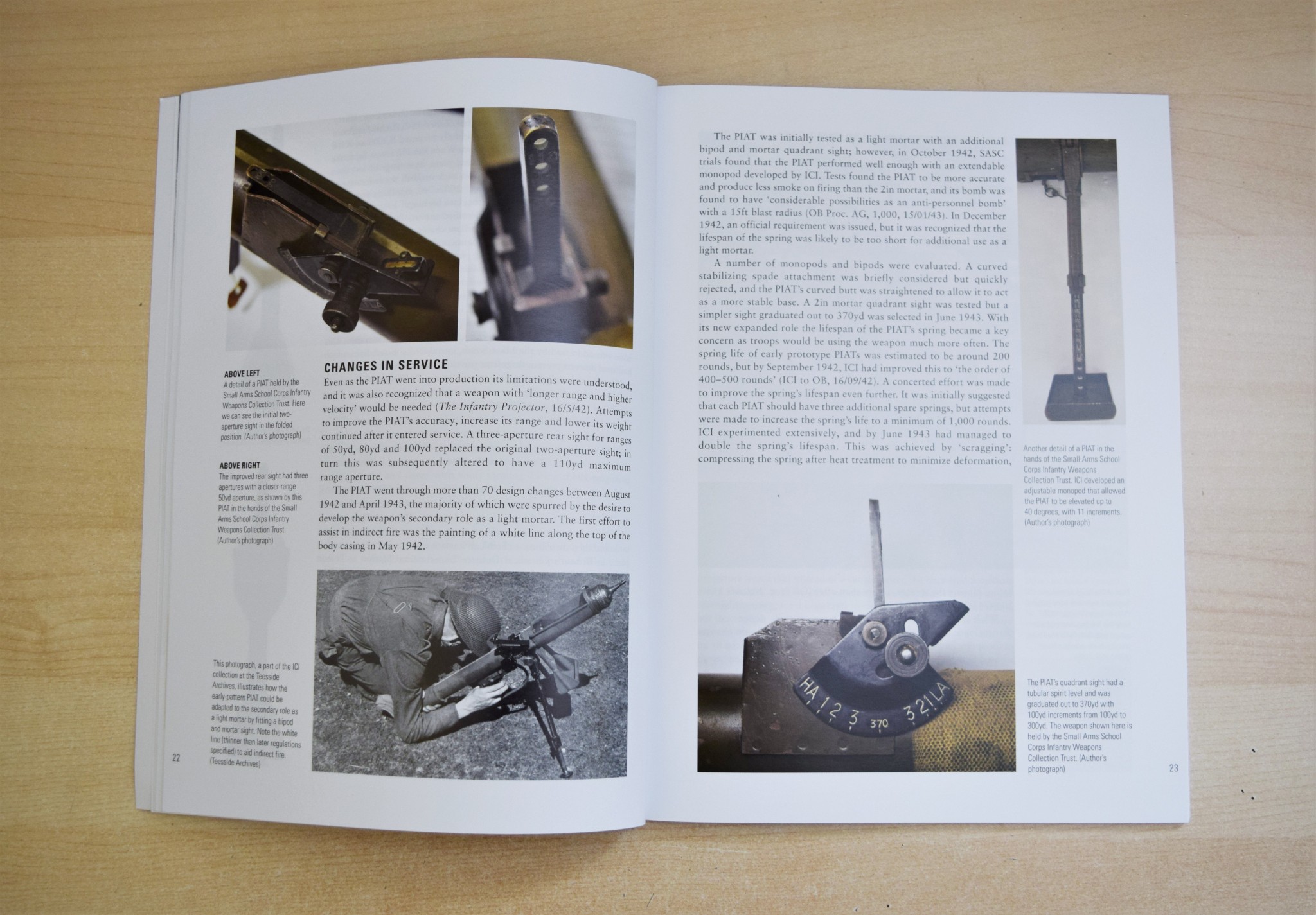
The book includes numerous accounts of how the PIAT was used and how explores just how effective it was. I have spent the past 18 months researching and writing the book and it is great to finally see a copy in person and know it’s now available.
The book includes brand new information dug up from in-depth archival research, never before seen photographs of the PIAT in development and in-service history and it also includes some gorgeous illustrations by Adam Hook and an informative cutaway graphic by Alan Gilliland.
If you order a book directly from me I’ll also include this custom illustrated postcard with a design featuring a PIAT and the famous line from A Bridge Too Far.
It’s immensely exciting to know the book is out in the world for all too enjoy. If you’d like a copy of my new book looking at the PIAT’s design, development and operational history you can order one directly from me here!
Me, bringing up the PIAT…
Thanks for your support and if you pick up a copy of the book I really hope you enjoy it!
During the Second World War Britain’s Special Operations Executive (SOE) developed a whole series of sabotage devices for use behind enemy lines. Using unique archival footage this series of short videos examines some of the weapons developed for use by SOE agents in occupied Europe. In this episode we look at one of the numerous version of the magnetic Limpet Mine developed by SOE and other clandestine organisations.
In this very rare footage we see a Free French Air Force officer, possibly training as a member of the SOE, place a limpet mine on a substantial piece of metal plate.
Free French officer attaching a Limpet to a steel plate (IWM)
The mine seen in the footage is clearly much smaller than the Limpets used against ships. The Limpet mine was developed by Military Intelligence (Research) in late 1939-40. Stuart Macrae and Cecil Vandepeer Clarke developed a mine with enough magnetic strength to attach an explosive charge to the hull of a ship. The initial design seen here was quite large but the design was refined as the war went on with various types and marks. Here’s a Type II limpet, a MkIII and here is a Type 6 MkII.
Limpet MkIII (U.S.N.B.D.)
The idea was that divers or saboteurs in small boats could quietly attach the mines to enemy shipping while at anchor. However, the usefulness of magnetic charges was clear and it appears that smaller versions, like that we see in the footage here, were developed for use against armoured vehicles and other substantial armoured targets.
A demonstration of the Limpet mines and mine carrier (UK National Archives)
It’s unclear from the film what the explosive charge was, how big it was or how it was laid out inside the mine but from the damaged plate displayed at the end of the footage it may have been a ring of plastic explosive held in place by the four magnets. This would blow the characteristic round hold in the plates.
Interestingly, the limpet mine seen in the film is very similar to a Japanese design, the Type 99 anti-tank mine, however, it has a different fuse design and the four magnets are blocky rather than rounded. Whether the Japanese magnetic mine influenced this design developed by SOE is unknown.
Japanese Type 99 anti-tank mine (IWM)
I’ve been unable to find out these mine’s designation, it may not have been given one but it does appear to be fairly well developed. In this photograph we can see that a metal plate carrier has been developed to allow a soldier to carry 4 mines on his back. Perhaps these mines were developed for a specific mission. The magnetic Clam charge, which we have covered in an earlier video, would have done a similar job for smaller task
Sometimes all is not as it seems. That was the case when we examined this Steyr AUG. From the barrel and bipod it appeared to be an AUG in an HBAR or Heavy Barrel configuration but on closer inspection we found that it was in fact a rifle receiver, bolt and bolt assembly and chassis that had been paired with an HBAR barrel assembly.
Vic with the Steyr ‘HBAR’ (Vic Tuff)
Ordinarily, the HBAR could be modified to fire from an open, rather than closed, bolt. This example has the standard AUG progressive trigger for semi and full-auto. It does not have the modified bolt carrier, striker or trigger mechanism.
The HBAR has a 4x optic, rather than the rifle’s 1x, while the HBAR-T can be fitted with an optic like a Kahles ZF69 6×42.
A dedicated ‘LMG’ marked AUG stock and bolt carrier (Vic Tuff)
Adoption of the AUG HBAR does not appear to have been widespread and Steyr don’t currently list it as an option amongst their upgraded AUGs. For more Steyr we have previously examined a Steyr AUG SMG conversion and a Steyr MPi 81. We’ll take an in depth look at the AUG and AUG HBAR in the future.
Overall Length: 35.5in (90cm)
Barrel Length: 24.4in (62cm)
Weight: 8.6lb (3.9kg)
Action: Gas operated, rotating bolt – the HBAR typically fires from an open bolt, but this rifle-based example fires from a closed bolt.
Capacity: 30 or 42-round box magazines
Calibre: 5.56×45mm
Today, were taking a look at a Winchester prototype developed in the mid-1860s, a period when Winchester was seeking to build on the success of the 1860 Henry Rifle and place the company on a firm financial footing. Oliver Winchester had taken control of the New Haven Arms company before the Civil War and while for a time it had been known as the Henry Repeating Arms Company he eventually sought to put his stamp on the company, renaming it Winchester Arms Company in 1866. At the same time he decided to focus the company’s energies on winning military contracts around the world.
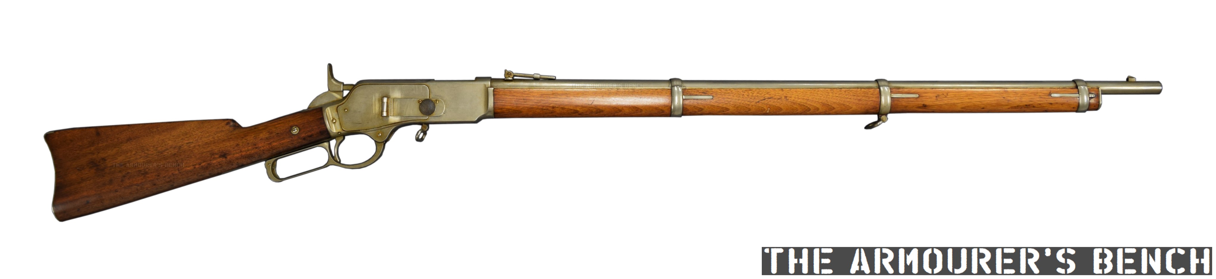
Left & right profiles of King’s prototype musket (Matthew Moss)
This developmental prototype is in the ‘musket’ configuration: with a longer barrel, a bayonet lug and a wooden forend. The prototype represents one of the many developmental steps towards what would become the Model 1866. It has a number of interesting features – a steel, rather than brass, receiver and a hinged loading port developed by Nelson King, Winchester’s superintendent between 1866 and 1875.
The rifle itself was built by Luke Wheelock, Winchester’s model room mechanic and a designer in his own right who would go onto develop his own rifle designs for Winchester.
King’s 1866 patent (US Patent Office)
The rifle is 54.5 inches long, with a 33.75 inch barrel. Believed to have been built in 1866, it is chambered for a .45 calibre rimfire round. King patented his loading port in May 1866. He described how the port worked:
“Through one of the plates S (preferring that one upon the right-hand side) I form an opening, 0, as denoted by broken lines, Fig. 1, and also seen in section, Fig. 7. This opening is formed so as to communicate through the frame directly to the chamber E in the carrier block, as seen in Fig. 3. Through this opening, and while the carrier-block is down and all parts of the arm in a state of rest, insert the cartridges, point first, through the said opening in the plate S into the chamber E the second cartridge pressing the first into the magazine, and so on with each successive cartridge until the magazine is filled, or until the requisite number has been inserted therein, the follower G being pressed up before the entering cartridges. In the rear of the chamber E2 the frame forms a shoulder to prevent the cartridges from being forced out through the opening in the plate S3 is a cover for closing the opening in the plate S3 and is hinged thereto, as seen in Figs. 1 and 7, the hinge being provided with a spring,a1, the tendency of which is to open the cover C. A spring-catch, d, (see Fig. 1,) secures the cover when closed, so that by pressing upon the said catch the cover will fly open. After the requisite number of cartridges have been placed within the magazine, close the cover, as seen in Figs. 1 and 2.”
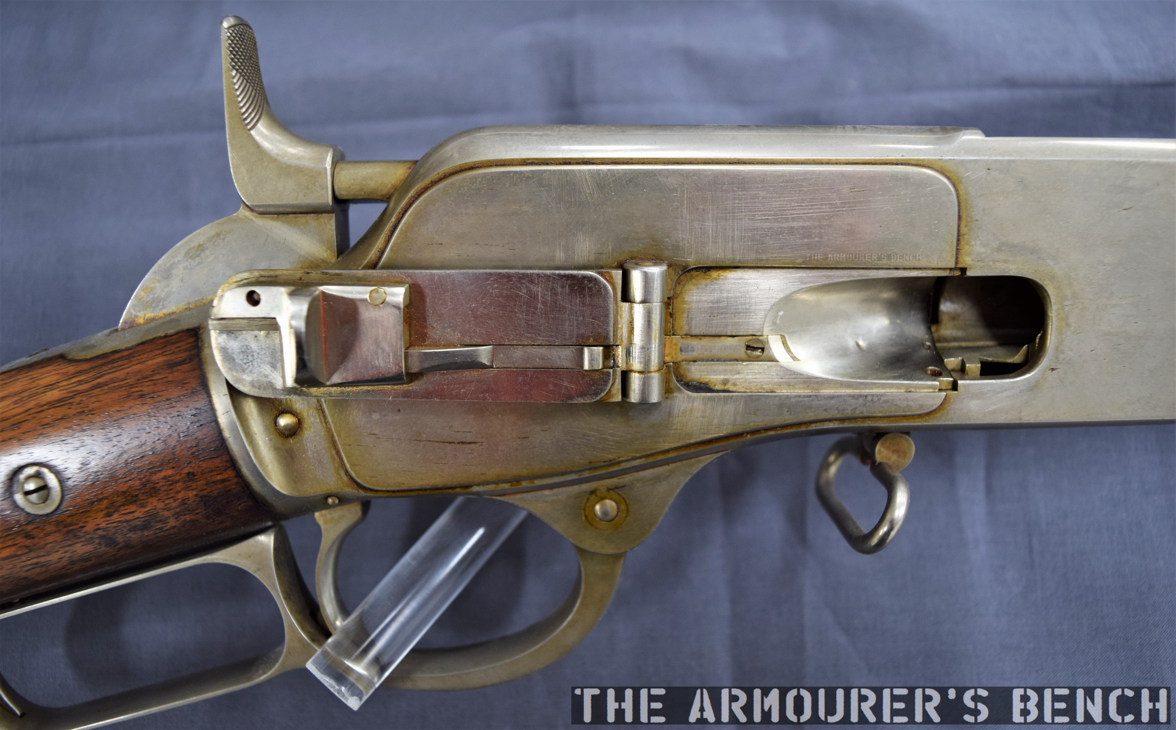
A close up of the hinged loading gate (Matthew Moss)
To paraphrase: ammunition can be loaded through the opening in one of the receiver side plate when the carrier block is down, insert the cartridges through the opening, pressing the first into the magazine and so on until the magazine is filled… a cover for closing the opening is hinged to the receiver side plate. A spring catch secures the cover when closed.
According to Herbert Houze, King developed the covered loading port design in early January 1866, with a design drawing dating to the 14th January, confirming this.
King altered the design of the rifle’s cartridge carrier so that a cartridge could pass through its lower section straight into the magazine when the action was closed. In theory the aperture could be placed on either side of the receiver, in practice is was placed on the right. Prior to this Winchester had experimented with systems where the tube could slide forward (G.W. Briggs US #58937), a port in the base of the receiver (J.D. Smith US #52934) or a sliding forearm covering a loading port at the rear of the magazine tube (O.F. Winchester UK #3284 [19/12/1865]).
A look inside the hinged loading gate (Matthew Moss)
King’s system had the benefit of allowing the rifle to be quickly loaded or topped off without rendering the rifle unusable while loading. Positioning the port in the receiver allowed the magazine tube to be enclosed by a wooden forend.
A cartridge guide was fitted inside the receiver which guided rounds through the cartridge carrier and into the tube magazine. The rounds were prevented from popping out of the magazine, when the carrier was aligned and the cover open, by a shallow shoulder which projected in line with the carrier’s channel to hold cartridges in the tube by their rim.
The musket with its action open, bolt to the rear and loading gate open (Matthew Moss)
The hinged cover is held shut by a spring catch mounted on the rear of the cover. When the knurled section on its front is pressed rearwards the cover pops open. The spring catch is actuated when it tensions against the cover’s hinge as it is closed. On the back of the cover there is also a cartridge stop for when the cover is closed.
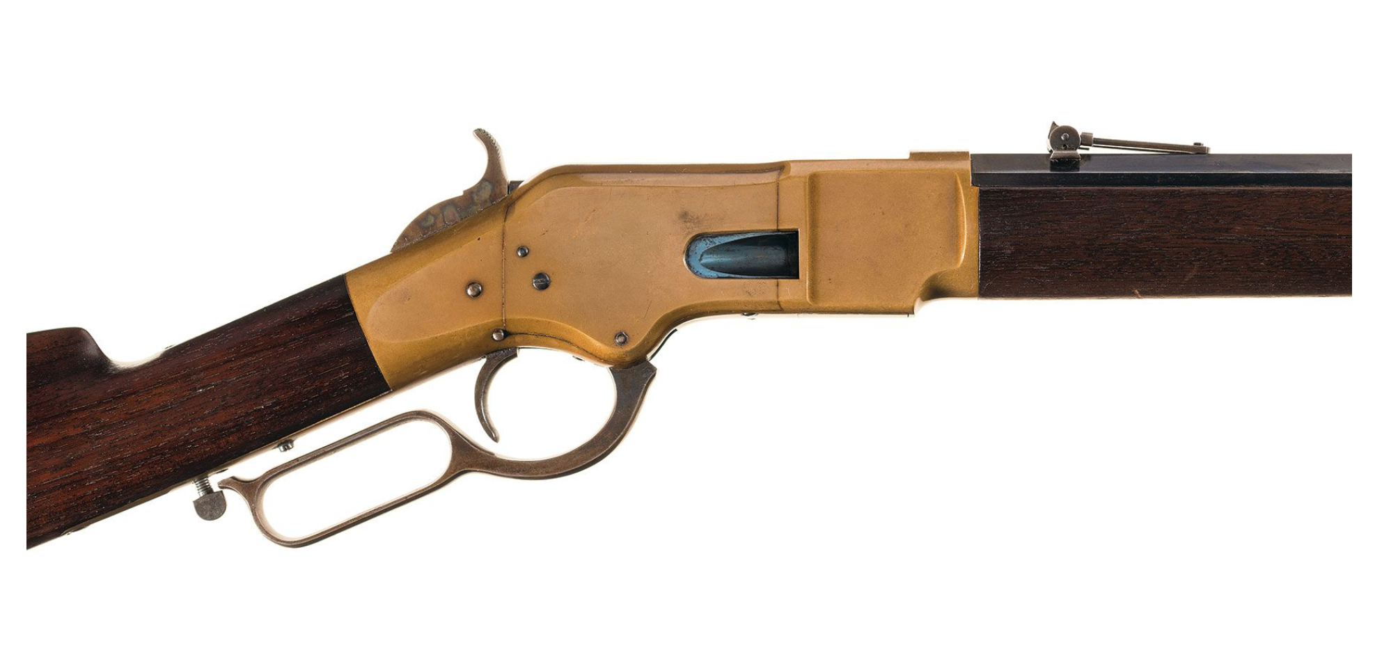
Another small but interesting feature of the prototype is the catch at the rear of the lever loop, this differs from the manually turned catch seen on the Henry and production 1866. This design appears to be a much better safety feature, simply requiring the user’s hand to depress the catch to unlock it from the stock. It also appears to be a much simpler mechanism than that seen in later models like the Model 1895. The trigger also had an extension protruding from its rear which appears to prevent the trigger from being pulled when the lever isn’t full closed. Neither of these features appear in King’s May 1866 patent.
It appears that the idea of the port with a hinged cover was superseded by what we now recognise as the classic Winchester loading gate in the summer of 1866. King’s new system replaced the hinged cover with a piece of stamped spring steel attached to the inside of the receiver side plate by a screw. The spring steel gate could be pushed in, with the nose of a cartridge, to allow rapid loading. The front face of the gate formed a cartridge guide removing the need for the separate machined guide used in King’s earlier iteration of the system.
(Rock Island Auction Company)
King’s revised loading port system required just five, rather than twelve, components: King’s altered cartridge carrier, receiver side plate, spring metal loading gate plate and retaining screws. This simple but elegant design continued to be used for decades on various models of rifle. The company were so pleased with the refinement of the rifle that, according to R.L. Wilson, King was awarded a payment of a $5,000 reward by the company’s board of directors.
Winchester introduced the rifle in 1866, with the first deliveries being made early in 1867, the new rifle was offered in various barrel lengths and patterns including carbine, rifle and ‘musket’. Winchester found some success selling 1866 rifles to the militaries of France and the Ottoman Empire, while many other countries purchased rifles for testing including Britain and Switzerland (whom came close to adopting the Winchester.) The rifles also found success on the civilian market with around 4,500 sold in the first five months.
Right side profile of the rifle showing the hinged loading gate (Matthew Moss)
The Scientific American described the new rifles as “elegant in appearance, compact, strong, and of excellent workmanship. On examination we find its working parts very simple, and not apparently liable to derangement.”
King incrementally developed his loading system before radically simplifying it and this prototype rifle represents an important developmental step in the design of what would become the Model 1866 – one of Winchester’s most important rifles.
Special thanks to the Cody Firearms Museum for allowing us to take a look at this fascinating prototype rifle.
If you enjoyed this article and video please consider supporting our work here. We have some great perks available for Patreon Supporters. You can also support usvia one-time donations here.
Bibliography:
Winchester Repeating Arms Company, H. Houze (1994)
Winchester: An American Legend, R. L. Wilson (1991)
During the Second World War Britain’s Special Operations Executive (SOE) developed a whole series of sabotage devices for use behind enemy lines. Using unique archival footage this series of short videos examines some of the weapons developed for use by SOE agents in occupied Europe. In this episode we look at the component which made so many of them possible – Plastic Explosive. This video contains demonstrations of various uses for the malleable explosive.
The footage, believed to have been filmed in 1940, is part of the Imperial War Museum’s collection, it shows plastic explosive being demonstrated in a number of different applications. It was filmed by Cecil Vandepeer Clarke, a British engineer and sabotage expert who was a member of the Special Operations Executive and worked at a number of weapon research and development centres during the war.
Plastic explosive and its effect (IWM)
The clip features a number of men preparing and shaping plastic explosive charges, adding fuses and detonators. The explosive is then seen being applied to a steel plate in a ring shape, before being detonated. The resulting explosion punches a round hole through the plate. The film also includes demonstrations of what plastic explosive pressed against a tree trunk can do. Once detonated the roughly 1 foot thick trunk is splintered in two. Metal girders are also shown being prepared with a substantial block of explosive being pressed into its seams.
The SOE’s 1944 Descriptive Catalogue of Special Devices and Supplies lists the ‘Standard Charges’ of 1.5lbs or 3lbs of plastic explosive with an integrated central primer available in rectangular blocks inside a rubberised fabric. Of course SOE agents were taught to use as much or as little explosive as was needed for the task and they were taught to be able to improvise in any given situation.
A standard 3lb charge, (SOE’s 1944 Descriptive Catalogue of Special Devices and Supplies)
Given the date of the footage the explosive being used is likely and early form of plastic explosive produced at Woolwich arsenal, possibly PETN or Cyclonite better known as RDX, which would have been mixed with a plasticiser to make the explosive malleable.