The British Army entered the First World War with very few mortars, and certainly none at the battalion level. As the stalemate of trench warfare set in and the effectiveness of enemy mortars became clear it was decided that trench mortars of various sizes would be needed.
Nicknamed ‘plum pudding’ or ‘toffee apple’ mortars after their projectile’s characteristic shape, the 2 inch Medium Mortar or 2 inch Trench Howitzer, was one of Britain’s first effective light trench mortars to be introduced.
Right-side view of the 2in Trench Mortar (Matthew Moss)
Trench mortars were the army’s most forward artillery, right up on the front line. These short range weapons were able to throw large, high explosive projectiles, short distances across No Man’s Land at the enemy trench system opposite. The 2 inch mortar was considered accurate out to 350 yards with a maximum effective range out to just under 600 yards.
Introduced in 1915, the 2 inch mortar was originally crewed by men taken from the battalion it was stationed with, along with some specialists from the Royal Artillery. However, with the introduction of the 3 inch Stokes mortar which was operated by the infantry themselves the 2 inch mortars became the sole responsibility of the Royal Field Artillery.
A young gunner loads a 2in spigot mortar bomb into his mortar (Imperial War Museum)
Mortar positions were often in secondary trenches just behind the infantry’s frontline. This was to help protect the infantry from potential counter-battery fire. The trench mortars were often deployed to sectors to provide counter battery fire against German minenwerfers or in the run up to an offensive or local action. A British Army report on artillery use, drawn up in February 1917, noted that “Owing to their liability to be destroyed by hostile artillery fire it may often be advisable to defer opening fire with these mortars till the last day of bombardment.” The mortars were also tasked with keeping gaps made in the wire clear and with supporting any feint attacks made by infantry during gaps in the bombardment running up to a larger offensive.
Llewelyn Wyn Griffith, a captain with the 15th Royal Welch Fusiliers and later a novelist, recalled in his war memoir:
“At night a trench mortar officer set his guns in a derelict trench about twenty yards behind the line and carried up his ammunition, heavy globes of iron with a little cylindrical projection like a broken handle. In the morning I moved the men from the bays between the trench mortars and their target, to lighten the risk of loss from retaliatory fire.”
Sometimes the width of No Man’s Land required saps to be cut extending out from the frontline so the mortar rounds didn’t fall short. The 50 lb lollipop-like projectile had a maximum effective range of 570 yards (depending on the size of cordite charge used), and could create a crater 5 feet deep and 14 feet wide. The ideal mortar position was a 6 feet wide by 9 feet deep sandbagged pit with the weapon’s heavy wooden bed at the bottom and room for the crew to load the mortar.
A British 2in Mortar position in Mesopotamia, note the ignitor’s breech is open (Imperial War Museum)
Crews could manage to fire approximately once every two minutes. Much slower than the lighter 3 inch Stokes Mortar and but faster than the heavy 9.45 inch Heavy Mortar. The mortar comprising of just its tube, bed, stand and ignition system weighed 320 lbs (145kg), not including the accompanying tools and the Temple silencer system which could be fitted (which weighed 47 lbs or 21 kg alone).
Typically manned by a 5 man mortar crew comprising of an NCO, gunners, and ammunition bearers. To operate the 2 inch mortar a cordite charge was first placed down the tube, the projectile’s shaft was then inserted on top of the charge, the projectile’s fuse was set and checked and a new blank cartridge chambered in the ignition system. The crew then got clear of the weapon and pulled the lanyard to fire the mortar. To reload the crew ran a clearing stick down the tube and then repeated the loading process.
The business end, a view down the length of the mortar (Matthew Moss)
Interestingly, the 2 inch Medium Mortar, like the larger 9.45 inch Heavy Mortar used a cut-down rifle, which screwed into the ‘breech’ end of the mortar tube. This particular mortar has an 1894-dated cut down Lee-Enfield MkI as its ignition system, the cutdown rifle has a wooden insert in its magazine well but it still has its rear volley sight attached. This reusable system replaced the T-tube Friction ignitor, which was in high demand by Britain’s bigger guns. The Lee-Enfield-based system enabled the cordite propellant charges to be ignited by a blank .303 round instead. The rifle’s trigger was pulled with a lanyard from nearby cover. These cutdown ignitor rifle are sometimes confused for Obrez-style Lee-Enfields.
A close up look at the 2in Mortar’s SMLE ignitor (Matthew Moss)
The weight of the cordite charge used dictated the range while a variety of different fuses were used with the projectiles, these screwed into the nose of the bomb. The sphere was about 9.3 inches in diameter with a 2 inch thread for the fuse at its head and a cup for the 22 inch long, 2 inch thick solid cast iron stick or spigot at its base. The sphere was filled with high explosive (Amatol or Ammonal). The high explosive bombs were painted white with a green or pink stripe around their middle.
They were often deployed in batteries of four with three Royal Field Artillery medium mortar batteries attached to each division. The mortars were predominantly tasked with cutting enemy barbed wire and destroying enemy trenches and forward positions, such a machine gun nests.
Men of the Royal Army Ordnance Corps playing cards on a dump of trench mortar ammunition during Battle of the Somme (Imperial War Museum)
Captain Griffith described a battery of 2 inch mortars opening fire on enemy lines:
“A pop, and then a black ball went soaring up, spinning round as it went through the air slowly; more pops and more queer birds against the sky. A stutter of terrific detonations seems to shake the air and the ground, sandbags and bits of timber sailed up slowly and then fell in a calm deliberate way. In the silence that followed the explosions, an angry voice called out in English across No Man’s Land, ‘YOU BLOODY WELSH MURDERERS.’
The 2 inch medium mortar entered service in spring 1915 and remained in use into 1917 with British and Empire troops. It was used on the Western Front and in Mesopotamia. Over 800 were ordered initially with 675,000 bombs, many of the mortars were made in railway and agricultural machinery workshops, allowing larger factories to focus on more complex weapons. The 2 inch mortar was superseded by the larger bore Newton 6 inch mortar later in the war. Some of the remaining 2 inch projectiles were re-purposed as makeshift anti-tank mines, buried in no man’s land in anticipation of possible German tank attacks.
If you enjoyed the video and this article please consider supporting our work here.
In early 1865, in the wake of the Danish-Prussian War which had shown how effective breechloaders could be, Britain’s Board of Ordnance began to explore retrofitting Britain’s muzzle-loading Pattern 1853 Enfield Rifle Muskets with a breech-loading cartridge conversion. Along with this interim solution the Ordnance Department also began the search for a breech-loading rifle designed from the ground up. Dozens of designs were examined from engineers and gunsmiths from across Britain, Europe, and the United States. One of these came from Johann von der Poppenburg, a Birmingham based engineer. Poppenburg’s rifle was tested along with 24 others during the initial phase of testing. The Ordnance Department’s Breech-Loading Rifle Committee were largely unimpressed by the rifles submitted and selected only four to progress, Poppenburg’s design was not included.
An 1866 Benson-Poppenburg Rifle (Matthew Moss)
Poppenburg patented his first breech-loading design in February 1865 (#421) with an American patent following in October (US #50,670). It was this system which was first submitted to the trials, the rifle while described as ‘Poppenburg’s principle’ was made or at least submitted by Messers. Benson and Co., also of Birmingham.
Poppenburg’s patent describes a system that could be loaded with either loose powder and a projectile – with a percussion cap igniting the charge held in the ‘charge-chamber’ or with a paper cartridge which was detonated when pierced by a needle. It was the latter, more modern, option which was chosen for submission to the British trials.
The submitted design used a needle fire action, which ignited a paper cartridge by piercing through the paper and powder to ignite a copper cap in the base of the projectile. Poppenburg patented this cartridge design was on 3rd April 1865 (#932), it lapsed three years later and became void in April 1868. The action was hinged to the right, with a hollow breech chamber swinging out to allow a cartridge to be loaded into it. The estimated unit cost to produce these rifles, for quantities over 5,000 rifles, was £3 each. The needle fire action and hinged breech proved “too complicated, and liable to accident for a military arm” according to the Trials report.
Poppenburg’s needle fire breechloader, patented February 1865 (courtesy of Research Press)
Interestingly, in October 1866 Poppenburg also patented specific system for a breech-loading conversion (#2580). The system used a vertically hinged breech block which locked using a rack and pinion system attached to a lever. It does not appear that this system was tested by the Trials Committee. This action may have been developed following the failure of his more complex action and the adoption of the brass-cased .577 round. This patent lapsed and became void in October 1869.
The October 1866 patent (#2580), appears to be the last patented solely under Poppenburg’s name. Subsequently patents were granted jointly between Poppenburg and John Solomons Benson. This may have been due to the cost of applying for and maintaining patents, which in the 1860s could cost over £45 for three years of protection. Today that’s the equivalent of over £5,000 or nearly $7,000. Both Benson and Poppenburg were based in Birmingham, Britain’s leading centre for small arms manufacturing at the time. In a patent notice, dated 22nd December 1866 (#3382), Benson is listed as a merchant while Poppenburg is described as a mechanical engineer. It may be that Benson provided the financial backing for Poppenburg’s breech-loading system, this was an arrangement that was common at the time.
left and right profiles of the 1866 Benson-Poppenburg (Matthew Moss)
In 1866-7 Benson and Poppenburg submitted a number of rifles for testing in the Prize Competition launched by the War Office to find a new breech-loading rifle. The system submitted was radically different to Poppenburg’s earlier needle fire designs which used hinged breeches. The patent for the new system was granted jointly to Benson and Poppenburg on the 22nd December 1866 (#3382).
Poppenburg’s third breechloading design, co-patented with John Benson, patented December 1866 (courtesy of Research Press)
Benson and Poppenburg’s new rifle had a breech which opened horizontally with a ‘tubular breech-block’ which slid to the rear when a hinged lever was liftedand pulled backwards. To open the breech the rifleman first depressed a small catch on the left side of the breech cover, once depressed the breech block could then be pulled back by the hinged lever. This movement also actuated the rifle’s T-shaped semi-circle extractor allowing the rifleman to remove the spent case. A new cartridge could then be loaded and the breech closed and the striker was then pushed forward with the thumb to cock the weapon. Once the hinged lever was pushed forwards again the breech block moved forward, closing the action, and locked with a pair of lugs cut into the receiver (described as the ‘breech-shoe’ in the patent) and at the rear by the catch.
The Benson-Poppenburg with its breech open, note the t-shaped semi-circular extractor (Matthew Moss)
Depressing the breech release button with the striker cocked will de-cock the action and in theory allow a round to be carried in the chamber. The example pictured in the accompanying photographs may be a slightly more refined version of the rifle submitted as it differs from another rifle, said to be a trials gun, which more closely resembles the December 1866 patent.
Breech Closed (Matthew Moss)
Breech Open (Matthew Moss)
The rifle with its breech closed (left) and open (right)
At least four rifles (with some differences in design between them) were provided for testing, the War Office’s April 1868 Report on Breech Loading Arms found that three of the rifles submitted were shorter than the required length while a fourth was too long – with the maximum overall length allowed being 51 inches. Examples of both full-length rifles, with 32 inch barrels, and carbine models with 23½ inch barrels exist (both of these lengths are significantly shorter than the Snider-Enfield’s barrel length). The trials rifles appear to have been sighted out to 1,100 yards and were chambered in a .577 calibre cartridge (probably the Boxer cartridge selected officially in 1866). At least two probable trials example were also chambered in a .450 cartridge. From a survey of the remaining examples it seems that the serial numbers for the rifles range up to at least 239.
Right side view of the rifle with its breech open, note the breech lever projecting upwards and the breech block and cocking assembly back (Matthew Moss)
The Benson-Poppenburg was unsuccessful during the trials, being rejected from both the Prize Competition and the Breech Action Selection Trials. With the Committee’s report stating that despite the rifles having “several good ideas embodied in their breech action”, they “appear to have been hastily manufactured and the inventions are as yet in an incomplete state”. The specific reasons given for this were that the rifles were of unsatisfactory overall lengths. It seems they were submitted in a rush, in an ‘incomplete state’, with the report also noting that the extractors on two of the rifles submitted destroyed cartridges during extraction, probably ripping the base from the case.
The Committee’s report explained that its rejection from the separate Breech Action Selection Trials was due to issues: “if dirt or sand enters the shoe of this rifle it causes misfires, and even prevents the bolt from entering the aperture in the block.” They also noted that “The working of the breech mechanism is slow.”
The British Army’s extensive trials eventually resulted in the selection of Jacob Snider’s system, adopted in April 1866 to convert existing Pattern 1853s and the selection of Friedrich von Martini’s action and Alexander Henry’s barrel, which when combined as the Martini-Henry was formerly adopted in March 1871.
Addendum:
Mathieu Willemsen, curator of the Netherlands’ Military Museum, was kind enough to share some information about The Dutch Army’s trials with the Poppenburg in 1868. The Dutch trialled a version similar to that tested by the British but chambered in 11x42mmR. The rifle’s action has a more angled external appearance than the example we have examined but works along the same principle.
1868 Benson-Poppenburg trials rifle, note the longer breech lever (courtesy of Mathieu Willemsen)
The rifle was found to be rapid firing but suffered from some issues with fouling and failed a pressure test. Later testing with a smaller calibre round was also carried out but the rifle was not adopted. We hope to have a chance in the future to examine a Dutch trials rifle for comparison.
If you enjoyed the video and this article please consider supporting our work here.
Bibliography:
Treatise on the British Military Martini, I. Skennerton, (1995)
Reports of a Special Committee on Breech-Loading Rifles (1869)
Abridgements of the Specifications Relating to Fire-Arms and Other Weapons, Ammunition, and Accoutrements, Commissioners of Patents, (1870)
‘Poppenburg’s Projectiles’, Newton’s London Journal of Arts and Sciences, (January, 1866)
Experiment and Trial, M. Willemsen (2012)
Various British Patents:
‘Breech Actions, Hinged-Chamber’, J. von der Poppenburg, UK Patent #421, 14th Feb. 1865
‘Projectiles and cartridges for central-fire breech-loading fire-arms and ordnance’, J. von der Poppenburg, UK Patent #932, 3rd Apr. 1865
‘Breech Actions, Hinged Breech-Block’, J. von der Poppenburg , UK Patent #2580, 6th Oct. 1866
‘Breech Actions, Sliding Breech-Block’, J.S. Benson & J. von der Poppenburg, UK Patnet #3382, 22nd Dec. 1866
‘Breech Actions, Hinged Breech-Block’, J.S. Benson & J. von der Poppenburg, UK Patent #1950, 15th June, 1868
‘Improvement in breech-loading fire-arms’, J. von der Poppenburg, US Patent #50670, 24th Oct. 1865, (source)
Special thanks to our friends at the Hayes Collection for letting us examine their rifle, and thanks to David Minshall over at the Research Press for his help researching Poppenburg’s numerous patents.
In 1981, Heckler & Koch introduced what would be their last infantry rifle that used their tried and tested roller-delayed blowback action, the HK G41. In October 1980, following NATO’s smalls arms and ammunition testing during the late 1970s, a meeting of NATO Armament Directors, agreed to standardise to the 5.56x45mm round favoured by the United States since the mid-1960s. Standardisation Agreement (STANAG) 4172 saw NATO standardise on the Belgian/FN SS109 ball round. At the same time Draft STANAG 4179 proposed adopting US 30-round M16 magazines as the standard 5.56 magazine pattern, while this proposal wasn’t ratified the M16’s magazine became the de facto standard.
At this time Heckler & Koch were engaged in a major engineering project to develop the G11 caseless ammunition-firing individual weapon. Their main offering for the 5.56x45mm rifle market at the time was the HK33, a rechambered version of the 7.62x51mm G3 developed by Tilo Moller, which was introduced in 1965. The HK33, however, used a proprietary HK magazine and was not compatible with the M16’s magazines. In 1977, as the NATO trials began and it became clear that 5.56x45mm would be adopted, HK began to develop what would become the G41. In 1979 with initial development completed HK submitted 18 G41s for testing with the West German Army. It wasn’t until 1981 that HK introduced the G41 onto the market.
Left and right profile views of the G41 (Matthew Moss)
While continuing to use the same roller delayed blowback operating system as the G3, HK33 and MP5, the G41 embodied a number of improvements. While still using a stamped metal receiver it utilised 1mm thick high tensile steel rather than the 1.2mm thick steel used by the HK33. This helped to lighten the receiver. The new rifle also used a lighter bolt assembly, paired with a new recoil spring which comprised of five wound strands around a central coil, rather than a single coil, which had a longer stroke. This acted to lower the felt recoil. The G41, however, had a higher rate of fire at around 850 rounds per minute compared to the 750 rounds per minute of the HK33. Some of the G41’s bolt geometries were reworked and a new extractor was added.
The G41’s lower receiver was redesigned to allow the rifle to feed from STANAG magazines rather than HK’s earlier proprietary magazines. The cocking lever and forward assist were taken from the HK21A1 (XM262) general purpose machine gun, developed for the US SAW trials.
HK G41 (top) and HK33 (bottom) field stripped (Matthew Moss)
It also had a new more triangular polymer foregrip and added a plastic dust cover to the ejection port, a NATO pattern optics mount (meeting STANAG 2324) replaced HK’s claw-mount system, and a spring-loaded folding carrying handle near the centre of balance was added. Importantly it also added a last round hold open device and a bolt release catch, on the left side of the lower receiver.
The usual thumb serrations on the side of the bolt, for pushing the bolt home, were replaced by a prominent forward assist, similar to that found on the M16A1 and other HK weapons such as the HK21 light machine gun and the PSG-1 sniper rifle. HK sales literature described it as a ‘low noise’ forward assist and the manual describes the “quiet cocking of the weapon” – essentially riding the cocking handle back into battery and then pushing the forward assist to lock the action, the system is not as ‘low noise’ as advertised.
Right side of the G41, note the addition of a forward assist and dust cover (Matthew Moss)
Another important feature of the rifle was the inclusion of a three-round burst setting alongside semi and fully automatic. The G41 could mount a standard G3 bayonet, fit an M16 bipod and had a flash hider designed to enable it to fire NATO standard rifle grenades. The 40mm HK79 under barrel grenade launcher could also be mounted to all variants of the G41, simply swapping it out for the polymer forend. HK referred to this set up as the G41-TGS or ‘Tactical Group Support system’.
Spread from a 1985 HK promotional product brochure showing the various G41 configurations (HK)
The G41 came in a number of variants with designations A1 to A3. The base rifle had a fixed buttstock and its rifling had 1 turn in 7 inches with a right-hand twist, in a 18.9 inch barrel. The A1 had a 1 in 12” twist barrel and fixed buttstock. The A2 had a collapsing, single position stock and 1 in 7” inch twist rifling, while the A3 had 1 in 12” inch twist rifling. The 1 in 7” rifling was optimised for the new SS109, while the 1 in 12” optimised for the US M193 round. There was also a shortened G41K model which had a collapsing stock and a 15 inch barrel available with both rifling types.
One of the main issues with the G41 was its weight. Despite efforts to lighten the sheet metal receiver, it weighed more than its predecessor the HK33. According to measurement data compiled by researcher Nathaniel F, unloaded the G41 weighs in at 4.31kgs or 9.5 lbs, this is a full pound heavier than the HK33. A contemporary M16A2 weighed 3.39kg or 7.5 lbs while the Spanish CETME L, a similar stamped receiver rifle chambered in 5.56×45, weighed 3.72kg or 8.2 lbs. The rifle eventually adopted by the Bundeswehr, the HK G36, weighed 3.13kg or 7.3 lbs. The G41K with its collapsing steel stock wasn’t much lighter, weighing 4.3kg or 9.5 lbs, according to HK sales literature. Another potential issue may have been reliability with the move to the STANAG magazine rather than the optimised proprietary HK magazines may have introduced some issues.
The bolts of the HK G41 (top) and HK33 (bottom), note the redesigned extractor, forward assist serrations on the bolt carrier and the G41’s thicker but shorter recoil spring (Matthew Moss)
Following NATO’s decision the early 1980s saw a large number of countries looking to replace their ageing 7.62x51mm battle rifles. Sweden began to look for a 5.56x45mm rifle to replace its licensed version of the G3, the Ak4, in the late 1970s. HK could initially only offer the HK33 but the G41, tested later, was also rejected by the Swedes in favour of FN’s FNC. Italy sought to replace the BM59 with a more modern rifle and HK entered into an agreement with Luigi Franchi which saw them offer both the original HK configuration and the develop their own, slightly modified version, the Franchi mod. 641, but the Beretta AR70/90 was selected. Similarly, in 1984 Spain decided to adopt the indigenously developed CETME L. In 1986 the HK G41 was also submitted to the Irish Army’s trials to replace the FN FAL, it was beaten by the Steyr AUG. Initially West Germany had hoped to procure up to 20,000 HK G11 rifles per year, with a total of 224,000 in service by 2003.
HK’s G11 and G41 (Matthew Moss)
The collapse of the Soviet Union and the subsequent reunification of Germany saw Federal budgets stretched and the G11 programme was subsequently abandoned entirely. The Bundeswehr still needed a suitable rifle to replace the G3 and in the 1990s sought a lighter weight rifle. HK felt their HK50 project, in development since the mid-1970s was a better bet than the heavier G41, and following Bundeswehr trials the G36 was subsequently adopted in 1997. Sadly, I have not been able to get a hold of any of the trials reports from the nations that tested the G41, so can not say with certainty why the countries mentioned above rejected HK’s rifle.
Graphic from HK’s manual for the G41 (HK)
From photographs of members of the Turkish Gendarmerie special operations group training at the Foça Commando School, dating from the early 2010s, it appears that Turkey either purchased a number of G41s or Turkey’s state-owned defence manufacturer, MKEK, produced an unknown number under license.At some point in the 1980s the British Army also tested a small number G41s with serial numbers #11131, #11832 and #11833 remaining in UK collections.
Denmark’s elite Jaegerkorpset and Froemandskorpset used the G41 for a time and Argentina’s special forces, including the Grupo de Operaciones Especiales, have also been photographed with both HK G41s and G41A2(collapsing stock) fitted with the TGS package comprising of the HK79 under barrel grenade launcher.
Argentina’s Grupo de Operaciones Especiales on parade with G41s and the G41-TGS, grenade launcher package (source)
The G41 represents the last evolution of HK’s infantry rifles using the roller delayed blowback action. It comes from a period when HK were developing what they hoped would be the next generation of small arms technology and with the collapse of the G11 programme and the lack of interest in the G41 the company faced financial uncertainty throughout the early 1990s. HK’s move away from the roller delayed blowback action to a more conventional gas operated rotating bolt system, combined with lightweight polymers, in the G36 proved to be more successful than the ill-fated G41.
If you enjoyed the video and this article please consider supporting our work here.
In February 1855, London gunmaker Frederic Prince patented an intriguing breech-loading system. Prince offered his rifle to the Board of Ordnance for testing where it outshot the then-standard Enfield 1853 Pattern rifle musket during trials at the School of Musketry at Hythe in 1855. However, the Ordnance Department refused to consider adopting the new breechloading system believing it to be too complex and expensive to manufacture. It would be another nine years before the British Army took breechloading seriously.
Prince’s Breechloader, with its action closed and open (Matthew Moss)
Prince’s system used a sliding barrel to open up the breech to allow the loading of a paper cartridge, once the breech was closed the percussion lock was then capped. Once the hammer was brought back to full cock the rifle was ready to fire. In order to load the rifle the weapon was placed on half cock, the ‘bolt handle’ was then unlocked by pulling back the locking piece which protruded from the base of the trigger guard. The bolt handle was then turned slightly to the right disengaging the two lugs, which locked the breech, and then the bolt could be pushed down a short ‘L’ shaped channel. This pushed the barrel assembly forward several inches, opening the breech and allowing the rifleman to load a paper cartridge.
Right side view of Prince’s action (Matthew Moss)
Once loaded the bolt handle was pulled rearward again, and turned to the left again to re-engage the locking lugs. The bolt locking piece was then pushed back into a recess in the bolt handle to secure it. The bolt handle, along with the lugs inside the receiver, act to keep the breech block locked during firing.
View of the inside of the action with the barrel pushed forward, note the pair of locking lugs and the rubber seal on the breech plug (Matthew Moss)
Hans Busk, the prominent Victorian rifle proponent, described Prince’s action, in his book The Rifle, and How to Use It (1861) as: “one of the simplest and handiest breechloading rifles that has yet been tried.”
Prince’s patent for the system was granted on the 21st February 1855. Between 1854 and 1859, Frederic Prince patented no less than eight improvements to small arms ranging from actions to manufacturing processes and even improvements in metallurgy. Prince was a gunmaker working in London, for a time in partnership with William Green with premises on New Bond Street.
Prince’s 1855 patent for his action (courtesy of Research Press)
One of the key elements to Prince’s system was his self-contained paper cartridge, protected by two patents dating from January 1855 (#33 and #173). Prince’s cartridges were relatively conventional in their design; made up of a paper tube with a wad between the bullet and powder. The paper was treated with a mixture of sulphuric and nitric acids, the process toughened the paper but also, according to Busk, caused it “to be entirely consumed in the barrel”, in theory leaving no debris behind, once it was ignited by the flash of the percussion cap. This had the result of greatly speeding up loading, in a similar way to the cartridges used by the continental needle guns but not going so far as to include the primer inside the cartridge.
Prince’s breechloaders used a back action, here we can see Robert S. Garden’s makers mark on the lock plate (Matthew Moss)
Prince’s February 1855 patent describes a conical plug at the rear of the breech with a pair of locking lugs which locked into the walls of the breech. The patent also mentions the possible use of rubber gas seals to obturate during firing and prevent gases being vented. A subsequent patent (#3036 22nd December 1856) protected the concept of having a hollow, concave plug which could either be circular or hexagonal.
In his book Busk recounts that during the trials at the British Army’s School of Musketry at Hythe, Prince’s rifle was reportedly able to fire six rounds in just 46 seconds and a total of 120 rounds were fired in just 18 minutes by Prince himself. On another occasion, using a small bore version of the rifle, Prince was able to demonstrate how accurate his rifle was putting 16 rounds onto a small piece of notepaper, a grouping of 1 ¾ inches, at a range of 100 yards during a demonstration at the Victoria Regimental Practice Ground. The trials at Hythe saw it fired against the Enfield Pattern 1853 rifle musket where it put 48 out of 50 rounds on target at 300 yards compared to the Enfield’s 47.
view of the Prince’s breech, note the two cuts either side of the chamber to lock into the locking lugs once the breech is closed (Matthew Moss)
The School of Musketry’s annual report for 1855-56 makes some interesting observations. The report states that testing took place in July 1855 and noted that the Pattern 1853 performed better at 600 yards, no doubt because of its longer barrel, while the Prince “had a slight advantage at the shorter distance”. The report also notes that Prince’s rifle required “a greater angle of elevation than the rifle musket 1853, especially at the longer distances, which proves that the latter has a more horizontal trajectory”, the more parabolic trajectory of the Prince rifle is likely due to its shorter barrel and possibly its five groove rifling. In terms of rate of fire the official report the Pattern 1853 was said to be capable of 35 rounds in fifteen minutes whereas Prince’s rifle managed 72. This casts some doubt on Busk’s account of the trials, which of course may refer to a different test, but it does support the rapidity of Prince’s action. One final interesting observation from the report is that in operating his rifle Prince administered “copious lubrications of saliva” to the action which as a result “worked easily throughout”. The report concludes with the suggestion that Prince’s rifle should “be subjected to a prolonged trial before an opinion can be expressed as to its efficiency for infantry.”
Left side view of Prince’s rifle (Matthew Moss)
While Prince’s rifle performed admirably the War Office refused to order a batch for further testing, perhaps feeling his system was too complex or too expensive to manufacture, or perhaps not robust enough for military service. Another important factor to consider is that in 1855, the British Army had just two years earlier formally adopted the muzzle-loading 1853 Pattern rifle musket and was of course engaged in the Crimean War.
Underside view of the Prince’s bolt and bolt travel track, note the reinforcement around the track to strengthen the stock (Matthew Moss)
Prince’s patent is undeniably an ingenious breech-loading system. It is a testament to the belief in the design that in 1858, three years after it had first been rejected, a group of prominent London gunmakers including Manton, Wilkinson, Samuel Nock, Parker Field, and Tatham petitioned the Department of the Master-General of the Ordnance to reconsider their decision in a testimonial, published in The Field magazine in April 1858, arguing that they wished “to see the most effective weapon in the hands of our soldiers” and describing Prince’s rifle as “the best we have seen”. Several of these gunmakers, including Manton and Wilkinson, went on to produce rifles based on Prince’s system.
A survey of surviving examples of rifles using Prince’s action shows that a large number of contemporary gunmakers made rifles based on his system, although how many exactly were made remained unknown.
The rifles were produced by gunmakers including Prince’s own company – Prince & Green, as well as Wilkinson’s, E.M. Reilly, Robert S. Garden, Manton & Sons and Hollis & Sheath (later Hollis & Sons). According to De Wit Bailey the London Armoury Company also took on a manufacturing license for Prince’s action in 1861, it is unknown if any were ever produced before the company collapsed in 1866.
Right side of the Prince (Matthew Moss)
Many Prince’s patent rifles were made for civilian sporting and target use. The surviving rifles tend to have barrel lengths of between 25 and 31 inches and most have either three or five groove rifling. The rifles were made in various calibres from the British army’s preferred .577 to much smaller rook and rabbit hunting guns in .24 and .37 calibre. Other larger calibres include .500 and .90 inch bores. With the variety of makers the sights, stocks and fittings found on the rifles vary greatly from simple dovetailed leaf rear sights to more complex ladder sights. There is some variation in the shape and orientation of the locking lugs on the breech plug, this may indicate some experimentation by gunmakers to find the most efficient shape and angle. There is also variation in the style of the barrel bands which held the barrel to the stock, most have a single barrel band that loops over the barrel but there are several examples which have bands split in half and do not surround the barrel, one example has a set of two of these. All of the guns, however, have back action locks – in order to leave more room around the breech to ensure strength.
Prince’s later 1859 patent for his under-hammer siding breech action (courtesy of Research Press)
Following the rejection of his system by the military Prince developed another breechloading action, patenting it in January 1859 (#259). The new rifle combined a percussion cap magazine inside the rifle’s stock, below the barrel, with an under-hammer lock which was connected to a vertically sliding breech block. It is unclear if this design was ever produced, tested or sold commercially.
In refusing to adopt Prince’s breech-loading system it can be argued that the British Army passed on an opportunity to leap ahead of its rivals. The system was undoubtedly fast and accurate in action, it is possible the Ordnance Department felt the system was too complex and its sliding barrel was not robust enough for service conditions. However, the Prince rifle was a single victim of a wider trend between 1842 and 1865, the Board of Ordnance and later Ordnance Department examined and trialled dozens of breech-loading rifles during the period but did not feel it necessary to adopt one until they had been overwhelmingly proven in the field.
In early 1864, the armies of Europe were shocked by the decisive victory the Prussian Dreyse needle guns helped to bring about during the Danish-Prussian War. In 1865 the British began to seriously look for a breech-loading replacement of their Enfield 1853 Pattern rifle muskets. Following trials of various submitted designs Jacob Snider’s cartridge conversion was selected and in September 1866, the Snider rifle was introduced becoming Britain’s first breech-loading service rifle.
If you enjoyed the video and this article please consider supporting our work here.
Bibliography
Patents:
22nd December 1854, Patent #2705
3rd January 1855, Patent #33
23rd January 1855, Patent #173
21st February 1855, Patent #386
16th November 1855, Patent #2590
22nd December 1856, Patent #3036
28th January 1859, Patent #259
15th July 1859, Patent #1679
English Gunmakers: The Birmingham and Provincial Gun Trade in the 18th and 19th Century, D.W. Bailey & D.A Nie (1978)
Guns Dictionary: Guns & Gunmakers, J. Walter (source)
Annual Report on the Instruction & Experiments of the School of Musketry, 1856
Special thanks to our friends at the Hayes Collection for letting us examine their rifle, and thanks to David Minshall over at the Research Press for his help researching the Prince’s various patents.
Today’s episode is the last video of 2018, so we thought we’d end the year with a bang, literally. Earlier this year Matt had the chance to get behind an original Browning M1919A4 so we’ve put together a video showing the classic belt-fed machine gun in action with some slow motion footage thrown in!
Browning M1919A4 (Matthew Moss)
This M1919A4 was built in 1944 at GM’s Saginaw Steering Division plant, in Saginaw Michigan. It was one of nearly half a million M1919A4s built during World War Two. In the video Matt explains a little of the gun’s history and how it worked.
M1919A4 with its feed cover open (Matthew Moss)
This M1919 has been rechambered from the original .30-06 to 7.62x51mm NATO and uses M13 disintegrating links rather than a cloth belt or M1 disintegrating links. My thanks to Chuck and his buddy over at GunLab for letting me put several belts through his gun, it was a lot of fun.
We’ll have a full, in-depth, episode on the Browning M1919 in the future.
Thanks to everyone for watching, liking, subscribing and commenting on our videos this year, we can’t tell you how much we appreciate all the support we have received. I’m very pleased to say we reached 3,000 subscribers before the end of the year, very pleased that our community is growing! We have much more to come in 2019, and we’ll be back with regular videos in January.
During a recent discussion over on the HF Twitter page, I was informed to my surprise that the Sterling submachine gun had been added as a DLC weapon to Call of Duty WW2. I thought it would be interesting to take a look at the model used in the game and see how historically accurate it is. I recently finished writing a book about the Sterling and have done some research into the theories of the Patchett prototypes seeing some action during the war.
The model that Sledgehammer Games, the developer, have used appears to be a mix of the early prototypes and the later production Sterlings. In terms of historical accuracy the gun should be correctly referred to as the Patchett Machine Carbine – after its designer George Patchett. It only began to be called the Sterling, after the company that manufactured it in the 1955.
Developer’s model of the COD: WW2 Sterling SMG (courtesy of Activision/Sledgehammer Games)
The model appears to share some similarities with the original Patchett prototype, including the step in the welded together receiver – the result of using left over Lanchester machine carbine receiver tubes, which was also built by Sterling. The position of the stock hinge point also appears to be in the correct place (it was later moved forward when the stock was modified). However, it appears to be feeding from a much later curved commercial pattern Sterling magazine (you can tell by the zigzag outline on the rear of the magazine and of course the curve – although seemingly not quite as curved as the real thing.) In reality the Patchett prototypes fed from Sten magazines, it wasn’t until after the war that Patchett designed his excellent 34-round magazine.
Here’s a photo of the Patchett’s original tool room prototype that I took last year while researching:
Patchett’s Original Toolroom prototype (Matthew Moss)
Note how they even replicated the slanted brazed on rear sight that was added after the first trials. The game developers, however, added a metal guard tab just in front of the ejection port – something that wasn’t added until later and they also gave the gun markings on the magazine housing that mimic the later commercial Sterling markings.
The game model also has the Sterling’s helical grooves on its breech block, something the early prototypes did not have. It seems the developers mashed together the Patchett prototype with later production Sterling L2A3/Mk4s.
Did the Patchett See Action During WWII?
A grainy photograph, sadly lacking provenance, that appears to show members of the Free French SAS with two Patchett prototypes during Operation Amherst, April 1945 (source)
While the early Patchett prototypes may have seen action in late 1944 – 1945 with one or two prototypes possibly making it into the hands of specialist troops there is no solid evidence to support this. There is a tantalising grainy photograph of what is believed to be members of the Free French SAS on operations in the Netherlands in April 1945 (during Operation Amherst). The photo above shows what appear to be two Patchetts during a meeting with local resistance members. There is also an uncorroborated story that one prototype was carried by Lt.Col. Robert Dawson, officer commanding No.4 Commando, during Operation Infatuate but there is no documentary evidence to support this. I discuss these and several other pieces of evidence that support the idea that the Patchett/Sterling saw action in my new book on the Sterling.
I have written a book for Osprey’s Weapon series looking at the development, use and significance of the Sterling, it’s available now, you can find out more about it here.
Before its adoption by the British Army in 1954 the Patchett Machine Carbine, later better known as the Sterling submachine gun, was extensively tested all over the world. The Patchett went through nearly a decade of testing, evaluation and refinement. It was tested by British troops around the world, from West Germany to Africa, from the middle east to Malaya.
Today, we’re going to examine a unique Patchett/Sterling prototype assembled in Malaya. The gun we’re examining is officially a MkII Patchett Machine Carbine, but as the guns are better known as the Sterling we will refer to it as such from here on out. This prototype has been specially adapted with a shotgun style rib sight to help aiming in jungle conditions.
Right side profile of the jungle rib sight Patchett prototype (Matthew Moss)
It was in Malaya that the specially adapted but short-lived prototype improvement emerged. As early as December 1952, British troops were testing the gun during operations against communist insurgents in Malaya. The harsh jungle conditions were a challenge for any weapon but an early report testing a single prototype noted that the weapon performed well but one of the issues identified was that the rear aperture sight was found to be “smaller than was desirable” and the report suggested that the aperture be widened to 0.098 inches 2.5mm – the same as the Owen gun. The report also noted that the front sight “did not stand out well in relation to the front sight protectors”.
It seems that when a batch of 75 trials guns arrived in 1953, a number of them were specially adapted in theatre. It was hoped that the shotgun-style rib sight fitted along the length of the receiver would aid snap shooting in the jungle. It was intended to enable users to engage fleeting targets quicker and improve ‘first shot hit’ probability in thick jungle and heavy rainstorms.
During operations in Malaya and Borneo, many scouts and point men carried shotguns such as the semi-automatic Browning Auto-5. Shotguns were favoured during jungle operations because of the ease with which they could be quickly and instinctively aimed and their exceptional close-range firepower.
The modification saw the complete removal of the standard front and rear sights and the razing on of a rib sight running along the length of the top of the gun from the muzzle to the rear sight. It appears an armourer cut down and removed the front and rear sight assemblies and used them as mounting points. The first few inches of the rib are stippled to minimise glare and a brass front sight bead has been added to help sight acquisition.
Left side profile of the jungle rib sight Patchett prototype (Matthew Moss)
The simpler sight rib also helped with another issue that was identified during early jungle testing, it removed the problem of the sights getting clogged with mud. It is unknown just how many were adapted but at least three are known to survive. The jungle-specific modifications were short-lived and not formerly adopted because the rib sight offered poor longer range accuracy.
Here are some more detail photographs of the rib sight prototype:
With the adoption of the Patchett as the L2A1, in 1954, a list of modifications based on trials recommendations was drawn up in June 1953, one of the suggestions was the enlargement of the rear sight aperture to 0.1, (2.5mm) 0.15 (3.8mm) or 0.2 inches (5mm). In August 1953, the infantry board decided that the 100 yard aperture would be 0.15 (3.8mm) in diameter while the 200 yard would be 0.1, (2.5mm). The spacing of the rear sight protectors was also subsequently widened to 0.55 inches (14mm). With these changes made the Sterling saw service in the jungles of Malaya and Borneo for over a decade during the Malayan Emergency and Indonesian Confrontation.
If you enjoyed the video and this article please consider supporting our work here.
Bibliography
Primary Sources:
‘Operational Research Section, Singapore, Technical Note No.5 – Technical Notes on Initial Trials of the Patchett Carbine in Malaya’, Maj. R.St.G. Maxwell, 1th December, 1952, Royal Armouries Library
‘Minutes of a Meeting held at the war office on Friday 7th August, 1953, to decide whether the Patchett sub-machine gun be introduced into the Service as a replacement for the Sten sub-mahcine gun’, Royal Armouries Library
I have written a book for Osprey’s Weapon series looking at the development, use and significance of the Sterling, it’s available now, you can find out more about it here.
Our thanks to the collection that holds the G11 for the privileged and nerve-wracking opportunity to field strip it and take a look inside. If you’d like to know more about the history of the G11’s development you can check out our video and full blog on it here. Vic has done a great series of videos looking at the G11 and the other prototype rifles from the US Army’s abortive Advanced Combat Rifle trials – you can find those here.
In this blog we’ll take a closer look at some of the G11’s components, for a demonstration of dissassembly and and explanation of how the rifle works in principal check out the video above.
Firstly, lets take a look at the exterior of the rifle. The weapon has a box-like polymer coated outer shell. The shell is made up of three parts, with the butt assembly and forend locking into the centre assembly which includes the pistol grip, trigger mechanism and optical sight. The forend and butt are locked into the centre assembly by plastic locking tabs. While stiff and somewhat difficult to depress the tabs are reportedly prone to breaking.
Left side view of the G11 (Matthew Moss)
Before we look at the G11’s internals lets take a look at the shell components. Here we can see the inside of the forend, we can see a metal (aluminium I believe) barrel tube into which the barrel slides.
Close up of the the inside of the G11’s forend (Matthew Moss)
Below is a photograph of the rear of the centre assembly looking forward, the small white circle (sadly slightly out of focus) is the bushing the barrel protrudes through into the forend.
The G11’s centre assembly houses a metal guide rail and magazine guide as well as the trigger mechanism (Matthew Moss)
Next we have a view of the inside of the rifle’s butt assembly. Note the scuff marks on the inside where the centre assembly has scrapped the plastic. We can also see the locking tab windows which are on the top and bottom of the butt.
A view inside the G11’s butt stock (Matthew Moss)
Inside the butt we can see the ‘toothed wheel’ and ‘sealing gear’ which are turned when the cocking piece is rotated. These plastic pieces act directly on the action. Behind that is the gas escape valve, which will tap off excess gas if over pressure problems occur with the rifle.
A close up of the sealing gear and toothed wheel that interface with the cocking handle (Matthew Moss)
The first step to disassembling the G11 is ensuring the weapon is clear by pushing the cleaning brush up into the breech.
Close up of the G11’s cleaning brush, housed inside the pistol grip (Matthew Moss)
Lets now take a look at the rifle’s action up close, below we can see the G11 with its forend and butt assembly removed. Next to it is the breech cylinder and control disk.
The G11 field stripped (Matthew Moss)
Here are some photos of the action from various angles:
A view of the action from the rear. We can see the striker assembly, clamping plate, ejector lever and cylinder retaining catch (Matthew Moss)From the right side of the gun we can see the two gears which work the breech cylinder – the spur gear and the actuating gear (Matthew Moss)On the underside of the action we can see the rear of the clamping plate, the slide – which is slightly worn, and the sear projecting below it (Matthew Moss)
Here’s some close ups of the breech cylinder and control disk:
The top of the control disk, which has to be removed before the breech cylinder can be (Matthew Moss)Underside of the control disk (Matthew Moss)Top view of the breech cylinder (Matthew Moss)A view of the square chamber which is a replaceable part which is held in the breech cylinder by a circular retaining spring – seen on the right (Matthew Moss)The base of the breech cylinder with notches where the actuating gear interfaces (Matthew Moss)
Here are some close ups of the various parts of the action:
A close up of the rifle’s spur gear – which gives the G11 its almost clockwork appearance (Matthew Moss)Another close up of the underside of the action (Matthew Moss)Close up of the end of the barrel, with the square outline of the breech chamber visible – the G11’s caseless ammunition was rectangular but the projectile was round in diameter (Matthew Moss)Another shot of the rear of the action showing the striker / firing pin assembly and spring (Matthew Moss)
According to the 1989 armourer’s manual, provided for the ACR trials, the G11 is made up of a total of nearly 450 individual parts. 144 of those make up the G11’s breech assembly.
With the breech and barrel assembly removed from the centre assembly here’s a diagram I put together showing most of the component parts of the G11’s action:
Next lets take a look at the G11’s barrel assembly with its recoil management system and gas piston:
A bird’s eye view of the G11’s breech and barrel assembly, note the barrel markings (Matthew Moss)A side view of the breech with the cylinder and control disk in position (Matthew Moss)A view of the housing of the recoil mitigation system, on the other side is the gas piston system (Matthew Moss)
Finally, here’s a photo of the G11 broken down into its major component assemblies: magazine, forend, centre assembly breech & barrel assembly and butt stock:
G11 field stripped (Matthew Moss)
If you enjoyed the video and this article please consider supporting our work here.
Bibliography
HK G11- ACR. Armourer’s Manual for Maintenance of Repair of Rifle, 4.92mm, ACR, March 1989 (source)
We put the video above together to hit our main points but please read on for more information.
Hi guys,
A few weeks ago we mentioned the TAB Patreon page for the first time at the end of a video, so we thought it was time we explain why we’ve launched it and our hopes for it. When we launched TAB just over a year ago, we set up a Patreon page for future use but we decided we would wait to launch it. As I said at the time we felt we wanted to show you what we wanted to accomplish and show you we were worth your time and money to support. But a few people spotted the links and signed up as patrons – to those early Patreon supporters – thank you!
We’re still a small channel but we recently passed a few important milestones. We now have approaching 40 videos live, an amazing 2,500 subscribers and we recently passed 100,000 total views! With that we hope we have shown that we are serious about producing detailed, thoroughly researched, well made videos and articles. We appreciate everyone that watches, likes and comments – it makes the work that goes into the project worth while. So we thought it was time to mention the Patreon page publicly.
It’s important to note that Vic and I are not in this for the money. We love history, we love firearms and we love researching and telling the story of incredible designs like the Ferguson Rifle, the HK G11, the AR-10 and the Curtis bullpup to name just a few. When we set up TAB we made the conscious choice not to monetise the channel through YouTube, which at the time had deleted and suspended several gun channels. We felt that the best thing to do was to avoid YouTube’s algorithms and stay under the radar, at least until we were established. Little seems to have changed since then, friends’ channels like Bloke on the Range and BritishMuzzleLoaders have since had strikes, demonetisations and even deletions! TAB is still ‘demonetised’ and probably will continue to be for the foreseeable future. We would prefer to be viewer supported by our community of viewers.
So if you would like to help towards the upkeep of the TAB website, help us buy equipment and research materials or help us travel to collections then we are sincerely grateful and we appreciate every dollar, pound, euro and penny that is donated to us!
What do we share on Patreon?
Over on the Patreon page we currently have two tiers of supporter, you can find out more about those here. At the moment we share behind the scenes photos and content showing you sneak peaks at upcoming videos and how they’re produced. The Patreon Lens feature (basically Patreon’s version of Instagram Stories or Snapchat) is great as it lets us share quick clips and photos easily. We’ll often post several of those a day when working on episodes, often showing you how we research, film and edit.
We also post blogs about upcoming research trips, the arrival of new research materials/books and share photos of guns sometimes weeks or months before the episode covering them is finished and ready to be posted. In the future we hope to do Q&A videos/streams and have some tangible perks (a TAB t shirt might be cool?) too. This is something we will be working on in the new year.
If you are one of the handful of people who have supported us through Patreon over the last few months, once again thank you. If you have just heard about it or have just found the page and this post then I hope you’ll consider putting in $1 a month to support our work, we have grand plans and many more interesting historic small arms stories to share – we really appreciate it, thanks for reading!
The first viable firearm suppressors appeared just after the turn of the 20th century with a series of patents being granted on various designs between 1909 and 1920. In 1895 Hiram Percy Maxim, son of Sir Hiram S. Maxim – inventor of the machine gun, established his own engineering company. Initially this company focused on the burgeoning automobile market. But in 1906, Maxim began developing a series of designs to moderate sound. Initially, he experimented with valves,vents and bypass devices, however, he eventually finalised his basic idea based on baffles and developed a series of practical suppressors; which were sold through the Maxim Silent Firearms Company (later renamed the Maxim Silencer Company.) He filed his first patent on 26th June, 1908, which was granted in March the following year (US 916,885).
H.P. Maxim’s first silencer patent, granted in March 1909 (source)
During the 1910s Maxim sold a successful range of silencers, as they were then largely known, on the commercial market. I have written more about these here. Today’s focus is on Maxim’s attempt to capture the military market for silencers. As early as 1907 Maxim was looking at ways to suppress the Army’s new Springfield M1903. In June 1908, he drew up a design for a rifle with a shortened barrel with a silencer added, connecting with the forend.
Silencers Pique the Army’s Interest
M1903 Springfield fitted with a Maxim Model 1910 Silencer (Cody Firearms Museum)
The US military first took interest in silencers in 1908. The 1909 annual report of the Chief of Ordnance notes that:
“The reports of tests so far received recommend that the silencer be not adopted for use in the service in its present form. On damp, cloudy days the slow escape of gas from the silencer might assist an enemy in locating the position of a firing line; it is also difficult to handle the silencer when it becomes heated, and additional manipulation is required when it becomes necessary to fix the bayonet.”
The following year the Annual Report from Chief of Ordnance describes the Model 1910 silencer, which overcame “most of the defects found in the original”, the report then describes the Model 1910’s mounting method:
“The rear of the silencer is extended to fit over the end of the barrel and takes the place of the front sight fixed stud. The silencer is prevented from turning by means of a spline on the barre, and is held from moving longitudinally by means of a pin. The front sight movable stud is mounted on the silencer.
Intriguingly, the report confirms that “five hundred of the silencers are now being procured with a view to the issue of one or more to each organisation for instruction of recruits in target practice, and for issue to the militia, on requisition.”
In 1910, Springfield Armory tested Maxim silencers fitted to both a M1903 and an older .45-70 trapdoor Springfield. Colonel S.E. Blunt, the Armory’s commanding officer, reported in January 1909 that the Maxim silencer reduced report at the muzzle and felt recoil by around a third with no loss of accuracy. The initial tests put 400 rounds through one silencer before it failed, noting that the silencer could “withstand any rapid fire to which they could be exposed in service under ordinary conditions.”
An M1903 with a Maxim 1910 Silencer being test fired, left to right: H.P. Maxim, Lt.Col. R. Goodman, & Capt. E. Church (from the National Guard Magazine)
The US School of Musketry also tested the Maxim silencer. Twenty four soldiers were issued silenced M1903s for the test. The School of Musketry’s testing found that the report at the muzzle and the recoil felt by the rifleman was reduced when compared to a normal, unsuppressed, M1903. The School of Musketry’s report noted that:
“It greatly facilitated instruction of recruits in rifle firing. It materially lessened the fatigue of the soldier in prolonged firing, such as would occur in modern battle, which is a distinct military advantage.
The muffling of the sound of discharge and the great reduction in the total volume of sound which permits the voice to be heard at the firing point about the sound of a number of rifles in action, greatly facilitate the control of the firing line.”
They also reported that “the silencer annuls the flash” a quality that they felt was a “positive military advantage in view of the extent to which night operations may be employed in future wars.”
They also felt that the silencers would help “conceal positions of sentinels and to deceive the enemy as to the position of the firing line” especially at night. As the silencer was used with standard ammunition it could do nothing to reduce the crack the round made as it travelled down range, without subsonic ammunition the silencers were only able to moderate the report of the rifle firing.
Maxim did his best to develop a robust silencer that would meet the military’s needs. He incorporated a mounting point for a bayonet on the military variant of the Model 1910. The model 1910 silencer for the Springfield M1903, however, required the removal of the rifle’s front sight. This attachment method was felt to be the Model 1910’s weakest point and something Maxim himself actively looked to address.
Maxim Model 1910 Silencer (Matthew Moss)
The Maxim Silencer Company subsequently developed the Model 1912 and subsequently the further improved Model 15, which Maxim christened the ‘Government Silencer’. Encouraged by this early military interest Maxim envisioned a military silencer being useful in roles such as sniping, guard harassment and marksmanship training. He believed that the increasing number of American men joining the military from cities who lacked experience in shooting were struggling to master the .30-06 M1903 because of its loud report and stout recoil. Maxim felt that using a silencer would prevent recruits being intimidated by their rifle and help them to learn the fundamentals of marksmanship faster. This was an issue that was subsequently resolved by the use of .22 calibre training rifles.
US Ordnance Corps inventory photo showing the Moore (top) and Maxim (bottom) trials silencers together (source)
Maxim was not the only designer working in the field and Robert A. Moore, his most competent competitor, also submitted a design for military testing. The Moore Silencer Company secured a number of patents protecting designs for both civilian and military rifles (US 956,717 & US 1,021,742). Moore’s designs used large gas expansion chambers which sat beneath the rifle’s muzzle as well as a series of vortex chambers ahead of the muzzle. The muzzle gases were supposed to be deflected by concave surfaces down into the silencer which had a number of partitioned chambers. The sides of Moore’s first silencer were ported with vents to allow cool air to rush into the casing theoretically cooling the gases, but this was abandoned by his second 1911 design (seen below).
R.A. Moore’s March 1912 improved silencer patent (source)
US Ordnance tests with Moore silencers began in 1910. When the two silencers were compared the US Army found that there was little difference between the two rival designs with regards to the reduction of sound, recoil and flash. Colonel S.E. Blunt later reported:
“the opinion that there is but little difference between the Moore and Maxim silencers as regards, reduction of sound, recoil and flash; that the method of attachment of the Moore silencer to the service rifle is superior to the attachment provided with the Maxim silencer, model 15; that while the Moore silencer gives higher velocity and does not deflect shot group as much as the Maxim silencer; yet the endurance of the Moore silencer indicate that it has not yet been sufficiently perfected to withstand rapid fire and is therefore inferior to the Maxim silencer.”
The Springfield Armory’s report in July 1912, found that the Moore silencer was more accurate and had a better attachment system. The Maxim silencer, however, was more durable and could withstand more prolonged rapid fire. Moore’s silencer attached by latches behind the front sight post and at the bayonet lug and required no tools to fit. It could mount a standard M1905 bayonet while Maxim’s design required a specially adapted proprietary bayonet. While the Maxim required some minor modifications to the front sight to enable it to be mounted to the M1903. The US Army subsequently purchasing 100 Moore silencers for a full trial (this was confirmed by the 1911/12 Annual Report of the Chief of Ordnance) – these were still in inventory in 1918, but no evidence of their use in service has been found.
With field trials planned, there appears to have been discussion of equipping two rifles per company with silencers for use by sharpshooters in conjunction with two star-gauge (accurate barrelled) rifles and the M1908 or M1913 Musket Sights. This was not the large-scale contract that Maxim had hoped for believing silencers might become standard issue, however, the funding was not available and the idea behind the silencer’s use was not fully embraced by the military.
H.P. Maxim’s 1913 patent for an improved coupling method (US Patent Office)
Between 1912 and 1915 Maxim improved his silencer offering the military Model 14 and Model 15. The US Army appears to have only purchased the Model 15 for testing, although secondary sources suggest the purchase and testing of some Model 1912 silencer. In his February 1913 patent (US 1,054,434), filed in April 1910, protecting his new attachment system Maxim explains how it worked:
“The improved coupling comprises a sleeve adapted to fit upon the barrel, a split grip-v sping ring to encircle the barrel and a nut or internally threaded sleeve adapted to engage the threaded portion of the coupling sleeve and at the same time to clamp the gripping ring tightly about the barrel.”
This patent appears to protect the later Model 15 or ‘Government Model’ silencer’s attachment method which required no removal of parts from the rifle. While the Model 14 could mount a standard M1905 sword bayonet with no modification to the bayonet the Model 15 did not have an attachment point for a bayonet.
In August 1915, the commanding officer of Rock Island Arsenal requested permission to transfer “20 rifles fitted with maxim silencers, 20 bayonets for same turned in from field” to Springfield Armory. This tantalising primary document fragment confirms that further testing occurred during 1915.
In terms of primary source information about testing and deployment of silencers by the Army before the First World War there isn’t a great deal available. Secondary sources, including William Brophy and David Truby, note that the US military’s first deployment of silencers came in 1916, when General John Pershing’s Mexican expedition against Pancho Villa included a squad of snipers apparently armed with silenced M1903s, however, little is known about their use in the field.
Presidential Concerns
In addition to the military’s continued testing, the Maxim silencers had gained some public notoriety and President Woodrow Wilson was familiar enough with them to raise concerns about public ownership of the devices on the eve of America’s entry into the war. On the 30th March 1917, just three days before the US entered the war, President Wilson had his personal secretary, Joseph Tumulty, write to the Department of Justice requesting that they look into the threat German Fifth Columnists might pose if they used Maxim Silencers to attack key infrastructure. His letter stated that the sale of Maxim Silencers “should be prohibited and all outstanding weapons collected by the police.” The President was concerned that sentries guarding isolated posts such as bridges and munitions factories might become targets of opportunity for assassins with silenced weapons. His memorandum said “great damage could be done before main guard… discovered sentry’s death.” On the 3rd of April, the Department of Justice in turn wrote to the Secretary of War and asked for his comment on the issue.
President Wilson addressing Congress, asking for a declaration of war on Imperial Germany (Library of Congress)
Brigadier General William Crozier, Chief of US Army Ordnance, was consulted by the Adjutant General. Crozier responded on the 7th April, saying that the use of a Maxim Silencer by ‘unauthorised persons’ was not considered sufficiently important to require special action by the War Department. He continued saying it should be noted that: “a silencer reduces the intensity of the report at discharge, but does not entirely eliminate it.” Despite the War Department’s lack of concern about silencers the Maxim silencer has the distinction of being mentioned in the US declaration of war on Germany. Presidential Proclamation #1364, published on 6th April, 1917, stated:
“An alien enemy shall not have in his possession, at any time or place, any firearm, weapon or implement of war, or component part thereof, ammunition, maxim or other silence, bomb or explosive material used in the manufacture of explosives.”
I’ve been unable to find any mention of silencers being used by ‘alien enemies’. Maxim’s military silencers, however, reportedly shipped around the world with orders from Mexico, South America, China, Japan, Britain, France, Belgium, Russia and Germany. One pre-war Maxim advert boasted that the design had been approved by the German military. During the First World War both the British and Germans reportedly deployed snipers equipped with Maxim silencers in small numbers. In February 1916, the Greek government wrote to the US War Department enquiring about obtaining the Army’s test results for what they called ‘Maxime Silencers’. The Ordnance Office provided the requested report in March but it is unknown if it was forwarded on.
Did the US Army Use the Maxim Silencer During WWI?
The extent of the use of silencers by the US Army during World War One is unknown but recently uncovered Ordnance Office documents show that silencers did reach France but the desire for them was mixed.
Both William Tantum and Clark Campbell suggest that an order for 9,100 silencers was placed. This is said to have been part of a plan to deploy silencers with rifles with accurate star-gauged barrels fitted with M1913 Warner & Swasey Musket Sights for sniper use. Alex MacKenzie, Curator of the Springfield Armory National Historic Site, notes that reports from the Armory show that 1,041 “U.S. Rifles, Cal. .30, Model of 1903, Fitted for Tel. Musket Sight” were assembled but with no mention of the rifles being mounted with a Model 1910 or a Model 15 silencer. He also notes that Springfield Armory produced 3,100 “Knife Bayonets, Model of 1905, for Use with Maxim Silencer” during the fiscal year of 1918. The production of these bayonets would suggest the use of the Model 1910, as the Model 15 could not fix a bayonet.
The documents recently found by researcher Andrew Stolinski, of Archival Research Group, suggest that Maxim silencers did indeed reach American Expeditionary Force (AEF) stores in France.
In June 1918, the Chief Inspector Machine Guns and Small Arms at the GHQ of the AEF suggested the supplying of “Maxim silencers for use with Springfield rifles”, this suggestion, however was rejected by General Pershing himself, replying that “Maxim Silencers not desired in Europe. Recommend that they be left out of equipment tables.” It seems that the Chief Inspector of Machine Guns and Small Arms may have made the suggestion at the behest of Major T.J. Hayes, Division Ordnance Officer for the US 5th Division, who wrote to the Chief Inspector again on August 17th to make the case for silencer use saying:
“I wish to make the recommendation that 15 of these be issued to each infantry regiment, to be used by the Scout platoons of each battalion. Their use would tend to increase the efficency [sic] of these Scout platoons and allow them to perform their work with less chance of detection… I urgently recommend that they be issued and given a thorough trial. I am convinced that some sort of flash arrester [sic] or Silencer is needed for dangerous night patrolling. The Shotguns [likely Winchester Model 1897s] have given most excellent results but the silencers should be provided in addition.”
On the 27th August, Lt.Colonel H.K. Hathaway, an Ordnance officer with the supply division, circulated a memorandum stating that Maxim silencers “are no longer an article of issue” but that “there are in stock at Intermediate Ordnance Depot No 2[in Gievres], 200 of these Silencers and from 100 to 150 Springfield Rifles fitted with these silencers.” While at “Advance Ordnance Depot No 1 [in Is-Sur-Tille], there are 20 Springfield rifles so fitted.” This confirms that silencers both individually (likely Model 15s) and mounted to rifles (probably earlier Model 1910s) were sent to France for use by the AEF. It seems, however, that very few of them left the Ordnance stores.
Maxim Model 1910 Silencer, note the bayonet mounting dovetail (Matthew Moss)
On the 30th August, a Major Herbert O’Leary, of the Ordnance Department, wrote to the Supply Division on behalf of the AEF’s Chief Ordnance Officer, to inform that “if Maxim Silencers are fitted to rifles, it precludes the use of bayonets as an essential weapon for raid purposes. It is the opinion of this Division that Silencers should not be issued.”
On the 7th September the matter appears to have been settled by a letter from Brigadier C.B. Wheeler, the Chief Ordnance Officer, to the Chief Inspector Machine Guns and Small Arms in response to his suggestion in June. Wheeler quotes General Pershing’s earlier rejection and states that “it is not considered desirable to issue them”. From these documents it appears to suggest that the silencers saw little to no use in France with the AEF, despite the enthusiasm for them among some more junior Ordnance officers like Major Hayes.
The 1918 Ordnance Storage Catalogue, Vol. V, listed the ‘SILENCERS, Maxim, M1910 for U.S. rifles, M1903’, ‘SILENCERS, Maxim, Model 15 for U.S. rifles, M1903’, and the ‘SILENCERS, Moore, for U.S. rifles, M1903’. Although no numbers are given.
After the war the silencer’s remained in US Army inventory well into the 1920s. In March 1922, Rock Island Arsenal requested spare parts to repair some Model 1915 silencers from the Chief of Ordnance’s office only to be told that “there are no repair parts for the Maxim silencers available. It is not believed necessary to repair the Maxim Silencer as they are more or less obsolescent.”
Campbell states that after the war some of the rifles fitted with Model 1910 silencers were offered for sale through the Civilian Marksmanship programme in 1920. Archival research has found later enquiries from the head of the programme requesting silencers to mount on Krag rifles. In May 1923, the Director of Civilian Marksmanship wrote to the Rock Island Arsenal enquiring if the Model 1915 silencer would fit the M1892 Krag and if they were available for sale. Rock Island Arsenal’s commanding officer Colonel D.M. King replied advising that only a small number were available. As a result the Ordnance Office refused to sell a substantial number of the Model 1915’s for fear of depleting “the small stock” still remaining.
In his 2016 Small Arms Review article on the Maxim silencers Frank Iannamico suggests that a small number were given to National Guard units for training purposes. A 1916 Maxim sales brochure mentions that it was sold “to individual members of the National Guard” but makes no mention of larger sales. Hiram P. Maxim himself also appeared on the front cover of the February 1910 edition of the National Guard Magazine, demonstrating his device fitted to a M1903 (see photo above).
H.P. Maxim’s 1918 patent for a ‘building silencer’ (US Patent Office)
On March 23rd 1925, the rifles mounted with silencers listed as ‘Maxim Silencer & U.S. Rifles Cal .30 fitted for same’ were declared obsolete. While the First World War offered a brief boom in sales of silencers this did not last and Maxim’s company continued to diversify after the war. The Maxim Silencer Company manufactured not only firearm silencers but also sound moderating devices for everything from automobiles to naval engines; from plant machinery to building silencers which were fitted to heating and air conditioning systems. Similarly Moore, like Maxim, also later developed silencers for automobiles filling a patent for an Exhaust Muffler in 1930.
Left side of the Maxim Model 1910 Silencer (Matthew Moss)
A Closer Look at the Maxim Silencer
The Model 1910 silencer is 7.3 inches (18.5cm) long which when fitted gave the M1903 an overall length of 50.5 inches (128cm). Despite the attachment of the silencer this was still around an inch shorter than the French Lebel Mle 1886.
Right side of a Model 1910, not the dovetail for the front sight post fitting into the coupling device (Matthew Moss)
To fit the Model 1910 silencer to the rifle a coupling piece was used. First the front sight was removed, then the coupling piece slipped onto the barrel and was secured against rotation by the barrel’s front sight spline (a rib on the top of the barrel which the front sight sat upon). A pin was then passed through the standard front sight stud hole to secure the silencer to the muzzle. The front sight, which had a dovetailed base, was then fitted to the top of the coupling piece.
The Model 1910 Silencer’s adapted proprietary bayonet with a new male dovetail – less than 10,000 are believed to have been produced (Rock Island Auctions)
The Model 1910 had 18 baffles inside a steel outer casing with a blued finish. Unlike earlier Maxim silencers that had a central channel, down which the bullet travelled, the Model 1910 had a channel off set to the top the silencer, so as not to interfere with sight picture. Maxim’s silencer has a female dovetail on its underside, into which a specially adapted proprietary M1905 bayonet with a male dovetail was fixed. This mounting system rendered about half the bayonet’s length useless as the silencer projected out above it. While not a serious issue, when compared to the Moore’s attachment method, it did hamper the bayonet somewhat.
The Maxim silencer had a steel outer casing with a blued finish (Matthew Moss)
The Model 1910 silencer was sealed an could not be easily cleaned, the Maxim Silent Firearms Co.’s literature advised running warm water through the silencer and letting it soak overnight before drying it on a hot surface to evaporate the water inside and oil it thoroughly. Not the most practical method of cleaning.
A Maxim Silent Firearms Company brochure dating from 1916 priced the Model 15 at $8.50. Seven years later, in 1923, the Ordnance Office noted that the Model 15 was valued at $5.34.
If you enjoyed the video and this article please consider supporting our work here.
Specifications (taken from 1910 US Army Annual Report)
Weight: 11 ounces or 312g
Length: 5.9 inches or 15cm
Diameter: 1.3 inches or 3.3cm
Baffle Bore Diameter: .341 inches or 8.7mm
Special thanks to both the Cody Firearms Museum at the Buffalo Bill Center of the West for allowing us to examine and film their rifle and to Andrew Stolinski for his archival research into the US Army’s use of the Maxim Silencer. Check out his website, Archival Research Group, here.
Bibliography:
Primary Sources:
Presidential Proclamation #1364, 6th April, 1917, US National Archives, (source)
Various War and Ordnance Department files at The National Archives in Washington, DC (Archive 1) and The National Archives at College Park, Maryland (Archives II) courtesy of Andrew Stolinski at Archival Research Group
War Department, Annual Reports, Report of Chief of Ordnance, 1909, Vol.6 (source)
War Department, Annual Reports, Report of Chief of Ordnance, 1910, Vol.1 (source)
War Department, Annual Reports, Report of Chief of Ordnance, 1913, Vol.1 (source)
Secondary Sources:
M1903 Springfield with Maxim Silencer, Cody Firearms Museum, online catalogue entry (source)
M1903 Springfield with Maxim Silencer, Springfield Armory, online catalogue entry (source)
Moore Silencer, Springfield Armory, online catalogue entry (source)
The Springfield 1903 Rifles: The Illustrated, Documented Story of the Design, Development and Production of All the Models of Appendages and Accessories, W.S. Brophy (1987)
The ’03 Era: When Smokeless Powder Revolutionised US Riflery, C.S. Campbell (1994)
Silencers, Snipers & Assassins: An Overview of Whispering Death, J.D. Truby (1972)
Firearm Silencers, N. Wilson (1983)
Hatcher’s Notebook, J.S. Hatcher (1947)
History of the Maxim Silencer Company, Small Arms Review, F. Iannamico (source)


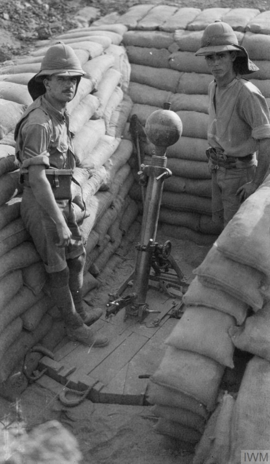
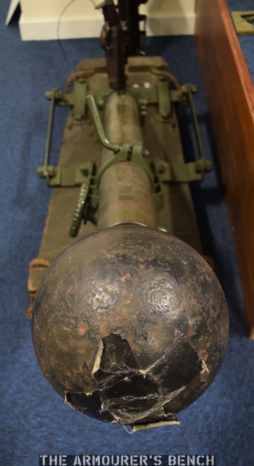
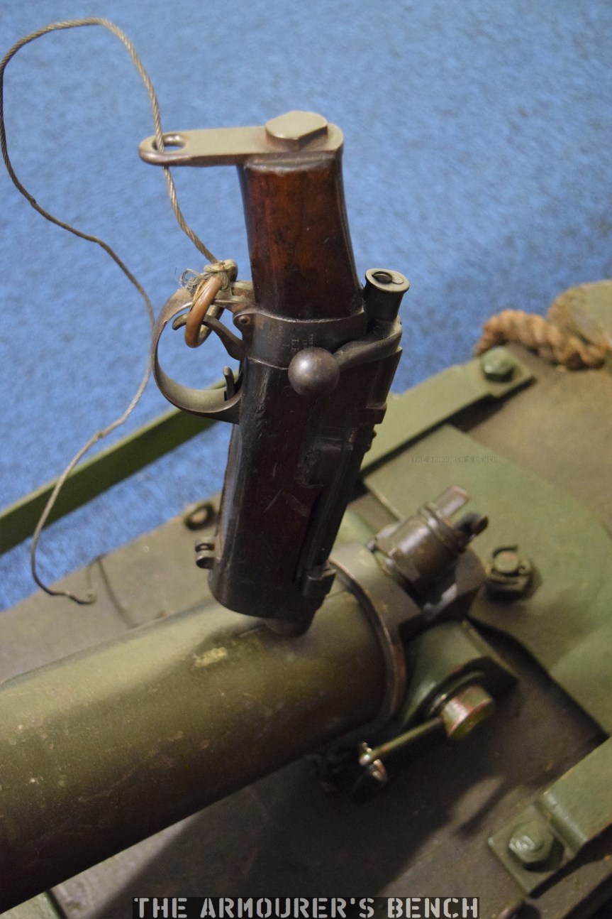
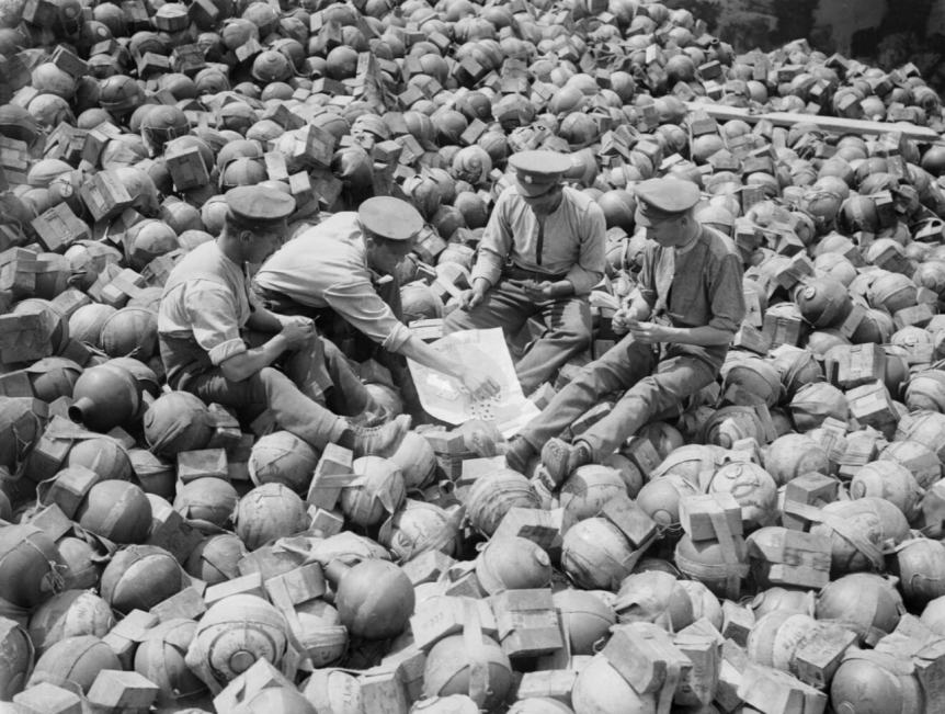
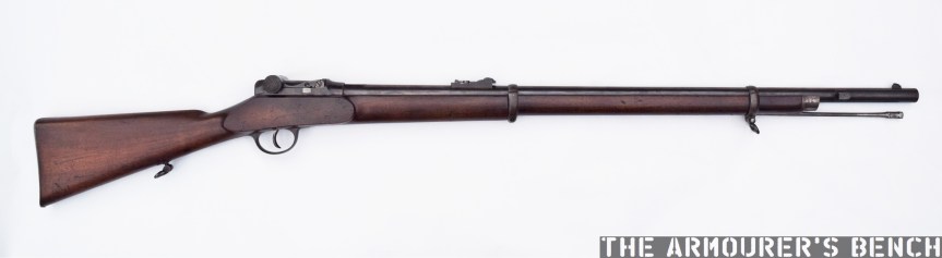
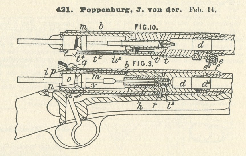
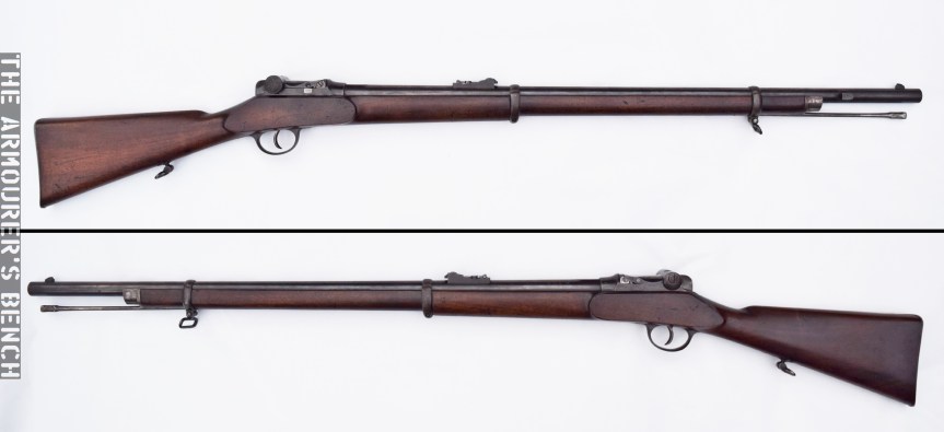

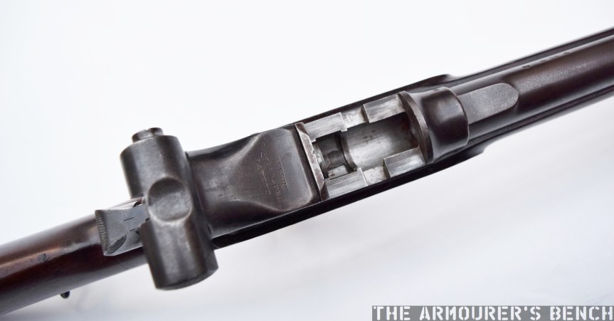


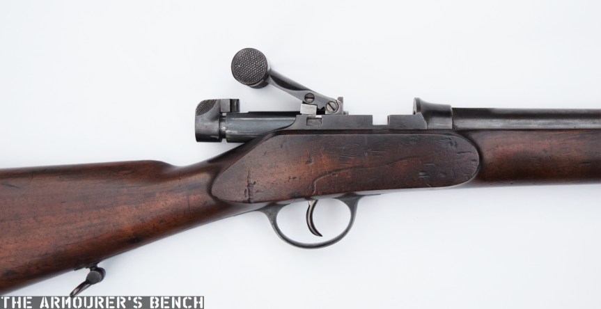
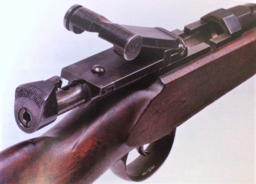
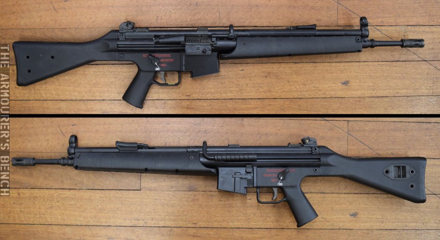
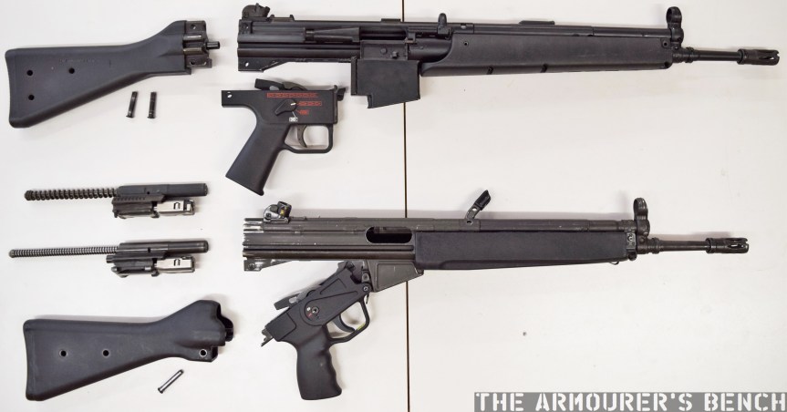
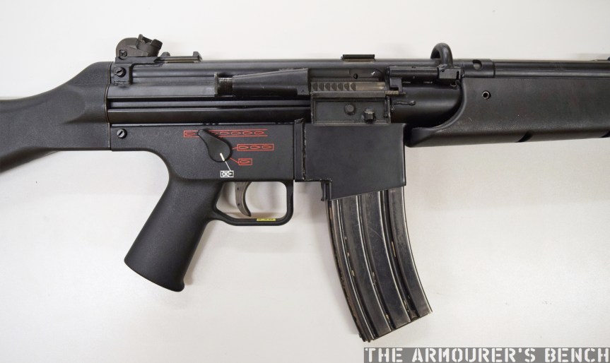

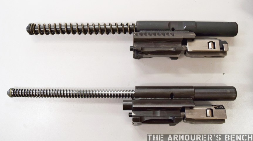
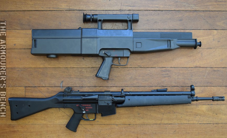
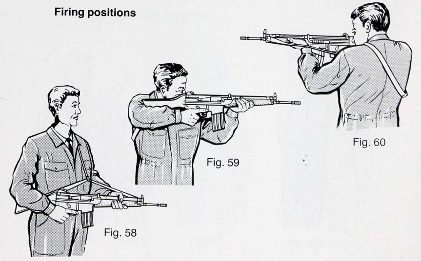
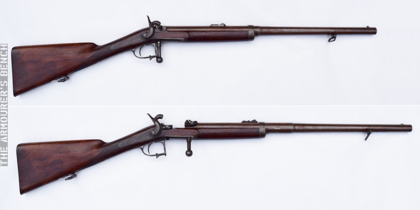
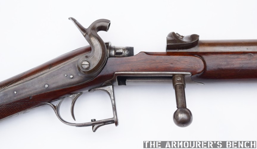
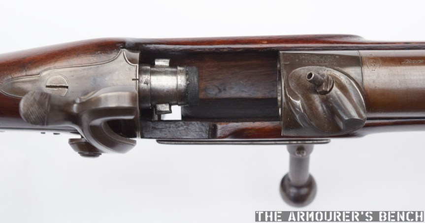
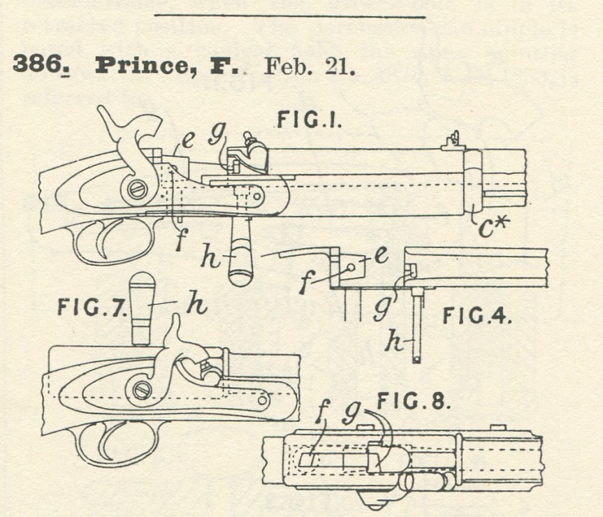
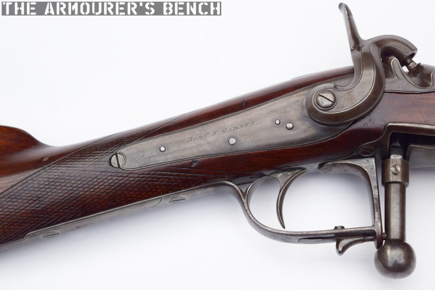
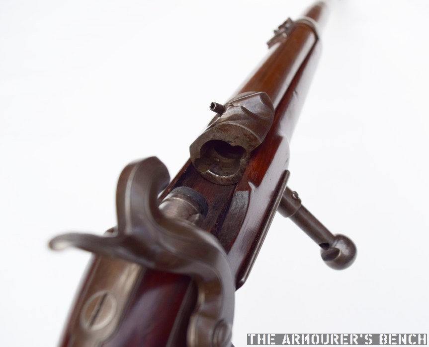
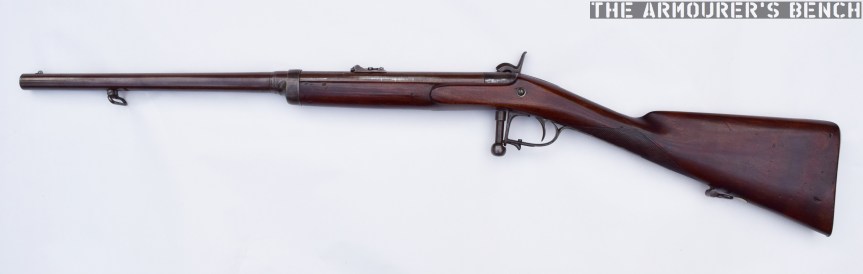
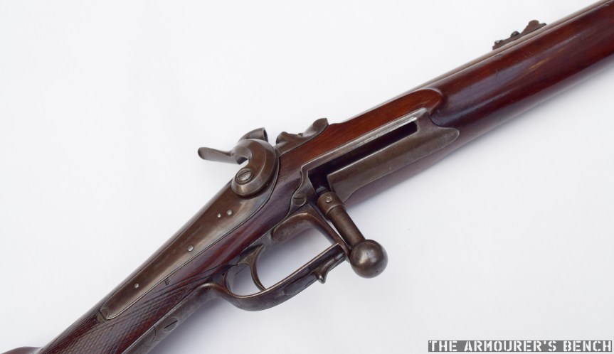
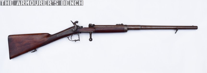
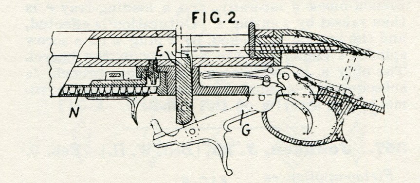
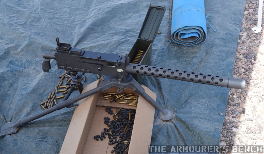


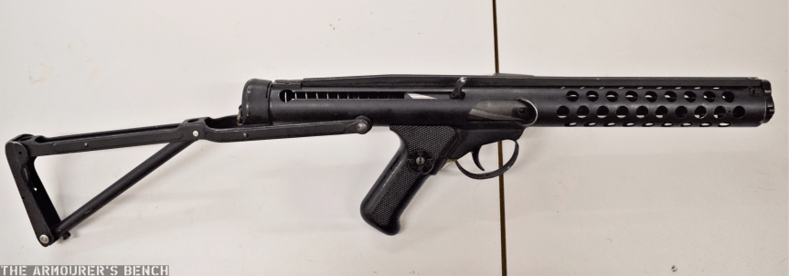
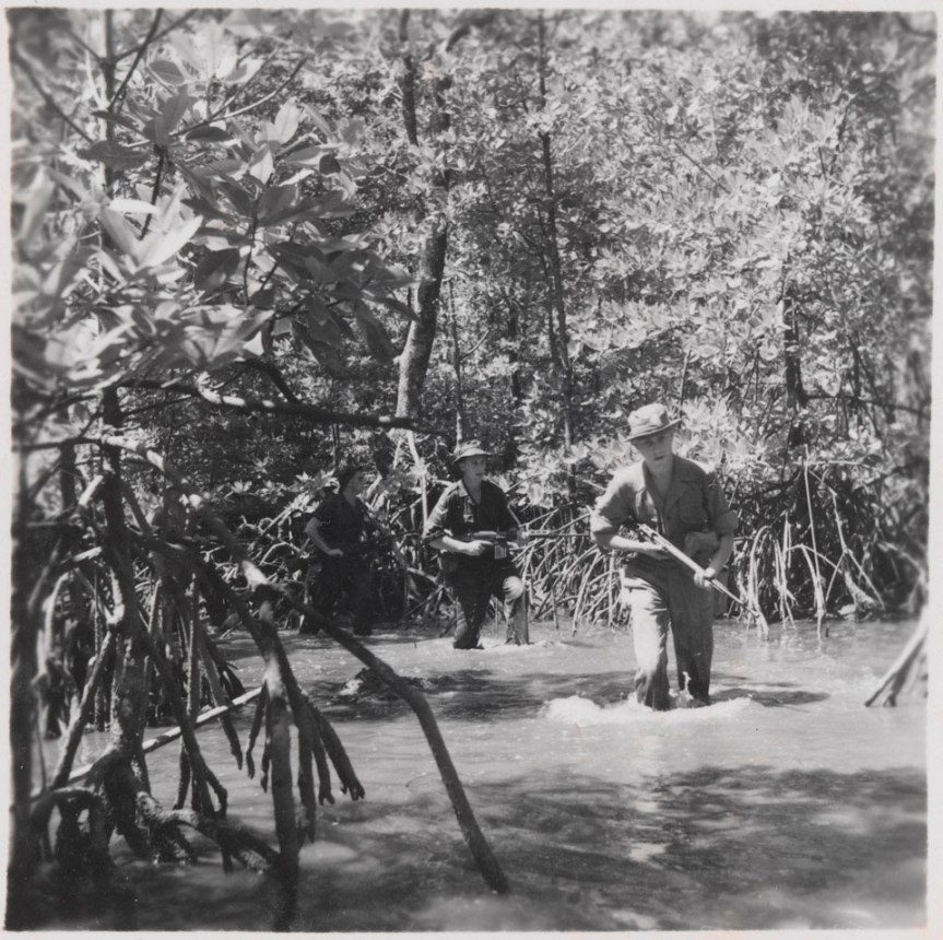

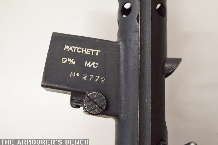
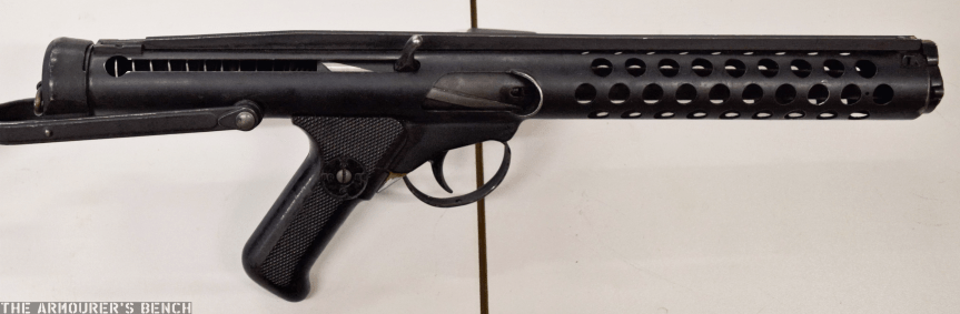

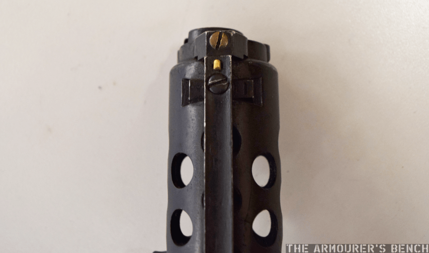
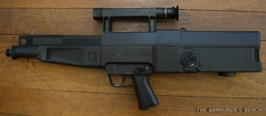
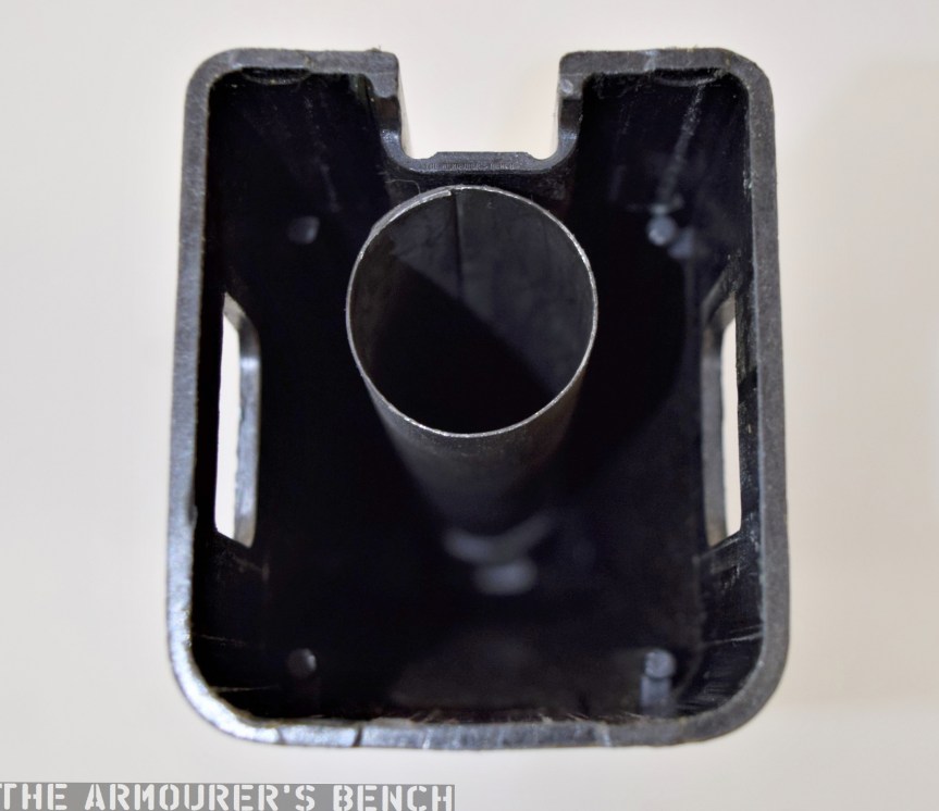

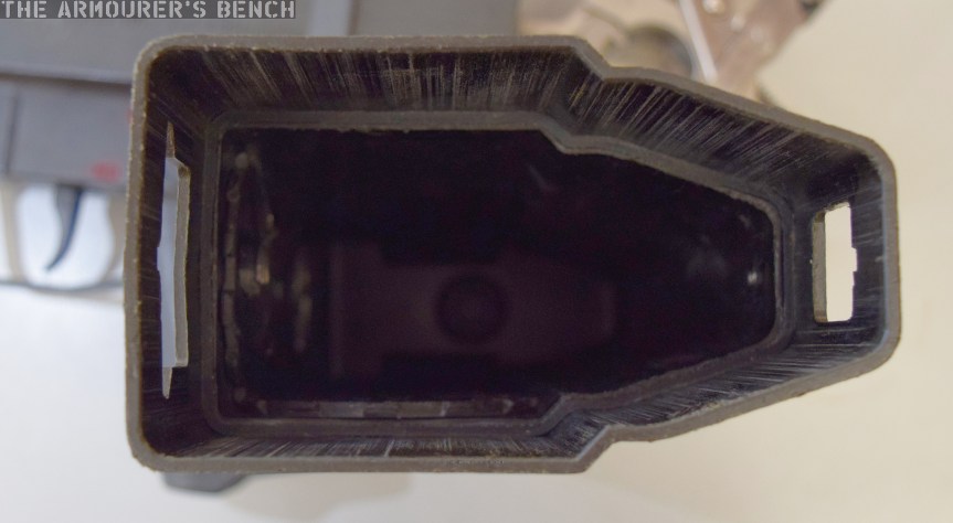
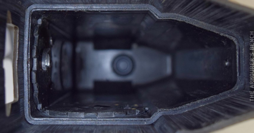
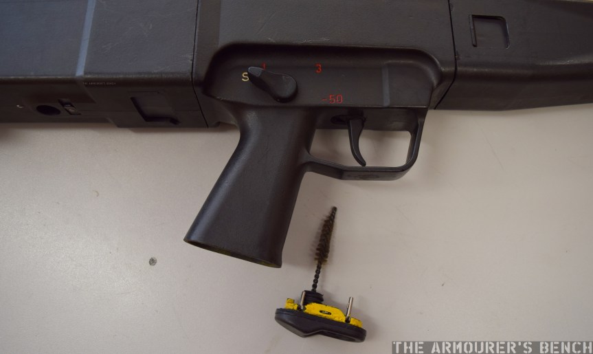
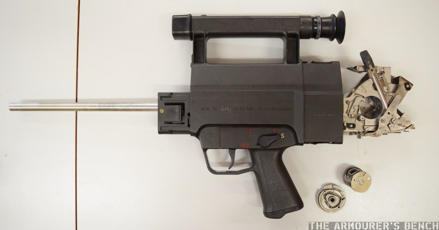
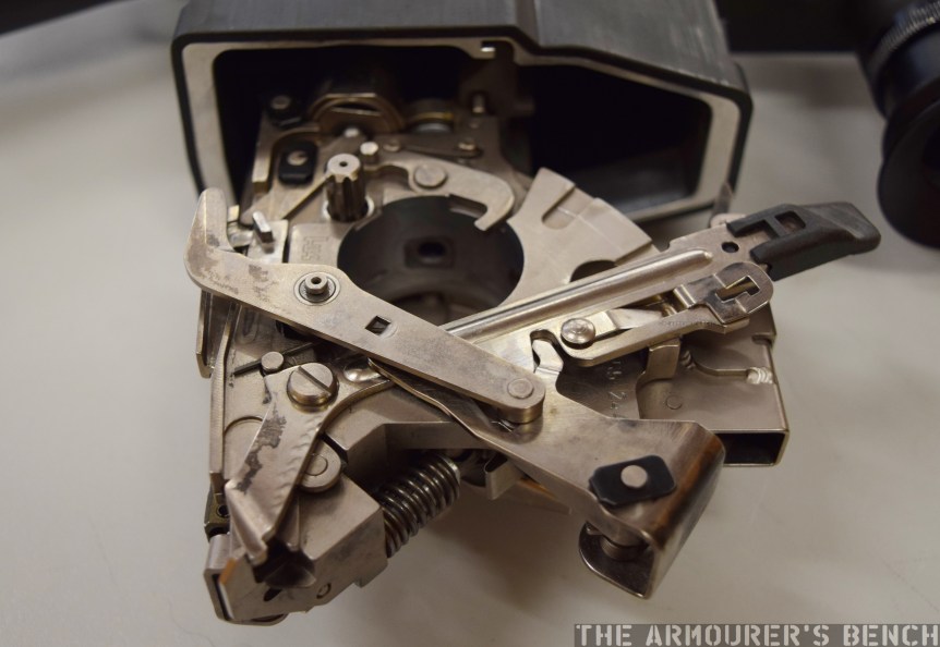

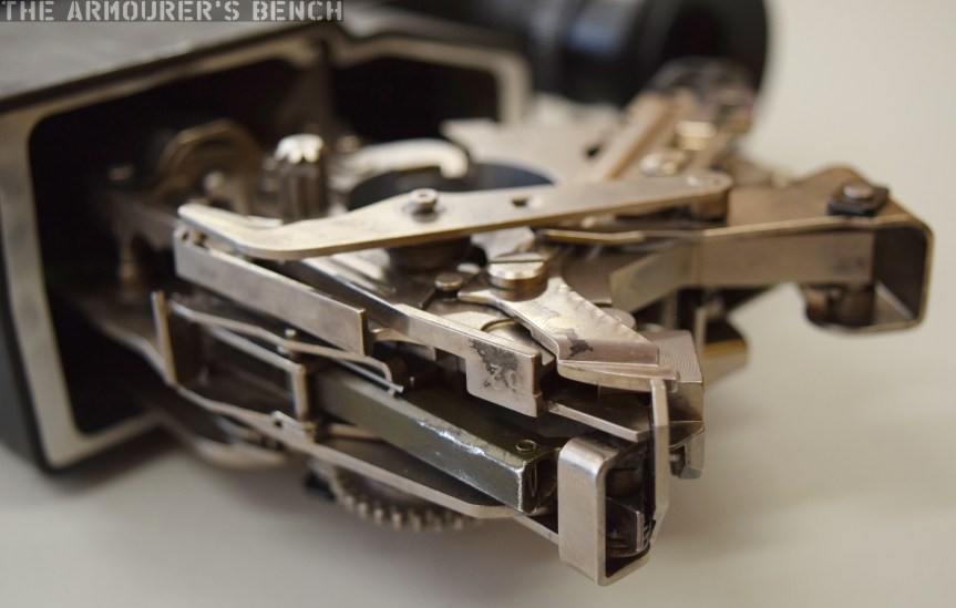

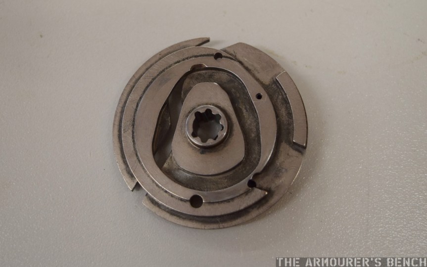


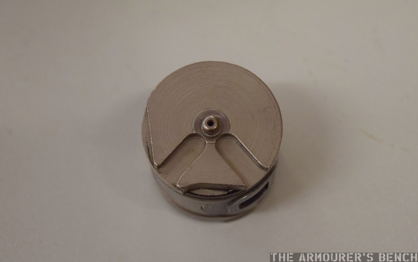
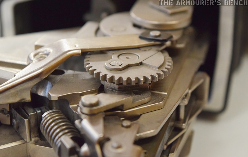
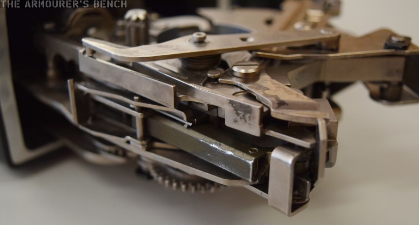
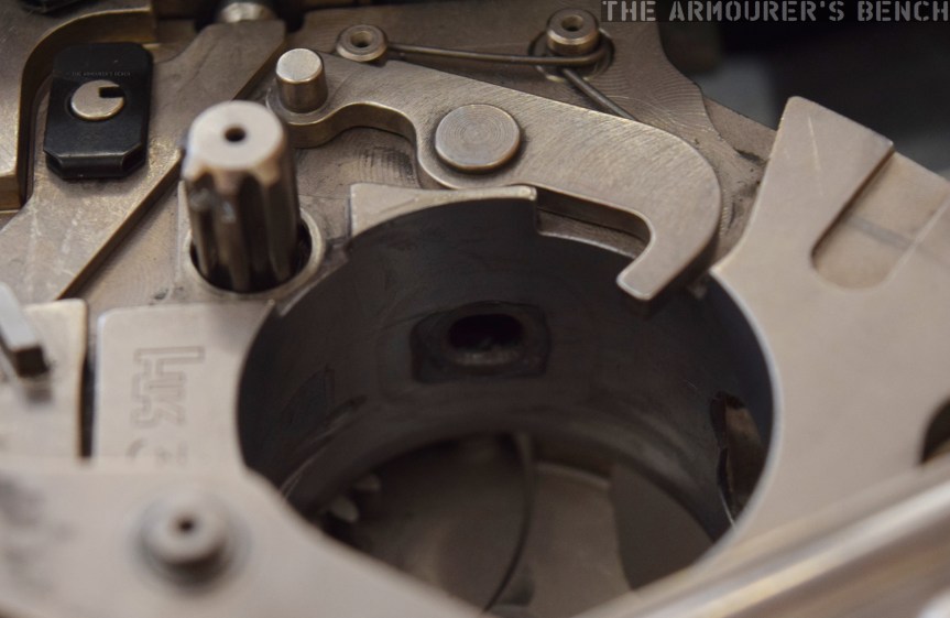
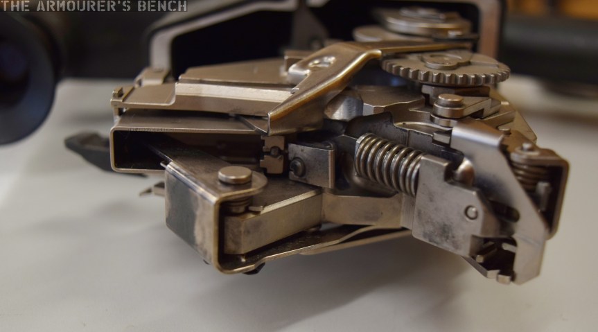
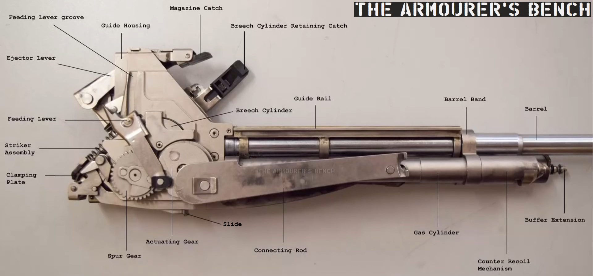
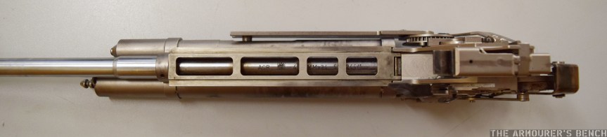
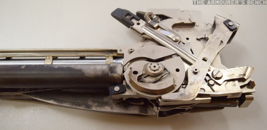
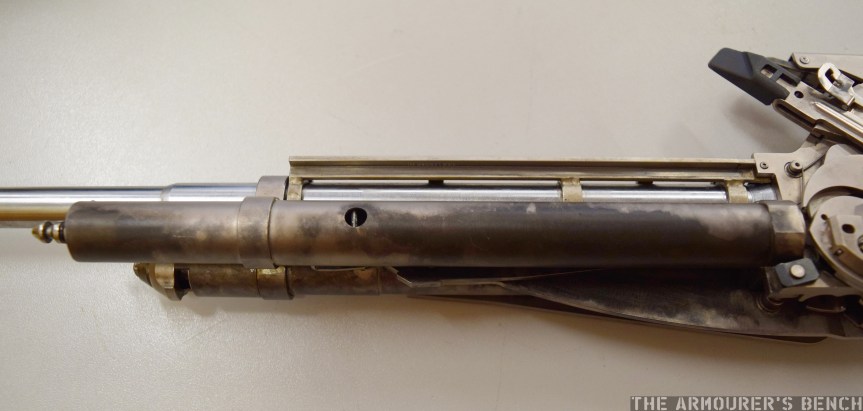
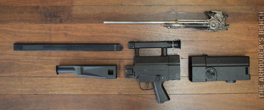


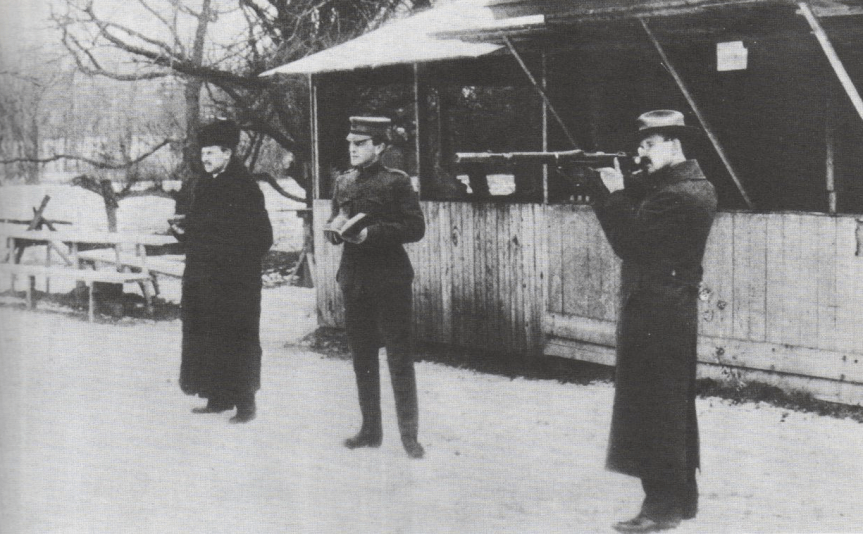
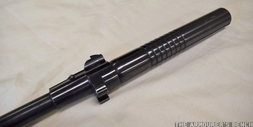
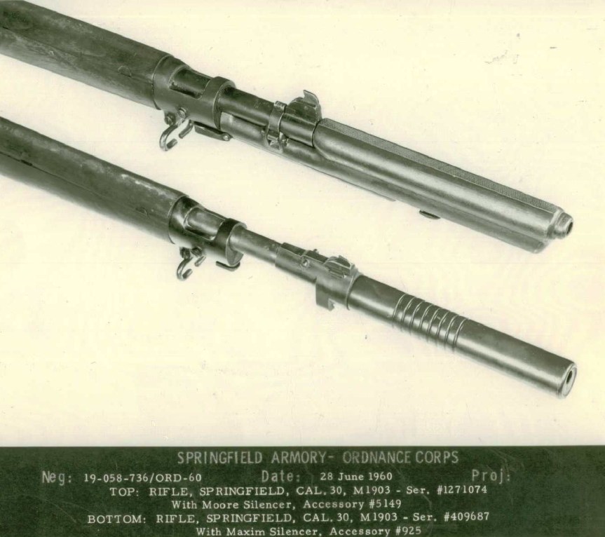


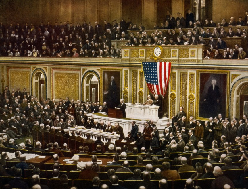
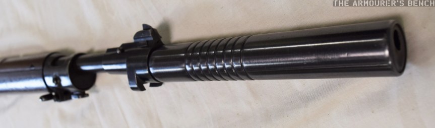

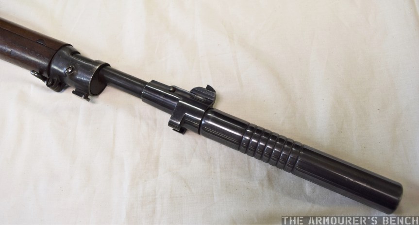
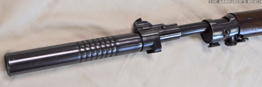
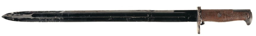
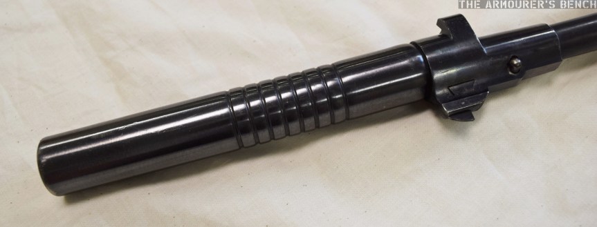
