It’s essential for soldiers to know how to use and maintain their weapons properly. We’ve been collecting training manuals, pamphlets and handbooks (as part of the TAB reference collection) to give us a wider understanding of how troops were trained and how they used their weapons.
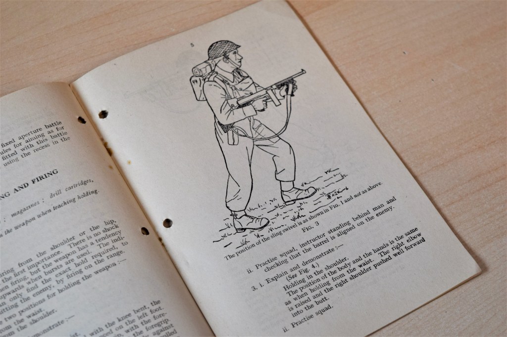
In this video we take a look at the British Army’s 1942 small arms training pamphlet for the ‘Thompson Machine carbine’.
Diagram showing firing the hip (Matthew Moss)
The pamphlet, issued in July 1944, is written for instructors to train troops how to handle, maintain and use the Thompson. The pamphlet was eventually superseded by one covering both the STEN and Thompson.
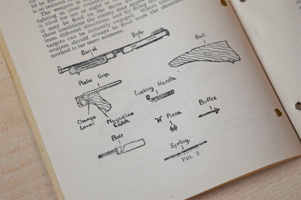
Diagram showing the Thompson Machine Carbine disassembled (Matthew Moss)
The pamphlet is just 12 pages long but includes some interesting insights and an appendix looking at the ‘spotlight projector’ training instrument.
If you enjoyed these videos and this article please consider supporting our work here. We have some great perks available for Patreon Supporters. You can also support us via one-time donations here.Thank you for your support!
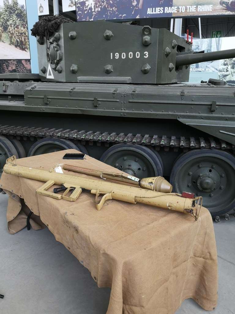
Here’s a behind the scenes look at the filming Matt did at The Tank Museum for the upcoming ‘Rhineland 45 – Decision in the West’ documentary being produced by Realtime History, the guys behind The Great War!
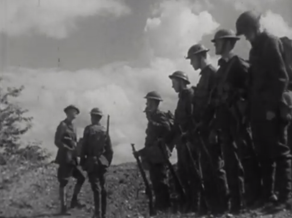
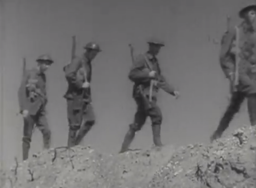
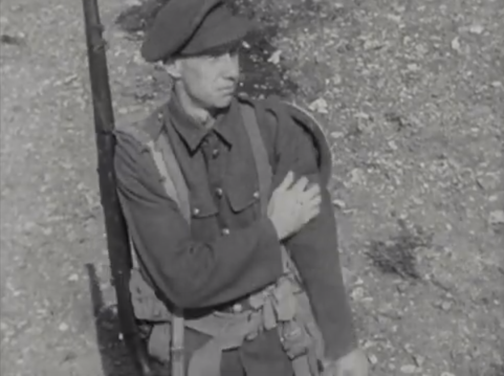
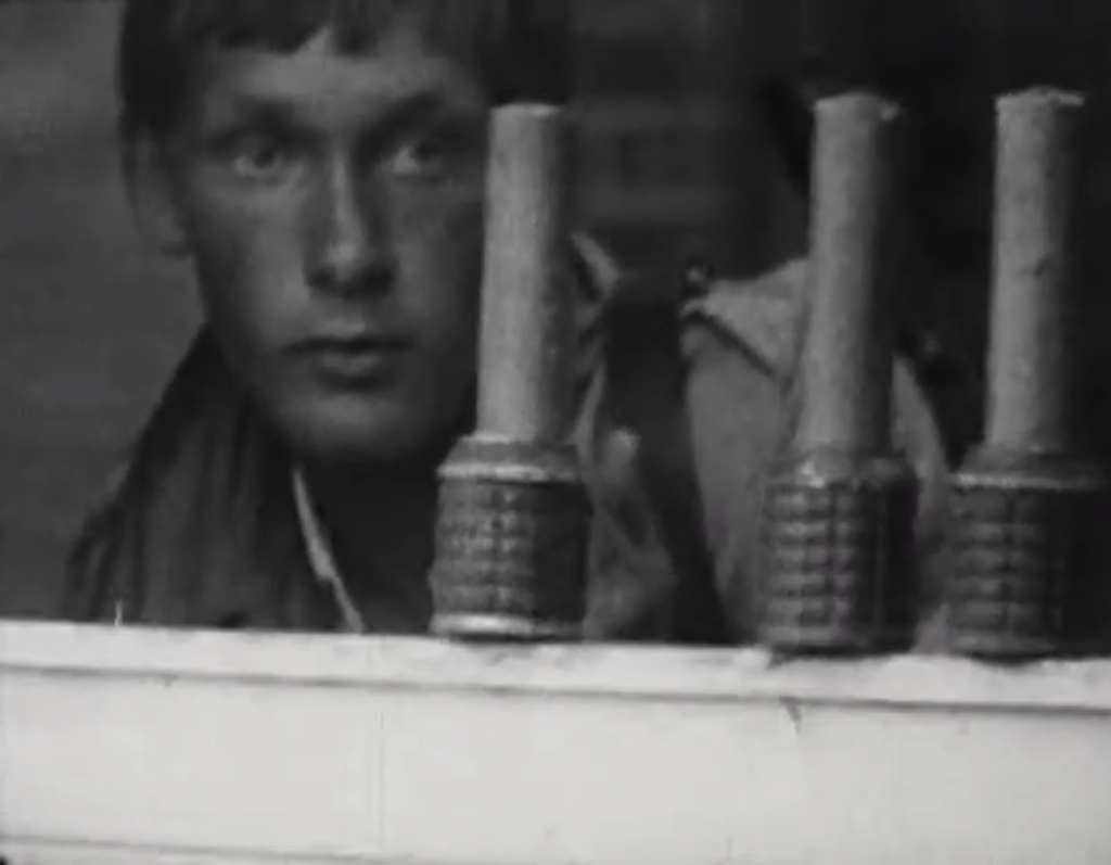
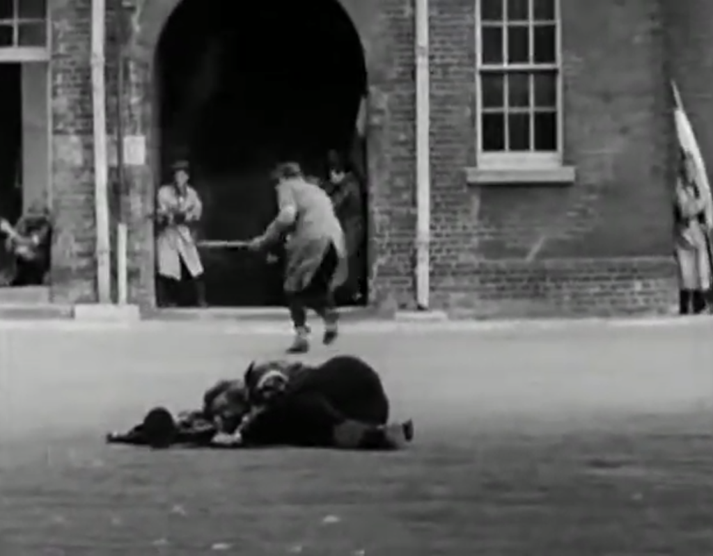
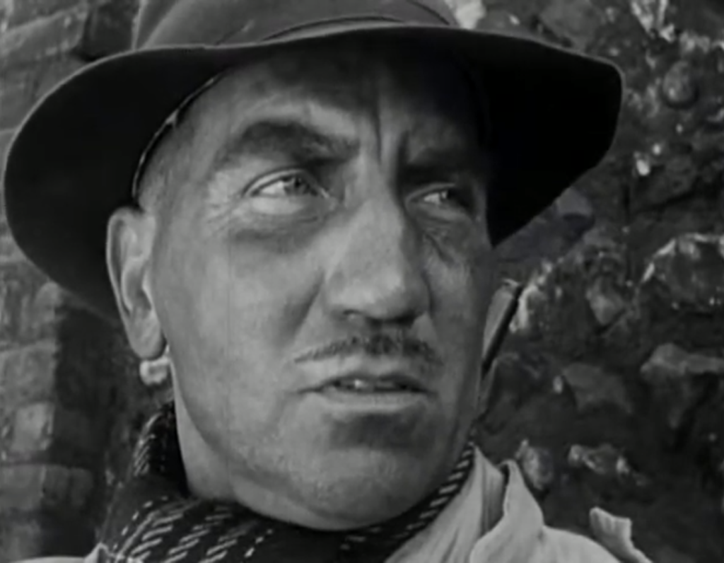
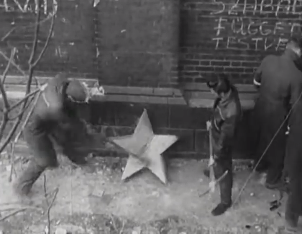
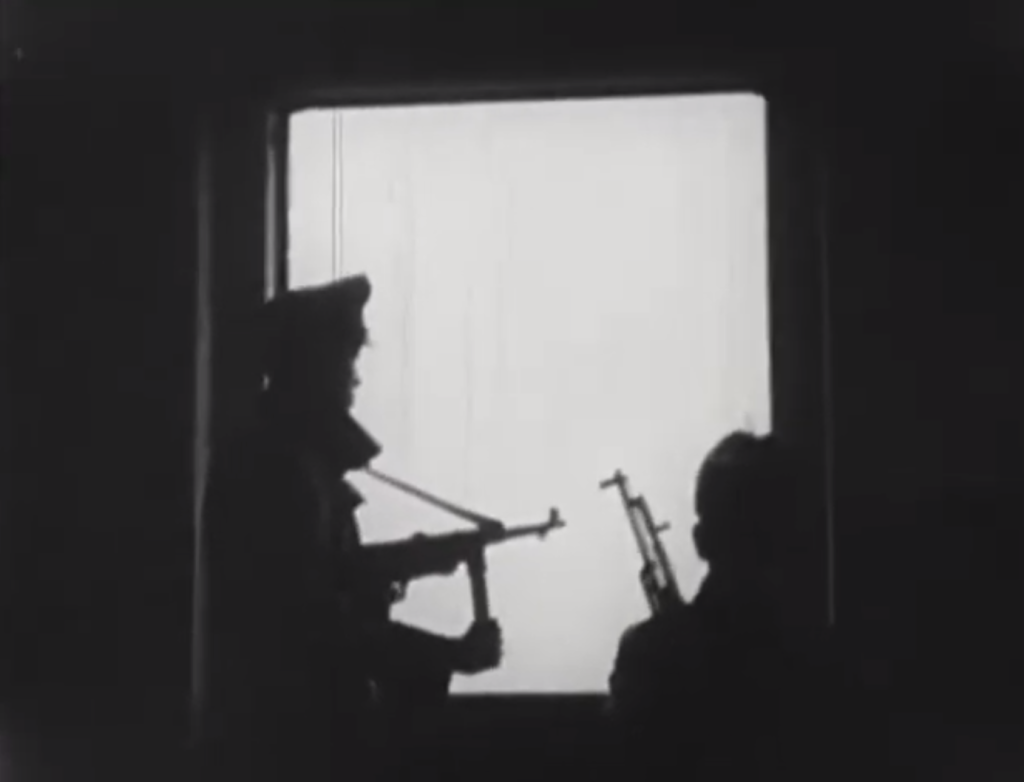
This week we look at two of acclaimed British director Peter Watkins’ formative amateur films: The Diary of an Unknown Soldier (1959) & The Forgotten Faces (1960). Perhaps best known for his later 1964 film Culloden and 1965’s ground-breaking nuclear war film The War Game. These two early films are especially fascinating as you can see Watkin’s distinct style develop through them.
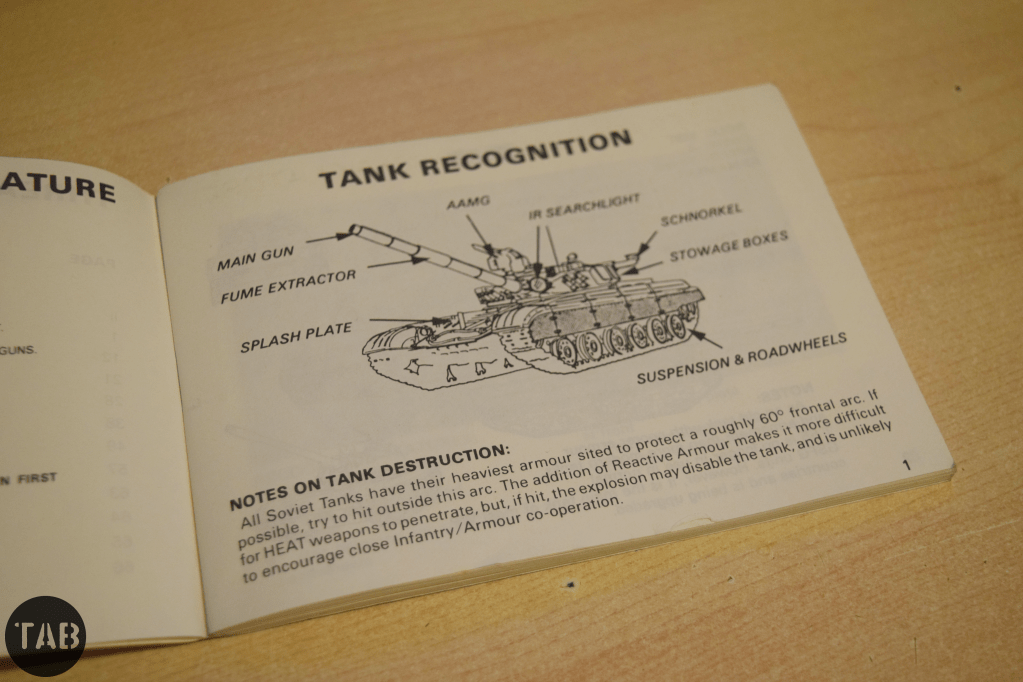
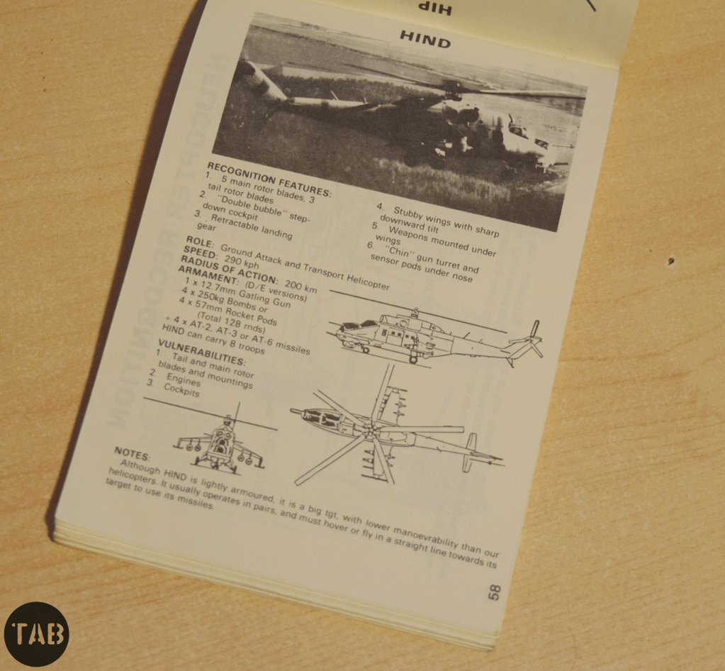
It’s the 1980s and the British Army Of the Rhine is still stationed in West Germany facing down the USSR’s forces. The Cold War has gotten hot and the 3rd Shock Army is approaching your dugout but how do you differentiate a BTR from a BMP? This handy British Army THREAT Recognition Guide booklet gives you everything you need to know about the Soviet armour, infantry and aircraft you’re facing!
Continuing on from our earlier look at a British Army threat Recognition Guide to Iraqi Ground Forces issued during the Gulf War, we dig into the TAB reference collection again and take a look at this Threat Recognition Guide looking at Soviet air and ground forces facing the British Army of the Rhine in the 1980s.
The Group of Soviet Forces in Germany (GSFG) in East Germany throughout the Cold War were an ever present threat to West Germany and NATO. This recognition guide covers all of the USSR’s main battle tanks, armoured personnel carriers, and infantry fighting vehicles, as well as artillery systems and some of the close support aircraft which would have accompanied the attacking Soviet forces.
The pages of the recognition guide include photographs, diagrams, basic specs and recognisable features of the various enemy vehicles. It was put together by the Intelligence Directorate of BAOR’s 1 Corps.
If you enjoyed these videos and this article please consider supporting our work here. We have some great perks available for Patreon Supporters. You can also support us via one-time donations here.Thank you for your support!
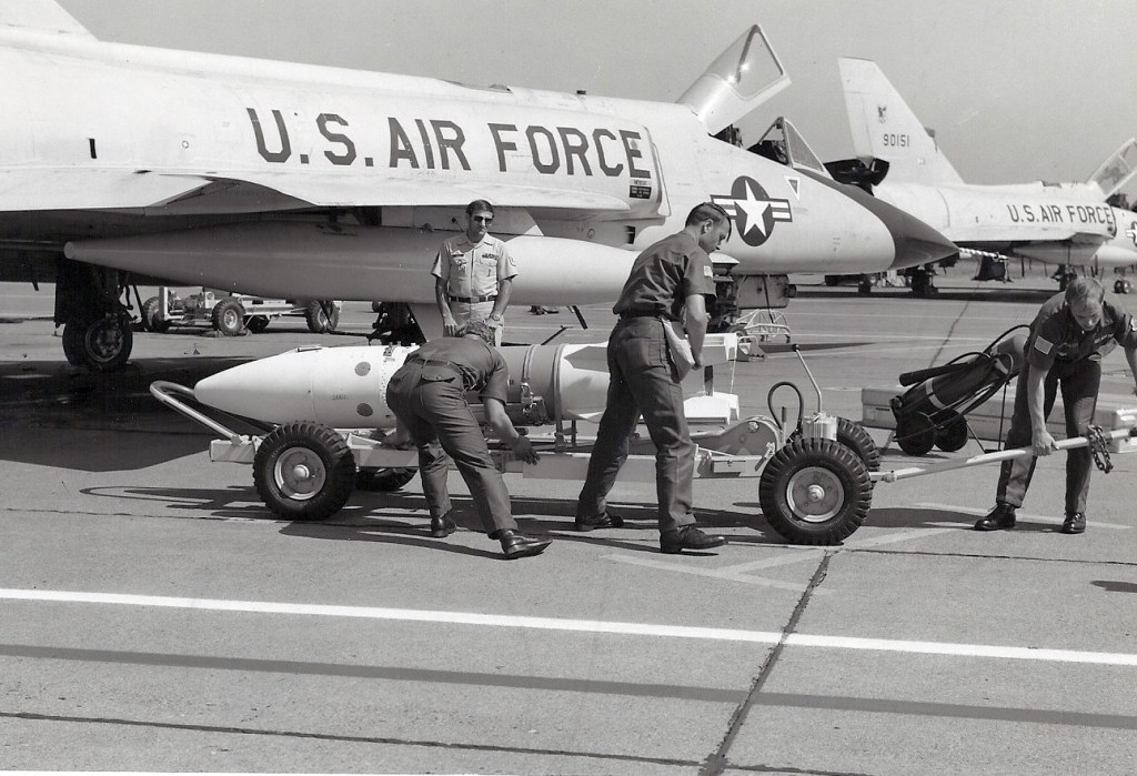
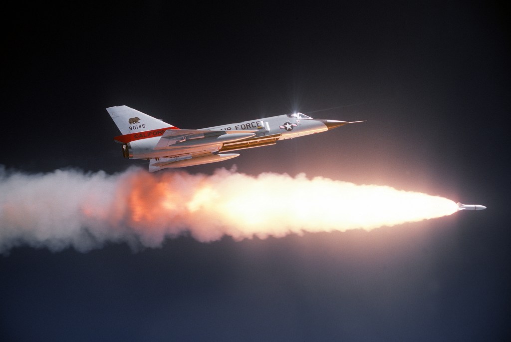
The MB-1/AIR-2 ‘Genie’ was the world’s first nuclear-armed air-to-air weapon and remains the most powerful missile ever deployed aboard U.S. Air Force interceptors. Developed as the Cold War began to heat up it would be carried aboard a succession of aircraft including the F-89, F-101B Voodoo, and the F-106 Delta Dart.
The MB-1 (later the AIR-2) was an air to air rocket with a 6 mile range and a 1.5 kiloton W25 nuclear warhead. It was ostensibly a tactical nuclear weapon designed to take on Soviet strategic bomber formations. The early 1950s saw the Soviet Union’s strategic bomber capability expand from the Tu-4, B-29 Superfortress copy, to include the Tupolev Tu-16 and Tu-95 and the Myasishchev M-4. These new long-range, nuclear capable bombers posed a serious threat to the continental United States. It was decided that only nuclear anti-aircraft weapons could counter the new high-flying Soviet bombers. Development began in 1954 with the project code-named “Genie” by the Air Research and Development Command.
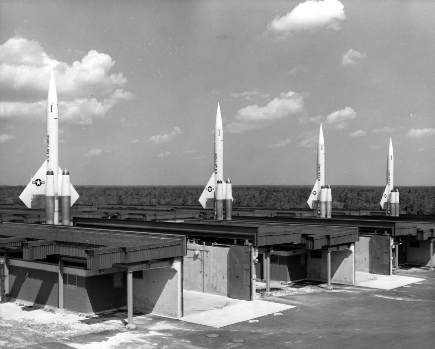
We’ve previously looked at the Boeing BOMARC, the world’s first long-range surface to air missile, whose role was similar to the air-launched MB-1 – to engage incoming Soviet bombers. During the early 1950s, before the emergence of ICBMs, the USAF expected the main nuclear threat to the United States to come via massive attacks by Soviet long-range bombers carrying atomic bombs.
The USAF hoped that weapons like the BOMARC and the MB-1 would be able to engage and neutralise large soviet formations before they reached their targets. This would be achieved by USAF interceptors scrambled to meet the incoming Soviet aircraft, the interceptors would move into engagement range and launch their MB-1 missiles, turning away to avoid the blast. The Genie would detonate inside or near the Soviet formations breaking up their attack. For this role, attacking massed enemy aircraft, the Genie certainly appears to be an efficient weapon concept. However, like the BOMARC it quickly became obsolete as the Soviets moved away from strategic bomber aircraft and embraced long-range intercontinental ballistic missiles.
BOMARC Site No. 1 at McGuire Air Force Base (USAF)
Development of the MB-1 was carried out by the Douglas Aircraft Company. Physically, the plump-looking air-to-air nuclear rocket was 9ft 2in long and 17.5in in diameter, weighing in at just over 820lbs (372kg). The weapon had four fins, which spanned over 3 feet, these deployed once launched and helped to stabilise the Genie’s flight.
The Genie carried a 1.5-kiloton W-25 nuclear warhead and was powered by a solid-fuel rocket engine developed by Thiokol. It could reach speeds up to Mach 3.3 and travel just over 6 miles before detonating. It’s effective blast radius was estimated to be just short of 1,000 feet (300m), the Genie relied upon this area effect as guidance systems small enough to be fitted to a missile were in their infancy, as a result the Genie was essentially an unguided rocket with no onboard guidance.
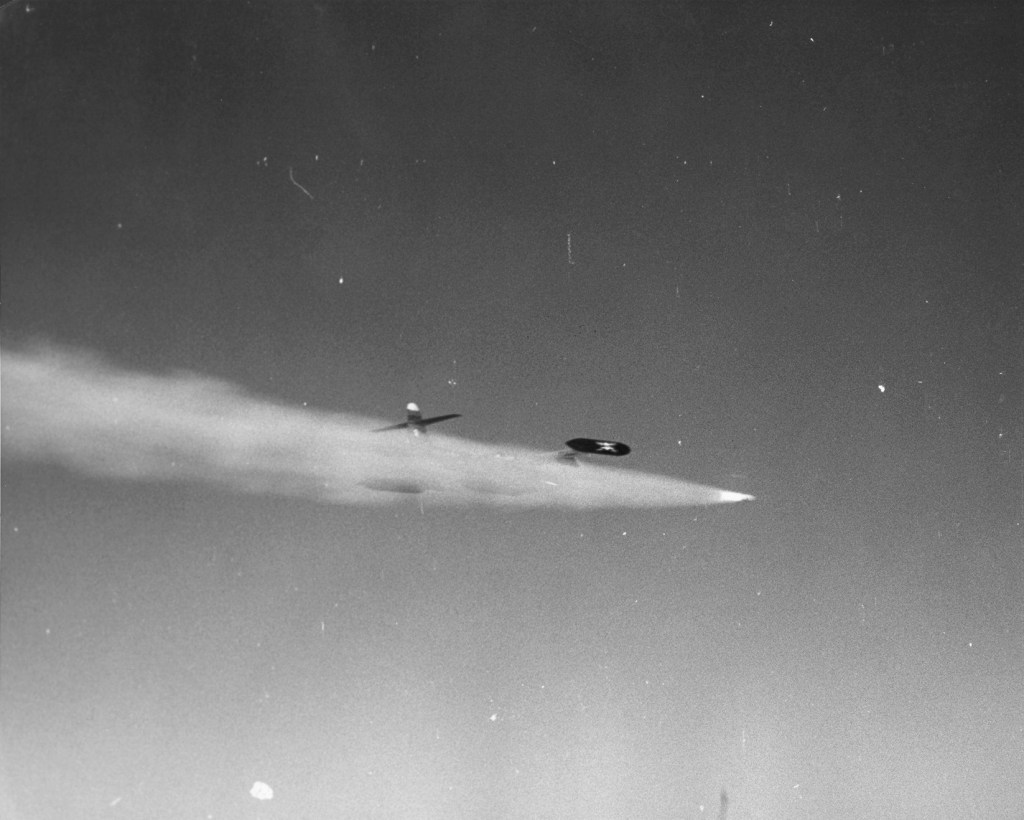
An Northrop F-89J has the distinction of being the only aircraft to fire a live MB-1 Genie during the Operation Plumbbob tests on 19th July, 1957. The F-89 was flown by Captain Eric W. Hutchison, with Captain Alfred C. Barbee acting as Radar Intercept Officer. They launched the Genie at around 18,500 feet, the nuclear-tipped Genie accelerated to Mach 3 and travelled 2.6 miles in less than 5 seconds. While operationally the weapon would have detonated by a time-delay fuse the Plumbbob detonation was triggered by a signal from the ground.
The F-89, flown by Captain Eric W. Hutchison, firing a live MB-1 during Operation Plumbbob’s Test Shot John, 1957 (National Nuclear Security Administration)
Test shot John was a form of controlled human testing, with not only those on the ground, beneath the blast tested for radiation dose sizes but also the crews of the aircraft that launched the rocket. This contemporary film about the test notes that “neutron and gamma doses for the three crews did not exceed 5 Reps and 3 Roentgens respectively.
A later report noted:
“Neutron and gamma radiation dosages received by the crew members were less than had been predicted. To some extent this may he attributed to the effect of aircraft shielding. which was not utilized in the theoretical predictions. No crew member received more than 5 Reps neutron and 3r gamma during his participation. The experiment proved that the MB-1 air-to-air rocket can be successfully launched by the F-89 aircraft at 19,000 feet MSL with a radiation dose to the delivery crew within acceptable limits.”
The yield of the explosion was estimated to have been 1.7 kilotons. 18,500 feet below, at ground zero, five USAF officers and a photographer volunteered to stand under the blast to prove that the weapon was safe for use over populated areas. The radiation doses received by the F-89 crew and the men on the ground were reportedly small.
An F-106 Delta Dart aircraft after firing an ATR-2A missile over a range. The aircraft is assigned to the 194th Fighter Interceptor Squadron, California Air National Guard (USAF)
The MB-1 became the primary air to air weapon of the F-106 Delta Dart, this footage includes and illustration showing how the MB-1 was deployed from the F-106 as well as some of the live missile tests with inert missiles during the development of the Delta Dart’s launch system for the Genie.
Douglas built more than 1,000 Genie rockets before terminating production in 1962. In June 1963, the MB-1 Genie rockets were re-designated in the AIR-2 and later the ATR-2A. The USAF’s operational deployment of the Genie ended in late 1980s with the retirement of the last F-106 Delta Darts. The Genie’s other operator, the Royal Canadian Air Force, continued to operate the Genie aboard until 1984.
Bibliography:
OPERATION PLUMBBOB, Technical Summary of MiIitary Effects, 1962, Defense Atomic Support Agency, (source)
‘MB-1 Documentary’, Douglas Aircraft Company via US National Archives, (source)
‘Five Men at Atomic Ground Zero’ Operation Plumbbob Test Shot John footage, Atomic Central, (source)
‘The F102A – F106A Annual Review 1957’, technical review of the Delta Dagger, USAF via San Diego Air and Space Museum Archives, (source)
’19 JULY 1957 – FIVE AT GROUND ZERO’, CTBTO, (source)
If you enjoyed these videos and this article please consider supporting our work here. We have some great perks available for Patreon Supporters. You can also support us via one-time donations here.Thank you for your support!
So you may have seen our earlier video looking at the portrayal of PIATs in the 1978 classic A Bridge Too Far! If not check it out.
When I think of Richard Attenborough’s all-star war epic telling the story of Operation Market Garden, I immediately think of the iconic ‘BRING UP THE PIAT’ scene where Anthony Hopkins playing Colonel John Frost commanding 2 PARA calls for the Projector, Infantry, Anti-Tank to take out a marauding ‘Panther’.
But this isn’t the only scene from the film depicting the PIAT! In this video we’ll look at a couple of the other scenes showing the PIAT in action.
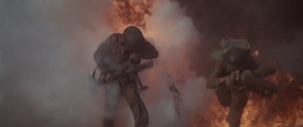
We first see the PIAT during the scene when the Guards Armoured Division’s spearhead meets heavy german resistance. Michael Caine’s Sherman’s get a pasting from some Pak 40s. The British infantry deploys and we see a cornucopia of kit ranging from Brens to Vickers to an M2 Browning. But blink and you’ll miss them a pair of PIAT teams also ‘bring up the PIAT’. A two man team can be seen moving forward, the No.1 carrying the PIAT and the No.2 carrying a 3 round bomb carrier, sadly killed by enemy fire.
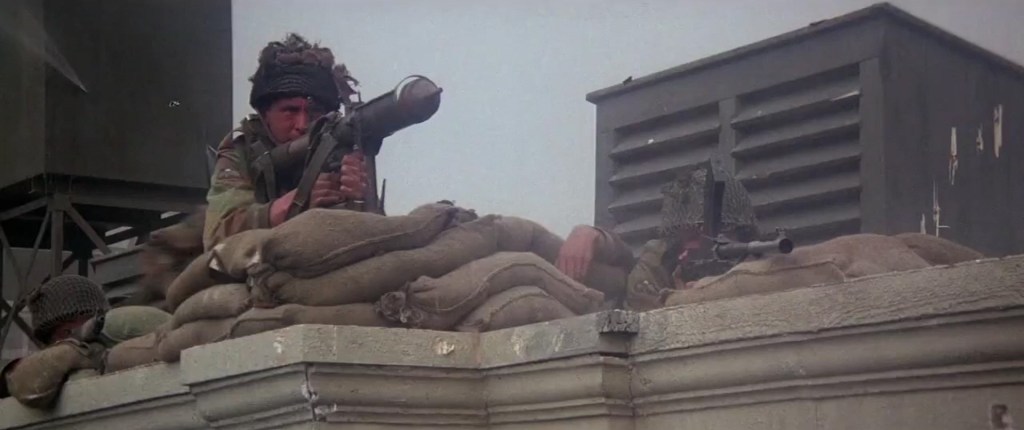
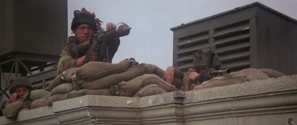
The second scene in which we see the PIAT finally get to work on some German armoured fighting vehicles is during Gräbner’s attack over the bridge. As the PARAs at the Bridge prepare for the attack we see 2 or 3 PIAT positions get ready – loading bombs into their bomb support trays. One PIAT No.1 can be seen slotting the rear of a PIAT bomb into the projectile guide plates to hold the bomb in place – very authentic.
As the column crosses the Bridge Frost orders his men to open fire, Brens, Stens, Rifle No.4s and PIATs open up and the column is stopped in its tracks. During the scene we see a number of PIAT’s fire and knock out SS vehicles. One PIAT No.2 is hit by enemy fire. The first PIAT round fired hits a lead German vehicle causing it to halt, the second flips a Kubelwagen. We then see a No.2 two load a fresh bomb into the bomb support tray – with a tap to make sure its properly in place. We get a great show of the PIAT firing from the front. It’s worth noting that the PIAT doesn’t recock and the spigot is still seen in the bomb tray just before the camera cuts away. Meaning that that PIAT No.1 will have to recock his weapon before he can fire again!
It’s worth remembering without the ‘Bring Up The PIAT’ scene making a point of naming the weapon, most people would never have known what this unusual weapon that dealt so much damage in the earlier scene was! Of course the attack wasn’t stopped by PIATs alone, there were also airborne anti-tank guns, which the film doesn’t show.
Another little titbit of information I learnt since the first ‘Bring Up The PIAT’ video, thanks to my friend Robbie of RM Military History [check out his channel], is that the PIAT was fired in most of these scenes by one of the film’s armourer Bill Aylmore. The information comes from After the Battle – The Battle of Arnhem – War Film: A Bridge Too Far which describes him as formerly a sergeant with the 50th Regt. – which might be a reference to the Queen’s Own Royal West Kent Regiment. The book goes on to say that “Aylmore excelled himself during the filming of the battle on the bridge by being the ace shot with the PIAT. During all the various takes he was able to put the bomb exactly where the director wanted it and where it coincided with the special effects explosions.” – Good shooting indeed!
If you enjoyed these videos and this article please consider supporting our work here. We have some great perks available for Patreon Supporters. You can also support us via one-time donations here.Thank you for your support!
In this video we’ll be launching a brand new series where we’ll look at period small arms and light weapons manuals and other ephemera like infantry tactics handbooks and recognition guides.
This month marks the 30th anniversary of what the British Army called Operation Granby, better known as Desert Storm or the Gulf War. So I thought taking a look at a Recognition Guide to Iraqi Ground Forces issued during Granby would be a good place to start!
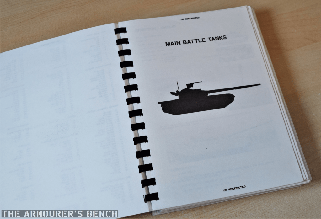
Chapter page for Main Battle Tanks (Matthew Moss)
Britain deployed more than 53,000 personnel during the operation, which began in August 1990, just after the invasion of Kuwait, with the arrival of 2 squadrons of Tornados in theatre. The first ground forces, elements from 7 Armoured Brigade began arriving in October. With no ready reaction force a division strength force was cobbled together from units deployed in Germany and the UK. Huge logistical constraints were overcome to provide a full armoured division, consisting of two brigades, for the liberation of Kuwait.
The guide’s entry for the AMX 155 F3 (Matthew Moss)
During the ground phase of the operation (Operation Desert Sabre), which began on 24th February 1991, British armoured and mechanised forces, part of VII Corps, provided the left-hook of the allied assault. The division’s two armoured brigades leapfrogging one another quickly taking successive objectives and sweeping west through occupied Kuwait, towards the Gulf Sea, neutralising Iraqi positions with relative ease. During less than 100 hours of ground combat British forces travelled 180 miles and destroyed approximately 300 Iraqi vehicles while allied forces as a whole captured an estimated 80,000 Iraqi troops. A total of 47 British troops were killed during Granby. A ceasefire was declared on 28 February with Iraqi forces collapsed and Kuwait liberated.
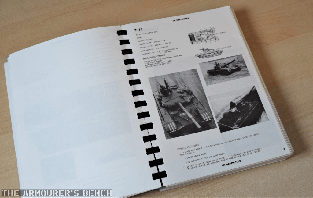
The guide’s entry for the T72 tank (Matthew Moss)
The guide was compiled by the Recognition Materials Cell at the Joint Air Reconnaissance Intelligence Centre (or JARIC). Formed in 1953, from the Central Interpretation Unit and based at RAF Brampton from 1957 to 2013, JARIC was the UK’s strategic imagery intelligence provider – providing analysis of aerial and later satellite photography or enemy assets.
With war with Iraq looking imminent and substantial British forces deployed from the UK and Germany, JARIC were tasked with putting together a recognition guide covering Iraqi and Kuwaiti ground assets captured by Iraq during the invasion of Kuwait.
The infamous SCUD (Matthew Moss)
This included everything from main battle tanks, reconnaissance vehicles and armoured personnel carriers to self-propelled artillery, mortars, artillery and multi-barrelled rocket launchers. It also included anti-tank missiles, surface to air missile systems and anti-aircraft assets as well as engineering equipment. All of which might be encountered during upcoming operations to liberate Kuwait. Let’s take a look.
The guide sadly doesn’t have a scale of issue list so it’s difficult to know how many were printed or which units received them. But the first page does give us some indication of the material’s sources – noting they are from unclassified and restricted sources – giving the book a restricted classification overall.
If you enjoyed these videos and this article please consider supporting our work here. We have some great perks available for Patreon Supporters. You can also support us via one-time donations here.Thank you for your support!
Bibliography
The Gulf War 1991, A. Finlan (2003)
Hot War, Cold War, C. McInnes, (1996)
‘Joint Air Reconnaissance Intelligence Centre (JARIC)’, National Collection of Aerial Photograph, (source)
‘Unit History: Joint Air Reconnaisance Intelligence Centre’, Forces War Records, (source)
We have examined several on screen appearances of the PIAT previously, in this article we will look at a scene from the 2014 Polish movie, MIASTO 44 or City 44/Warsaw 44. The film follows a group of young members of the Home Army during the Warsaw Uprising.
In the scene we’re going to analyse today a Home Army squad are in a defensive position on the first story of an apartment building when a German Goliath remote controlled mine approaches their position. They immediately open fire on the Goliath with small arms, some rifles, a couple of submachine guns including a Sten, a PPSh-41 and an MP40 as well as a captured MG-42. While they’re pretty well armed, they’re low on ammo.
With the small arms fire ineffectual the squad leader calls for the PIAT. The Home Army had an estimated 70 PIATs at the start of the uprising. The British Projector, Infantry, Anti-Tank was the Pole’s primary infantry anti-tank weapon. By the 12th September the allies had managed to drop more PIATs bringing the number available to around 250.
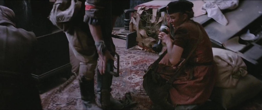
What’s so special about this scene is that it depicts the cocking of the PIAT! As the others open fire the PIAT number one can be seen rotating the outer casing to unlock it and then pulling it up until the spring inside is cocked. He then lowers the casing and locks it ready to fire. We don’t see it but the No.2 has loaded a bomb into the bomb support tray and the No.1 places the monopod on the sandbags and takes aim.
A member of the Home Army Cocking the PIAT
So not only do we have photographs of the PIAT in use at Warsaw we also have some good accounts of its use, one from Zbigniew ‘Deivir’ Czajkowski, a corporal and patrol leader with the Home Army’s ‘Parasol’ scout battalion describes using a PIAT against a German tank during street fighting. Czajkowski describes how the man about to fire the PIAT had forgotten to prime the bomb, he then describes firing on the tank below their position:
“I press the heavy weapon into my shoulder. The tank is in front of me, as if on a plate. I can see the enormous armour plating and the smoke coming from its muzzle. I set my sights. Slowly… carefully… The tank fires, below us again. I aim just behind the turret. There! I squeeze the trigger. The PIAT recoils, the round flies through the air… nearly there… It misses the tank and explodes to the rear of it. “Fuck!” Now my colleague tears the PIAT out of my hands. I don’t stop him. I load a new round. Two more shots from the tank. Presumably they haven’t noticed us. Suddenly it dawns on me – we’re on the second floor! “Aim lower, much lower, under the tracks. We’re too high up here.” The barrel of the PIAT tilts down. I’m oblivious to everything glued to the gap in the wall. The weapon barks. There’s a flash of light against the side of the tank. Got him! The tank is momentarily covered in smoke.”
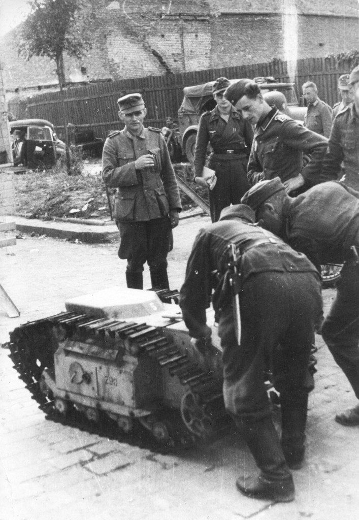
While not a tank, the Goliath seen in the film, were used during the fighting in Warsaw. The Goliaths were armoured, remote controlled bombs could be steered from cover. These tracked mines could deliver a 60 to 100kg payload of high explosive. Enough to destroy positions and heavily damage buildings. A pair of Goliaths are also seen in the earlier Polish film on the uprising – 1957’s Kanal – which also features a PIAT, albeit a wooden mock-up, which takes on a German tank.
A Goliath Remote Controlled Mine in Warsaw (Bundesarchiv)
In Warsaw 44 the PIAT No.1 manages to land his bomb just in front of the approaching Goliath, the blast apparently is enough to break one of the mine’s tracks – perhaps shrapnel or debris struck it. The victory is short-lived, however, and the Polish position is raked by machine gun fire – killing the PIAT No.1 – and a full German assault follows.
The film’s depiction of the PIAT is quite good, although the PIAT appears to be cocked very easily. The weapon’s recoil seems a little light but is represented with the No.1 being sharply pushed back. There is a short flash as the remains of the bomb’s propellent cartridge are seen as the bomb leaves the spigot. We can also see that the spigot is still visible in the bomb tray, meaning the weapon has not re-cocked itself.
The PIAT gave the besieged soldiers of the Home Army a much-needed weapon capable of taking on enemy armoured vehicles. But a few dozen PIATs weren’t enough to turn the tide and the valiant Poles were forces to surrender after two months hard fighting. The film, Warsaw 44, gives a pretty immersive idea of what the fighting in the city might have been like and is worth checking out.
Bibliography:
Miasto 44 (2014) Warsaw 1944: An Insurgent’s Journal of the Uprising, Z. Czajkowski, (2013)
If you enjoyed these videos and this article please consider supporting our work here. We have some great perks available for Patreon Supporters. You can also support us via one-time donations here.Thank you for your support!
While doing some archival digging I found some interested newsreel footage of early Cold War British missiles. The footage features the Malkara anti-tank missile and the Thunderbird surface-to-air missile.
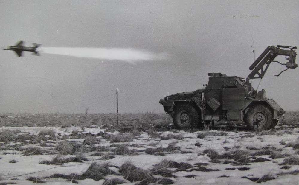
The Malkara was developed in the early 1950s. It was a wire-guided anti-tank weapon with a 57lb HESH warhead. It had a range of up to 2.5 miles. In the footage we see it guided through a hole in a target net.
FV1620 Humber Hornet launching a Malkara (ParaData)
The Malkara was mounted on a number of platforms and vehicles and remained in service into the mid-1960s. It’s bulk and weight saw it eventually replaced by the smaller Vickers Vigilant and the Swingfire.
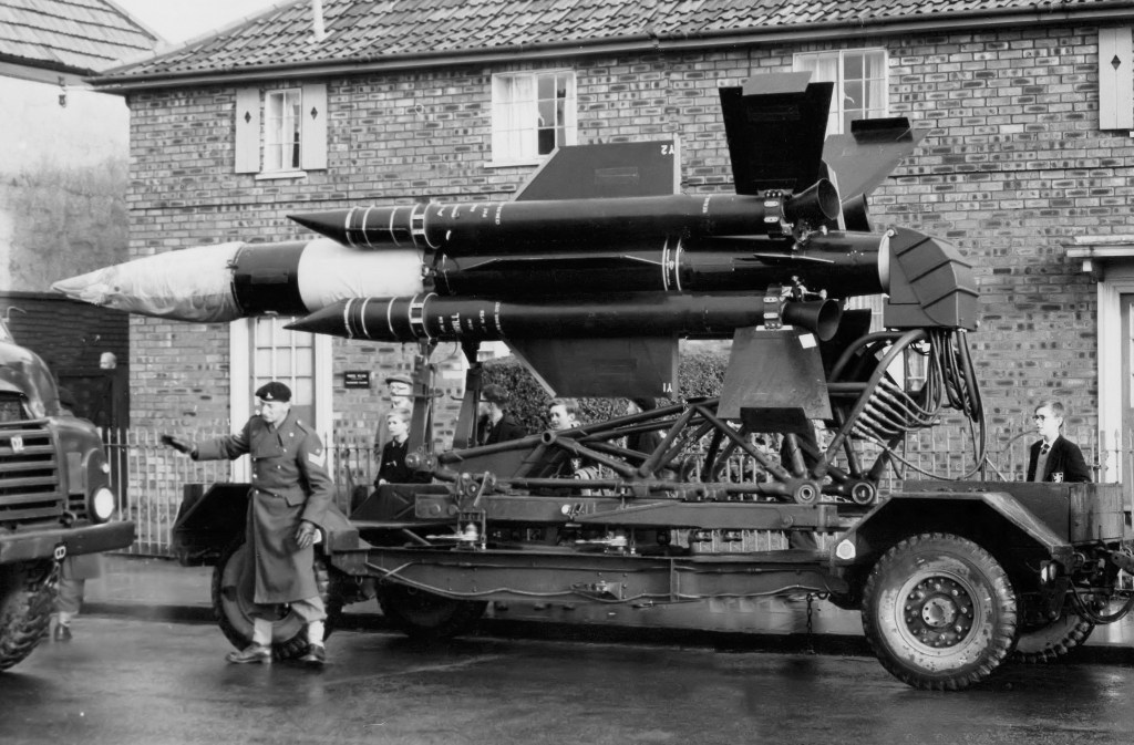
Thunderbird, c.1960 (Adrian Pingstone)
The second missile featured in the newsreel is the English Electric Thunderbird, a British Army SAM with a 75km range and a speed of Mach 2.7. The Thunderbird was replaced by the Rapier in the 70s, which is still in service today.
Hope you enjoyed seeing some of these British cold war missiles in action, it’s amazing what you find in archives when you aren’t looking for it!
Bibliography:
Footage Source: Universal Newsreel Volume 30, 1957, via US National Archives, (source) Anti-Tank Weapons, T. Gander, (2000)
If you enjoyed these videos and this article please consider supporting our work here. We have some great perks available for Patreon Supporters. You can also support us via one-time donations here.Thank you for your support!
Late last summer we visited the Anglesey Transport Museum in North Wales. They had a great collection of classic and vintage cars and bikes and most interestingly they had a little collection of British military vehicles.
They had a number of trucks and special purpose vehicles from the Royal Engineers, REME and RLC and even a Green Goddess Fire Engine. They also had a couple of pretty cool Cold War British Army armoured personnel carriers.
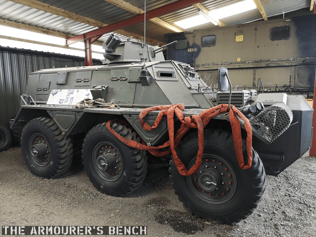
Alvis Saracen
Alvis Saracen (Matthew Moss)
The Saracen was a six-wheeled armoured personnel carrier (APC) built by Alvis. It entered service in 1952 and was used extensively in Malaya and Northern Ireland. The Saracen could carry an 8 man section along with its 2 man crew. It had a 160HP Rolls Royce engine and depending on when during its service life its turret could be mounted with a .30 calibre M1919A4 or an L37 vehicle-mounted general purpose machine gun.
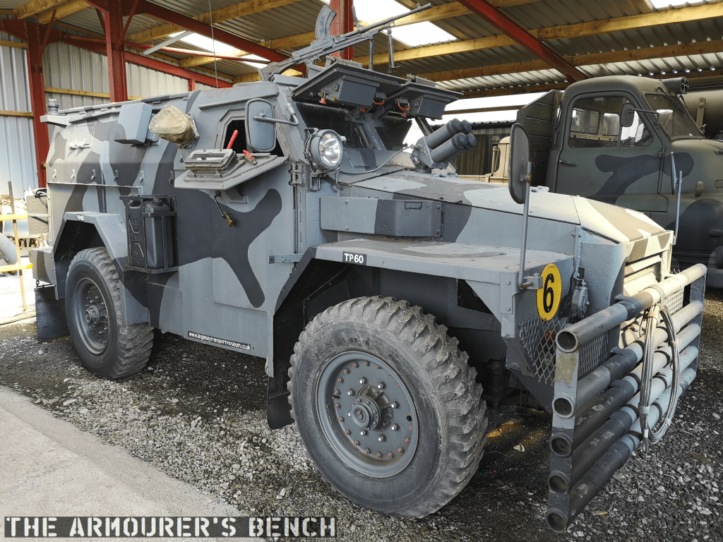
Humber Pig
Humber Pig (Matthew Moss)
Another APC which was in service alongside the Saracen, the ‘Truck, Armoured, 1 Ton, 4×4’, better known as the Humber Pig. Based on a truck chassis, it had a 120HP 6 cylinder engine and room for 6 men on the benches in the back. It could be mounted with an L4 Bren gun. It saw extensive use in Northern Ireland during operation Banner and was in service from 1956 through to the early 90s.
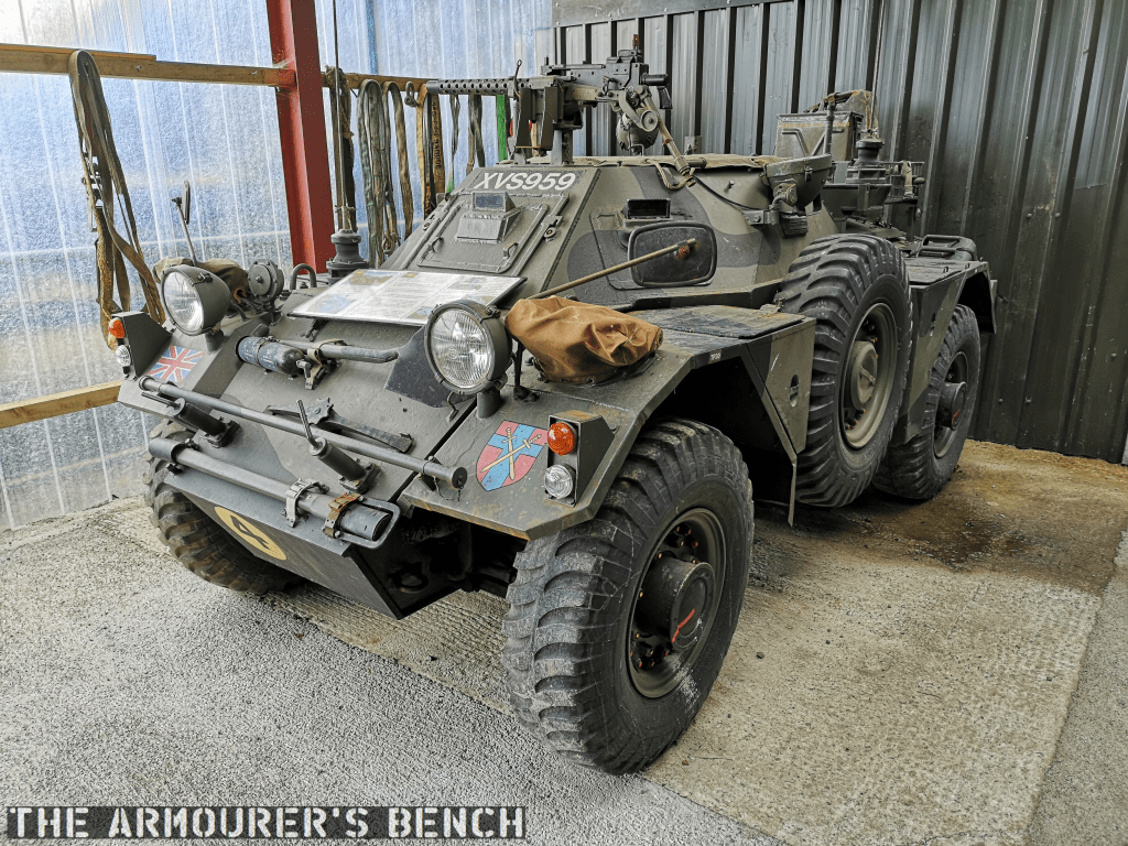
Daimler Ferret Mk1 Scout Car
Daimler Ferret (Matthew Moss)
Next to the Pig in the collection was a Mk1 Daimler Ferret scout car. Fitted out with an M1919A4 and six forward-firing grenade launchers – for smoke grenades. The later Mk2 had a turret but the Mk1 made use of its low profile. This one has its canvas cover over the fighting compartment. The 4×4 Ferret was powered by a 130HP Rolls Royce B60 straight six. Perfect little run-around to do the shopping in.
On the top of the hull is the pintle mounted Browning M1919A4 machine gun. This would have been operated by the Ferret’s commander. We can see the mount allows it to be aimed and fired from somewhat inside the hull. The Ferret entered service in the early 1950s and remained in use into the late 1980s/early 1990s. Just short of 4,500 Ferrets were manufactured.
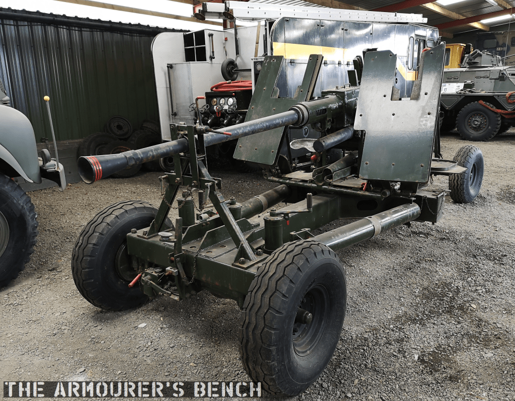
Bofors QF 40mm Mk1
QF 40mm Mk1 (Matthew Moss)
At the centre of the military vehicle collection was a QF 40mm Mk1, better known as a Bofors. Both land and naval versions of the Bofors were used during the Second World War and after. Capable of firing 120 40mm shells per minute, it was normally manned by a four man crew. It filled the British army’s light Anti-Aircraft gun role and remained in service well into the 1980s.
We can see the gun’s huge recoil spring and to the rear of the gun is a case deflector which connected with a trough which channels the spent cases down below the gun. The gun still has most of its controls and traverse and elevation crank handles in place. On top of the gun are the huge guides for the four-round clips of 40mm shells.
If you enjoyed these videos and this article please consider supporting our work here. We have some great perks available for Patreon Supporters. You can also support us via one-time donations here.Thank you for your support!