In May 1946, George Patchett patented a new curved magazine which would become one of the Sterling’s most recognisable features. It addressed some of the serious shortcomings of the STEN’s magazine.
George Patchett’s machine carbine, Which later that came to be known as the Sterling, had been initially designed to use the standard STEN magazine. This makes complete sense as not only was the STEN’s magazine readily available but it stood to reason that the British Army would prefer to retain the large number of magazines it already had in stores.
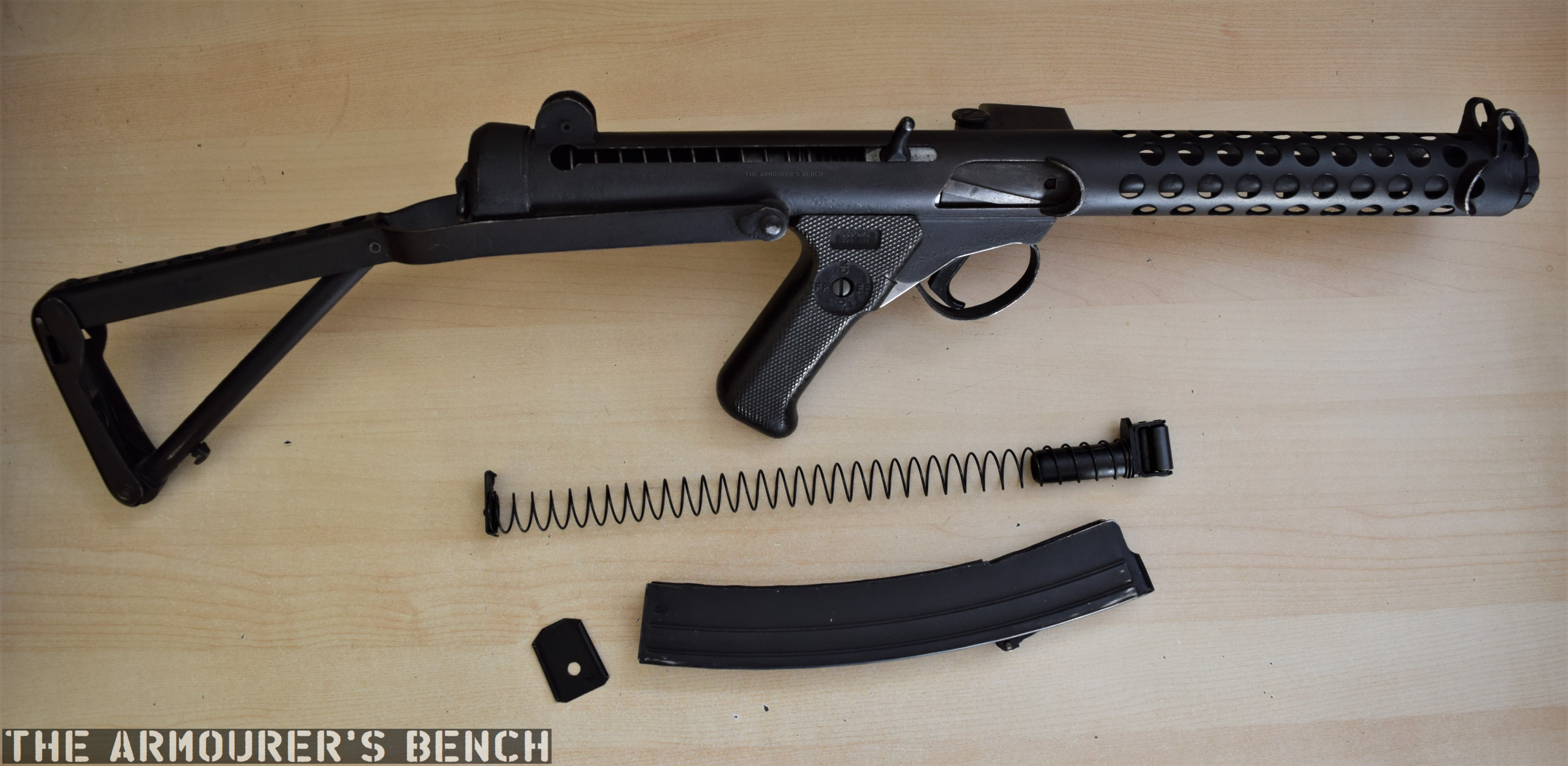
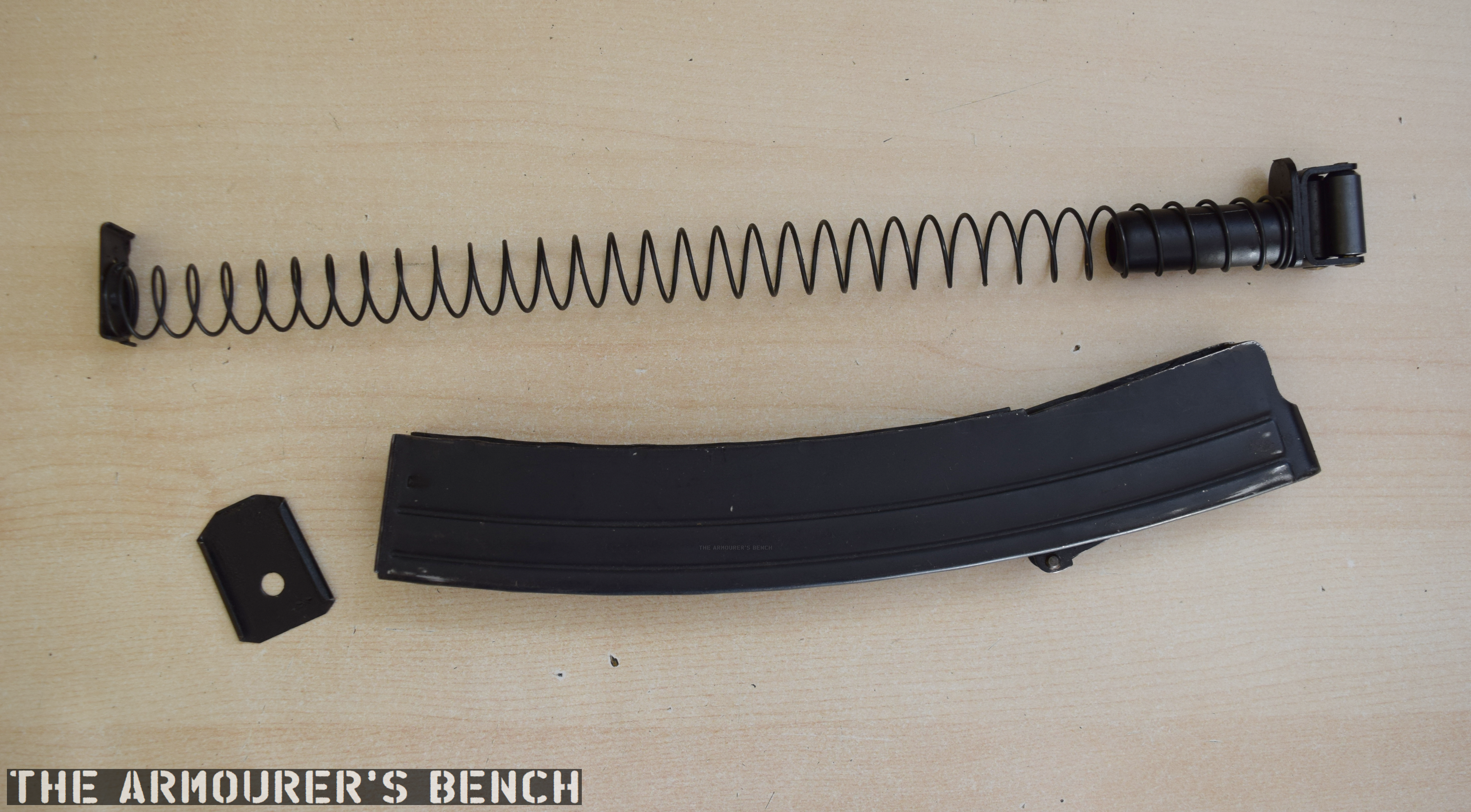
A Sterling L2A3 with a disassembled Sterling commercial-pattern magazine (Matthew Moss)
The STEN’s magazine is, however, the gun’s weakest link. Its a double-stack, single feed 32-round magazine was difficult to load and could feed unreliably when not looked after. The Patchett prototype performed well during initial testing in 1943, but later sand, mud and arctic testing of the Patchett against various other submachine guns highlighted the limitations of the STEN magazine – regardless of the weapon using it.
Patchett’s Original Toolroom prototype (Matthew Moss)
At some point in 1945, Patchett developed a series of new magazines, a 20-round ‘Patrol’ magazine, a 40-round ‘Standard’ magazine and a 60-round ‘Assault’ magazine. By late 1946, these had been superseded by a 35-round magazine designed to fit into the basic pouch of the British Army’s 1944 Pattern web equipment.
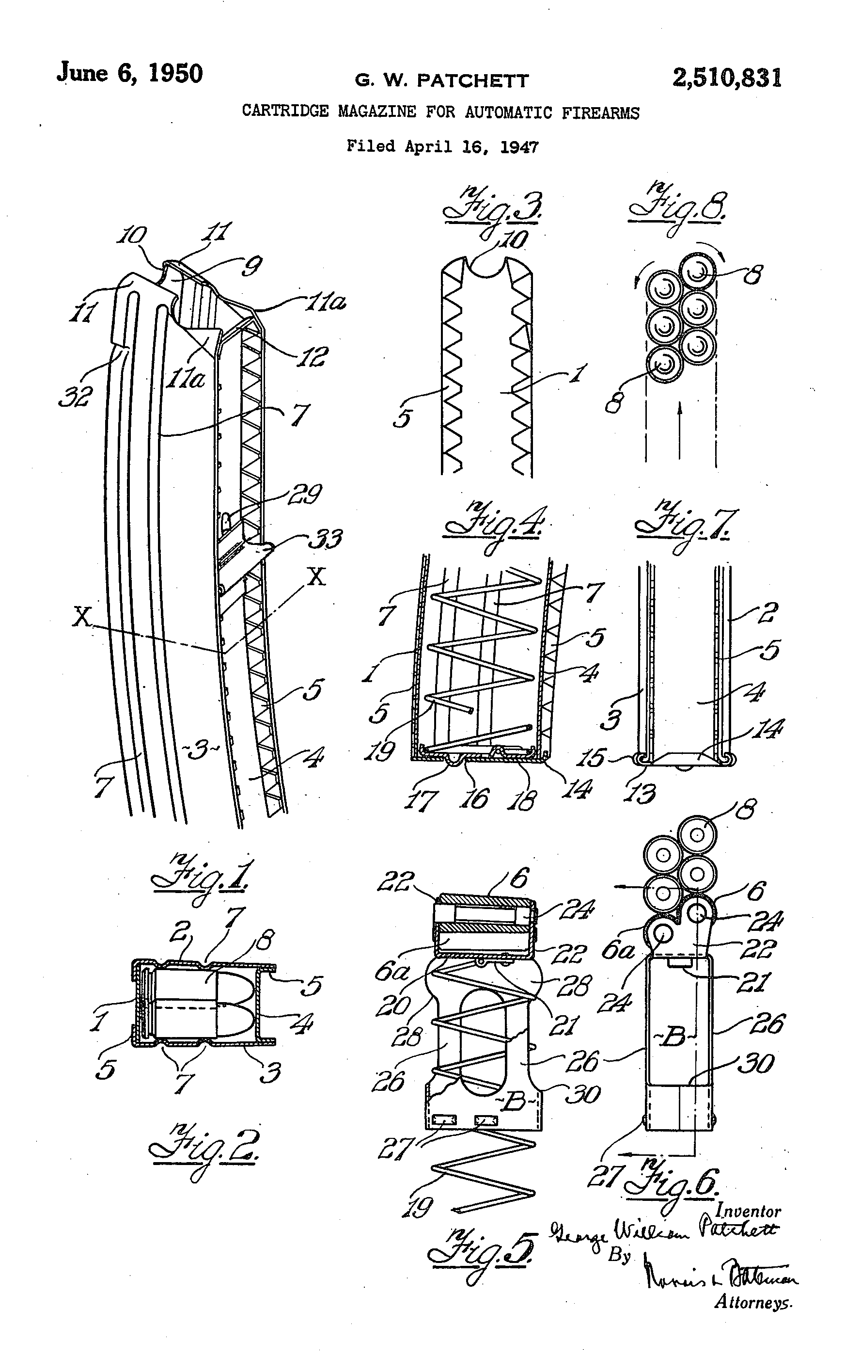
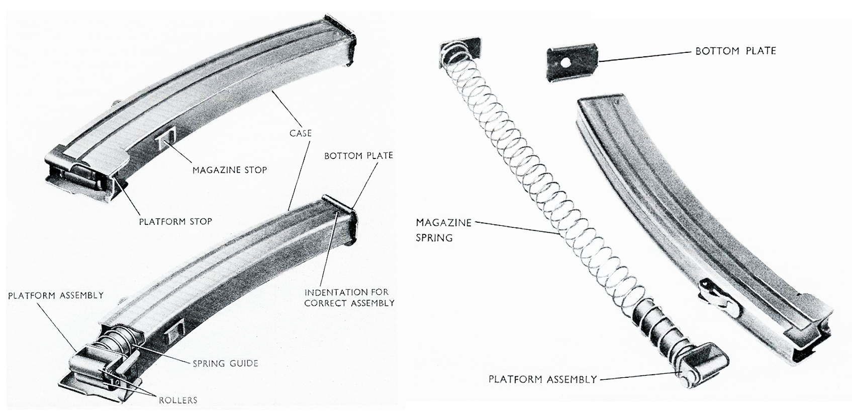
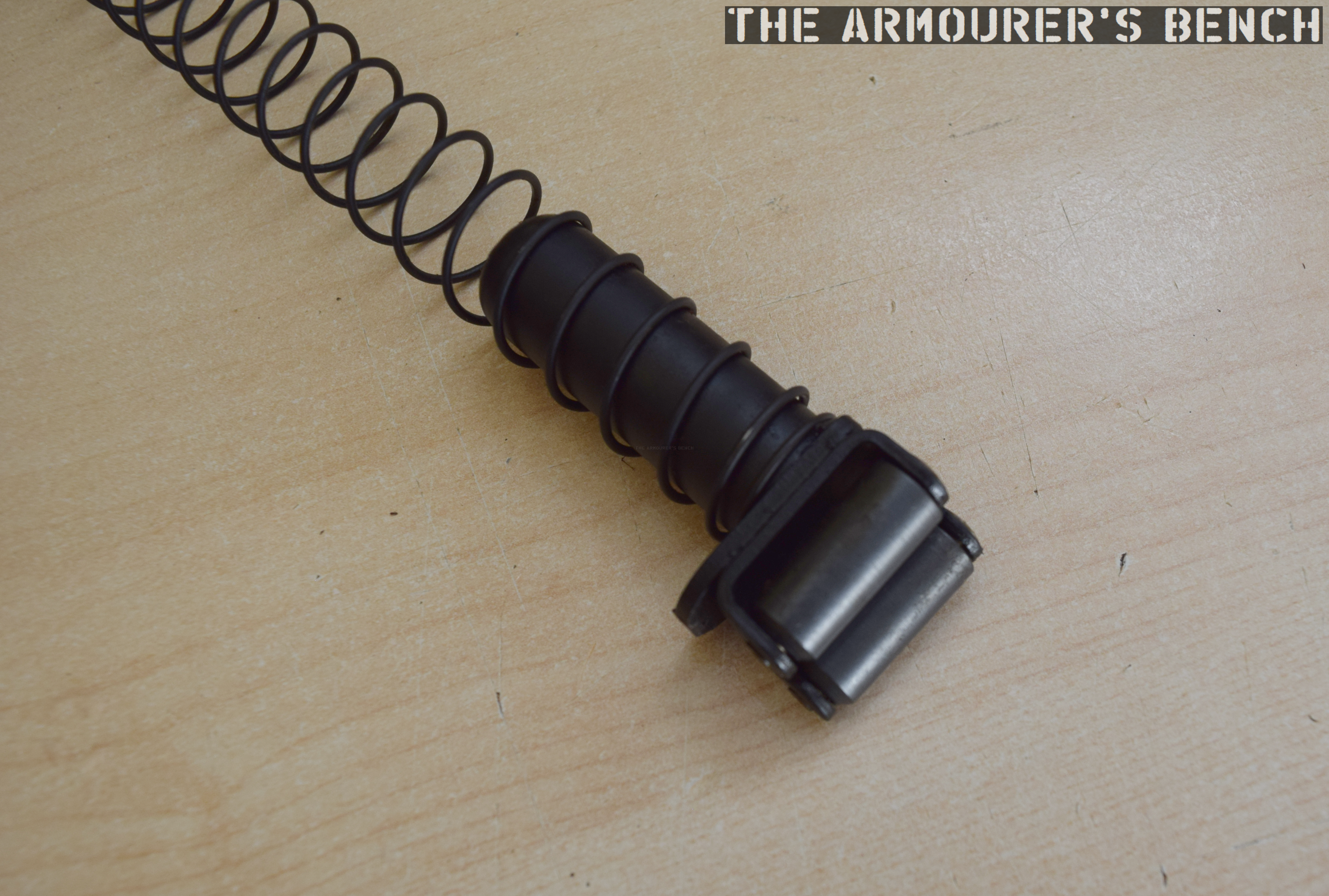
Patchett addressed the STEN magazine’s shortcomings by designing his magazine with a curve which allowed the slightly tapered 9×19mm rounds to feed more reliably. He also replaced the traditional magazine follower with a pair of rollers which minimised friction and allowed dust, grit and dirt to be rolled out of the way improving reliability. Patchett’s magazine was designed so it could be economically stamped from sheet metal and folded and spot welded into shape. It was also simple to disassemble for cleaning and requires no tools for disassembly.
George Patchett’s US patent for his roller magazine follower (US Patent Office)
By 1951 the magazine had been largely perfected but a trials report suggested that the magazine’s feed lips needed to be reinforced. Despite this the Sterling was said to be “better than all other weapons tested.” Following further development and testing the L2A1 Sterling submachine gun was eventually adopted in the summer of 1954. We will cover the development, adoption and service of the Sterling at a later date.
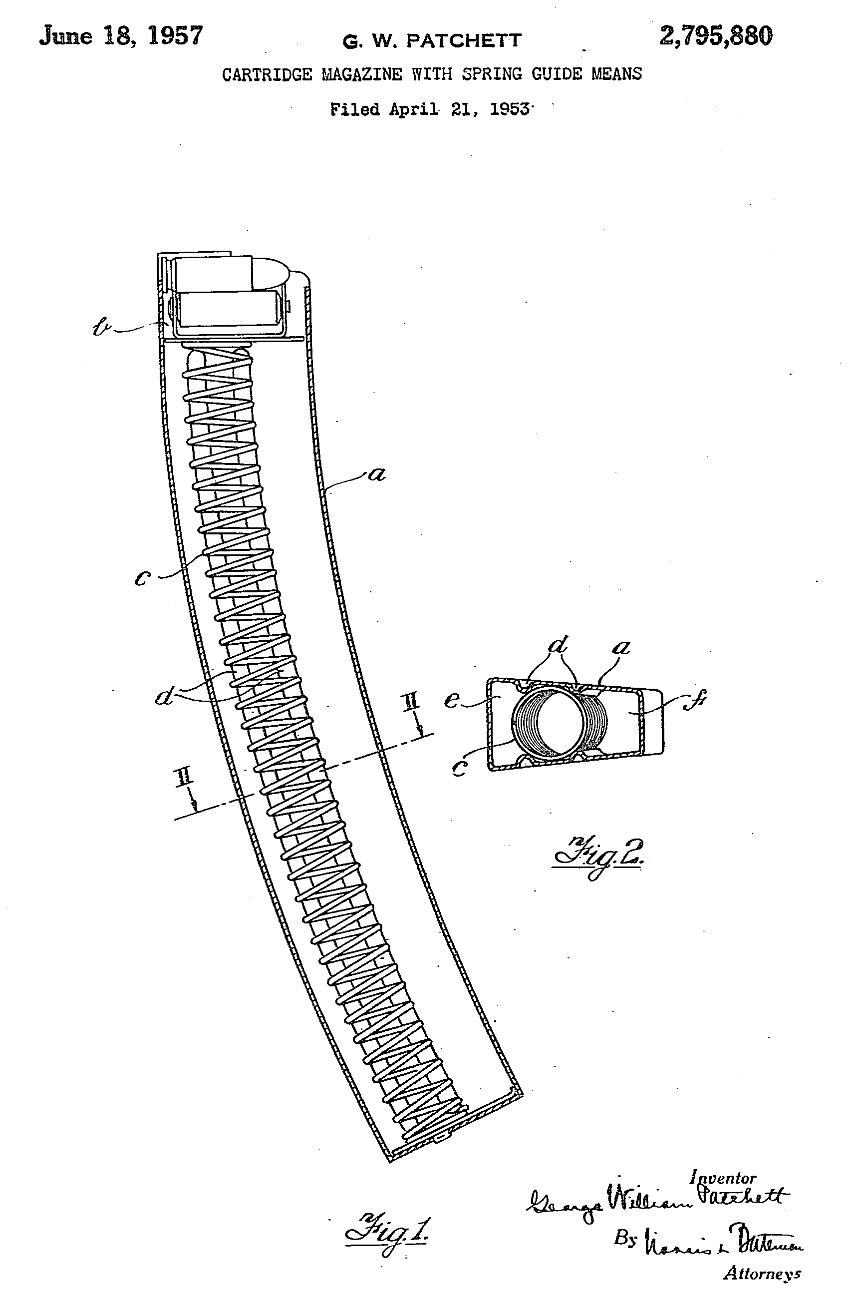
In 1952, Patchett added a pair of strengthening ribs to the inside of the magazine which also further reduced friction on the rollers. He also replaced the oval follower spring with a more efficient circular one with the ribs acting to hold it in place. The final production magazines held 34 rounds and were substantially easier to load than the earlier STEN’s.
Patchett’s US patent for his circular magazine spring held in position by the stamped magazine body (US Patent Office)
The L2A1/MkII, introduced in 1954, was the first Patchett to incorporate an angled magazine housing which improved feeding reliability from the Patchett’s patented curved, double stack, double feed magazine. The Sterling’s magazine housing was angled forward slightly at 82-degrees.
The magazines used by the British military differed from Patchett’s design. The British government, perhaps unwilling to purchase the rights to manufacture Patchett’s design, developed the ‘Magazine, L1A2’. Nearly two million of these were built at Mettoy, Rolls Razor, ROF Fazakerley and the Woolwich Royal Laboratories. The L1A2 magazine was slightly simpler to manufacture but retained Patchett’s roller follower while the magazine’s body was made from two, rather than four, pieces of stamped steel and electrically welded together. The government-designed magazine is 5cm (2 inches) longer than Sterling’s magazines.
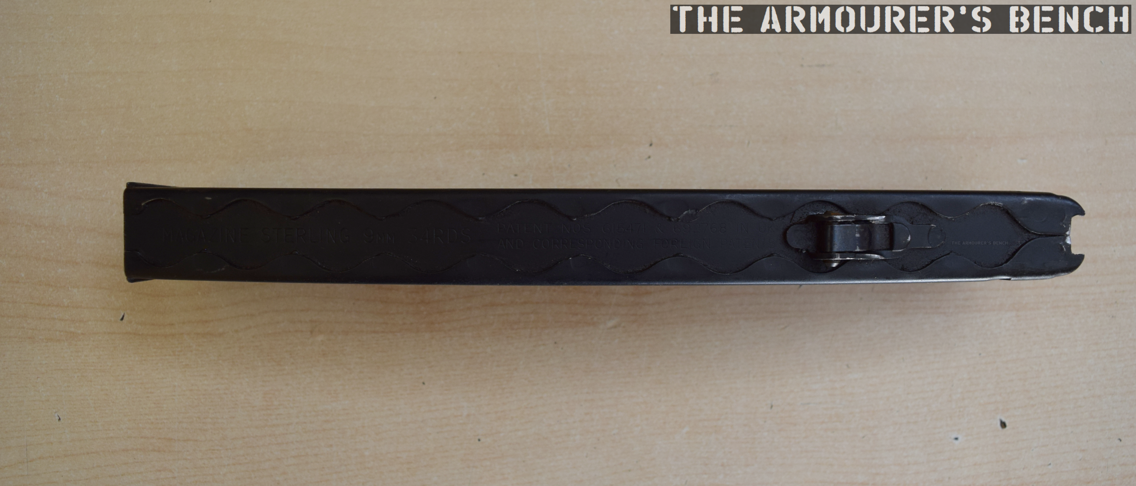
disassembled Sterling commercial-pattern magazine (Matthew Moss)Rear edge of the magazine, with Sterling factory markings (Matthew Moss)
The example magazine seen above and in the accompanying video is Sterling-made and is marked with the company name and patent numbers. We can see the folded sheet metal construction and the overlaps at the rear of the magazine body.
Patchett’s patented-roller follower and circular amazing spring (Matthew Moss)
When Canada adopted the C1, a modified version of the Sterling, they dispensed with Patchett’s roller system and designed their own magazine which held 30, rather than 34 rounds, but could be used in all Sterling-pattern guns.
On the front of the magazine is an over-insertion stop built into the edge of the magazine body, at the rear is another magazine stop with a flat spring which limits rattle and helps properly align the magazine in the breech for optimal feeding.
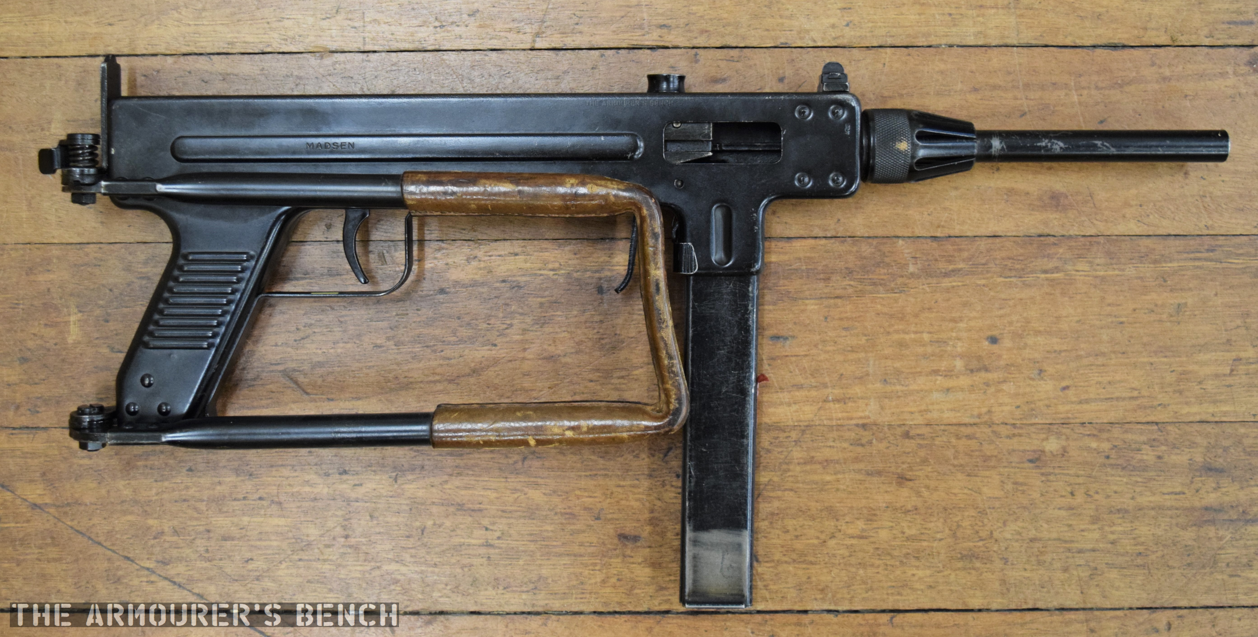
The M50 is one of the quintessential early Cold War submachine guns. Cheap, simple and utilitarian. It evolved from the earlier M46 and was developed by Dansk Industri Syndikat in Denmark. The M50 has a simple blowback action, is chambered in 9×19mm and feeds from 32-round double stack single feed magazines.
The weapon’s has a clam-shell like receiver that hinges at the rear and allows the barrel, bolt and recoil spring to be removed. The M50’s folding stock has a leather cover and while the length of pull is a little short it provides a decent cheek weld.
Madsen M50 (Matthew Moss)
The M50 has a relatively slow rate of fire of around 500 rounds per minute which makes it very easy to make single shots while in full-auto. The sights are extremely simple with a single rear peep sight.
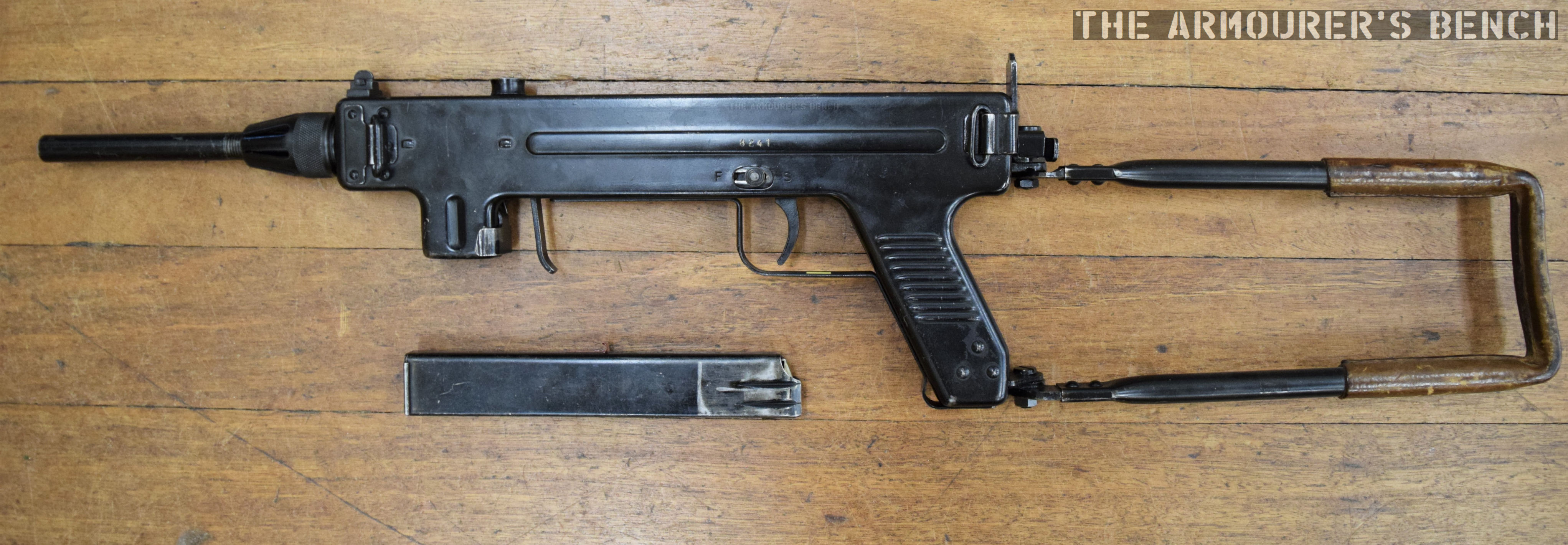
It has manual safety switch on the left side of the receiver which locks the sear in place and a spring-loaded grip safety just behind the magazine well. The amount of pressure needed to disengage it is minimal and a firm firing grip of the magazine is all that is needed.
Right side of the Madsen M50 with stock folded (Matthew Moss)
The Madsen went through a number of changes with various models having different magazine release types, selectors and manual safety positions. The M53 introduced in 1953, fed from a curved magazine and had an improved magazine release. Some models had an additional fire-selector and the safety moved back above the trigger. Some models retained the forward grip safety while others moved it to behind the pistol grip. Some patterns of M53 also had a barrel shroud for mounting a bayonet as well as added wooden panels on the pistol grip.
Left side of the Madsen M50 with stock deployed and magazine removed, not the improved magazine release (Matthew Moss)
We’ll have a more in-depth look at the Madsen M50 in the future looking at the various models in some more detail.
Special thanks to my friend Chuck at Gunlab for letting me take a look at his M50.
The Sten is one of Britain’s iconic Second World War Small arms. Two men are principally responsible for its development Colonel Reginal Vernon Shepherd and Mr. Harold John Turpin a pair of small arms and engineering experts with considerable experience.
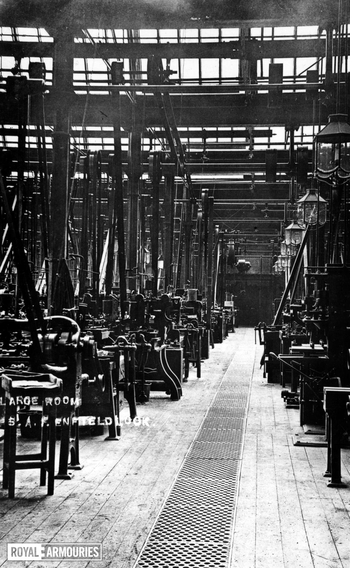
Turpin was born in Kent in 1893, served his apprenticeship as a draughtsman in Erith and in 1922, he joined the drawing office at the Royal Small Arms Factory Enfield – Britain’s principal state small arms centre.
British Army manual illustration
Reginald Shepherd was born in 1892, received an Bachelor of Science Degree from Leeds University in 1912. In October 1914, he joined the West Yorkshire Regiment as a second lieutenant, serving in Gallipoli and Egypt. After the war, with his engineering background, he assigned as 2nd Assistant Superintendent at the Design Department at RSAF Enfield in December 1922, and promoted to captain.
The two men found themselves joining Enfield at around the same time. In November 1933, Shepherd, now a major, was appointed Inspector of Small-Arms (Class 2) at Enfield and assisted in getting the Bren light machine gun into service. He remained at Enfield until 1936, when he retired from the army and spent a short spell at BSA before being recalled. In late 1939, Major Shepherd returned to active service and once again took up the position of Inspector of Armaments, this time at the Ministry of Supply Design Department at Woolwich Arsenal.
Inside RSAF Enfield (Royal Armouries)
By the outbreak of the Second World War Turpin had become the senior draughtsman at Enfield and when the development of the Lanchester Machine Carbine began he was paired with Major Shepherd to draw up technical drawings for the gun’s production.
The two men decided that a simpler, cheaper submachine gun could be produced and in December 1940 set about designing it, with Turpin in the lead. During the Winter of 1940-41 the first prototypes were built. Development of the first Sten – the T40, was completed on 8th January 1941, taking just 36 days.
14 pilot models were ordered but only two were completed by engineers at the Philco Radio Works in Middlesex: T-40/1 and T-40/2. The gun was initially designated the ‘T-40’ or Turpin, 1940. By the end of January 1941, it had become known as the ‘ST Machine Carbine’. The ‘Carbine, Machine, STEN, MkI’ was approved for issue on 7th March, 1941, with 100,000 guns ordered.
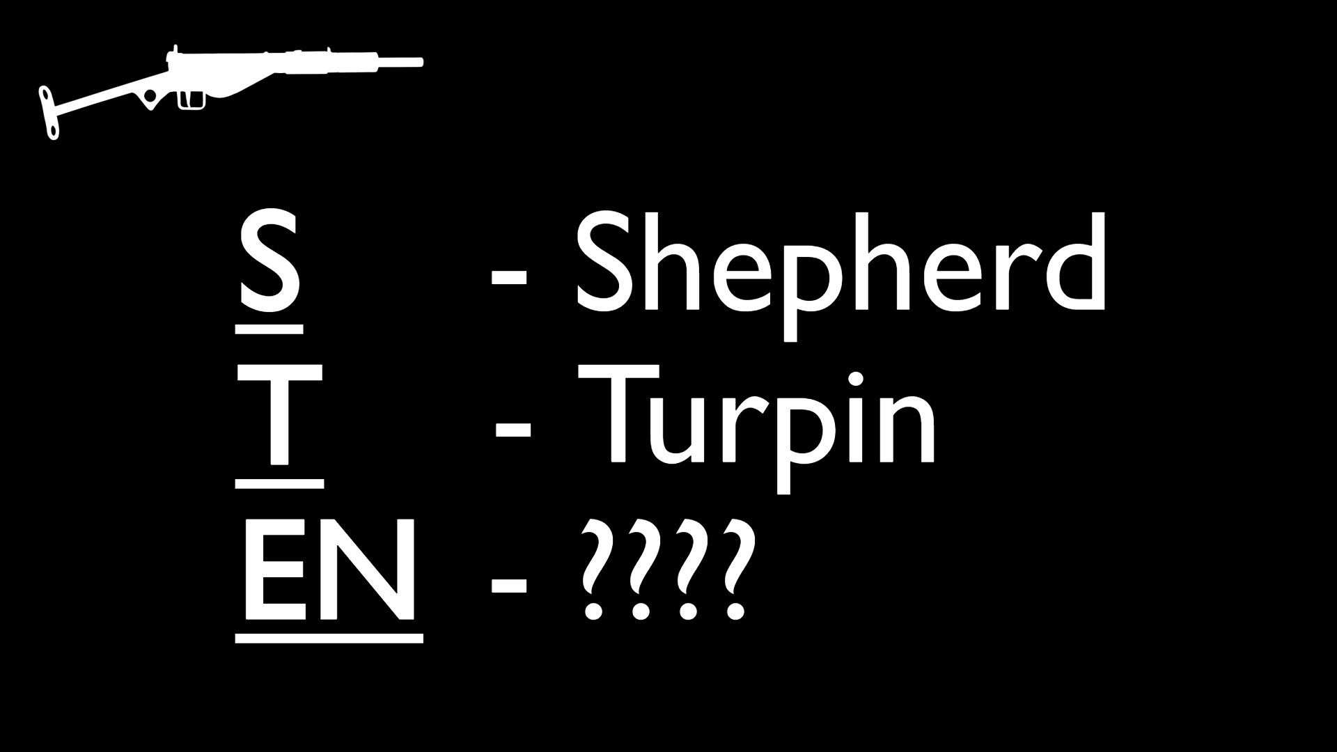
How did the gun become known as the ‘STEN’ and what did Sten stand for?
We know that the ‘S’ stands for Shepherd and the ‘T’ for Turpin, but what about the ‘EN’ – it is generally accepted to represent ‘Enfield’. Why? Because RSAF Enfield is synonymous with British military firearms. Additionally the Bren light machine gun’s name is a portmanteau of ‘BR’ from Brno, the location of the Czech factory the zb.26/30 originated from, and ‘EN’ for Enfield, the British factory that anglicised the design for British manufacture and service.
Enfield, however, wasn’t where the Sten was designed. Turpin and Shepherd claimed that most of the work on the design had been done out of hours. Additionally, during the winter of 1940, the Armament Design Department was relocated, from Enfield to a former Drill Hall in Cheshunt, Hertfordshire to escape the bombing of London.
While the Sten may not have been designed at Enfield, the first prototype was partially assembled there with work also done at Turpin’s own home workshop. A further 46 pre-production pilot models were later ordered from RSAF Enfield, in February 1941.
Intriguingly, early accounts suggest that ‘EN’ may have stood for ‘England’ – not ‘Enfield’. In October 1942, the fifth instalment of ‘Know Your Weapons’, a semi-official series of weapons manuals printed by the publisher Nicholson & Watson, explains that ‘EN’ did in fact stand for ‘England’.
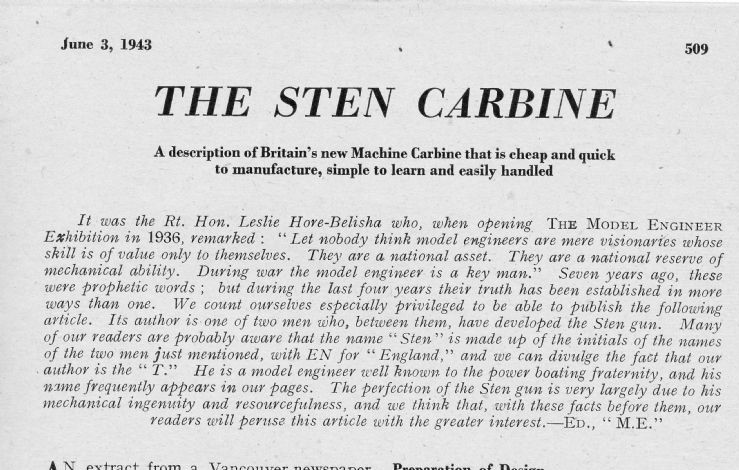
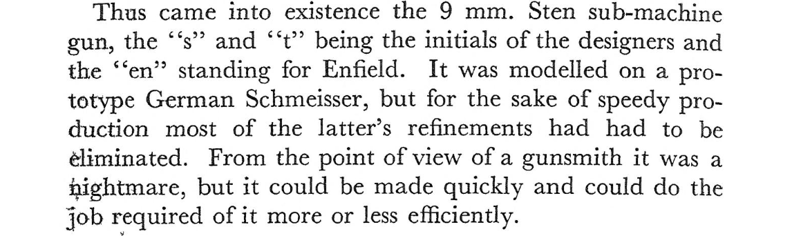
In June 1943, Turpin penned a semi-anonymous article for ‘The Model Engineer’, about the design and development of the gun, which repeated this claim. An October 1943, article in the US Popular Mechanics magazine, entitled ‘Machine Guns from Backyard’, includes a supposed quote from the inventors explaining that the “E and N stood for England.”
‘The Sten Carbine’, Model Engineer, Turpin, June 1943
A more official account came in June 1949, at a hearing of the Board of the Royal Commission Awards to Inventors (a board set up to reward inventors who had done important war work). One of the board members Lord Justice Sir Lionel Cohen asked Shepherd: “Why was it called the Sten?” The colonel replied: “It was called the Sten by the then Director General of Artillery. The ‘S’ was from my name, the ‘T’ from Mr. Turpin, who was my draughtsman and who did a very large amount of the design, and the ‘EN’ was for England. That is the origin of the name, for which I accept no responsibility.” This suggests that the ‘EN’ standing for ‘England’ may have originated from the upper echelons.
Sadly, there was no officially published explanation of the name as official manuals rarely go into superfluous detail. In 1948, however, Ian Hay published R.O.F. The story of the Royal Ordnance Factories, 1939-1948 in which he stated the ‘EN’ was a reference to the Enfield factory. Similarly, another early published account, D.M. Ward’s 1946 The Other Battle, a history of BSA, also suggested it represented the factory name.
In truth it is difficult to know exactly what the ‘EN’ stood for. It may be that both Enfield and England were discussed and used by various individuals and offices. There may have been an element of propaganda to including ‘England’ in a weapon’s name which led senior officers to push this in the press and direct the gun’s inventors to suggest this was the case too. Of course the authors of those earlier books may have mistakenly believed ‘EN’ stood for Enfield, as it does in Bren. Personally, I’m inclined to follow the primary sources attributed to the two men responsible for the design, and believe it initially stood for England.
The Other Battle, D.M. Ward, (1946)
Shepherd was awarded an OBE in January 1942, and became the Assistant Chief Engineer Armament Design (A/CEAD), he was promoted to Lt. Colonel in August 1943. He retired from active duty at the age of 55, in January 1947, and was removed from the reserve list. He was granted the honourary rank of colonel. He died in April 1950, aged 58. Turpin retired from RSAF Enfield in 1953, and died in April 1967, aged 74.
Beyond a pair of discretionary payments, £1,500 to Shepherd and a small payment of £200 to Turpin, neither man was officially rewarded as they were deemed to have essentially done what they were paid for, designing small arms. Scant reward and recognition for a weapon which became one of the key wartime small arms of the British and Commonwealth forces.
Our thanks also to Jonathan Ferguson, of the Royal Armouries, for sharing his thoughts on the ‘Enfield’ vs ‘England’ debate.
Bibliography
The Sten Machine Carbine, P. Laidler, (2000) R.O.F. – The Story of the Royal Ordnance Factories, 1939-1948, I. Hay, (1949) The Other Battle, D.M. Ward, (1946) The Sterling Submachine Gun, M.J. Moss, (2018) The Sten Gun, L. Thompson, (2012)
‘Sten & Bren Guns’, Know Your Weapon #5, (Oct. 1942)
‘The Sten Carbine’, Model Engineer, 3 Jun. 1943, H.J. Turpin Board of the Royal Commission Awards to Inventors – 1946-49
‘Machine Guns From Backyard’, Popular Mechanics, Oct. 1943
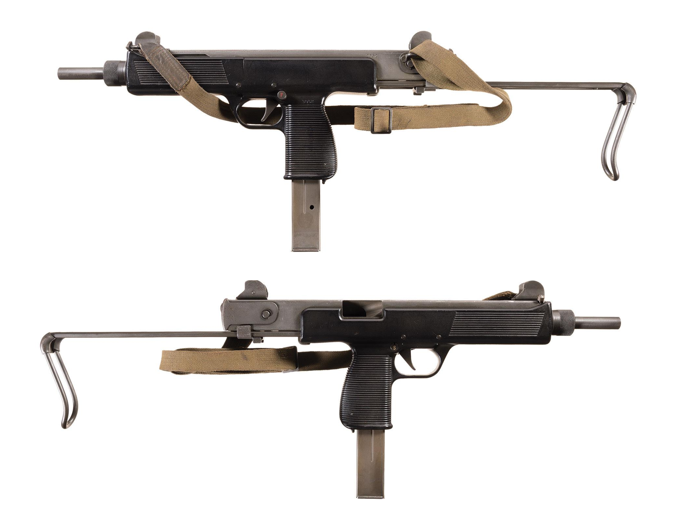
Developed in the late 1960s and introduced in 1969/70 the MPi 69 was Steyr’s entry into an already crowded European submachine gun market. Heavily influenced by the Israeli Uzi it had a bolt which telescoped over the barrel and fed from a box magazine that was inserted through a magazine well-come-pistol grip.
The MPi 69 weighed 6.5lbs (2.93kg) unloaded and had a polymer lower receiver into which a stamped metal upper inserted. Unlike the Uzi it had a collapsing, rather than folding stock, similar to the M3 submachine gun’s, and was cocked not by a handle but by pulling the sling (which was acted on the bolt) to the rear.
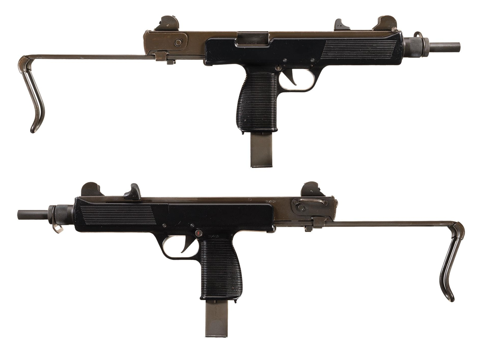
Steyr MPi 69 (Rock Island Auction Company)
The MPi 69 remained in production into the early 1980s when it was replaced by the improved MPi 81. Moving away from the slick-cocking ‘gimmick’ the MPi 81 had a conventional, non-reciprocating, charging handle on the left side of the receiver. The MPi’s polymer lower allows it to be a pound lighter despite being slightly longer as a result it also balances better than the standard Uzi carbine.
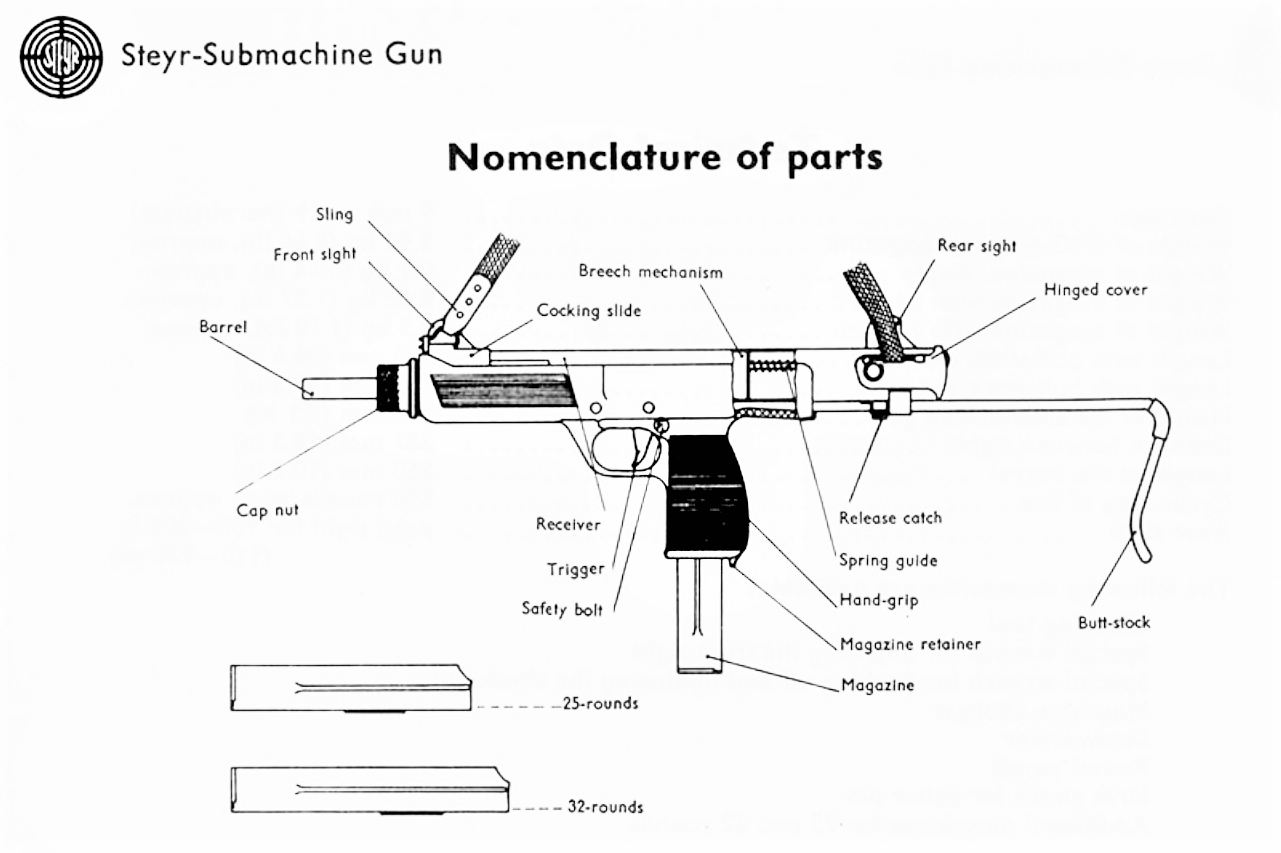
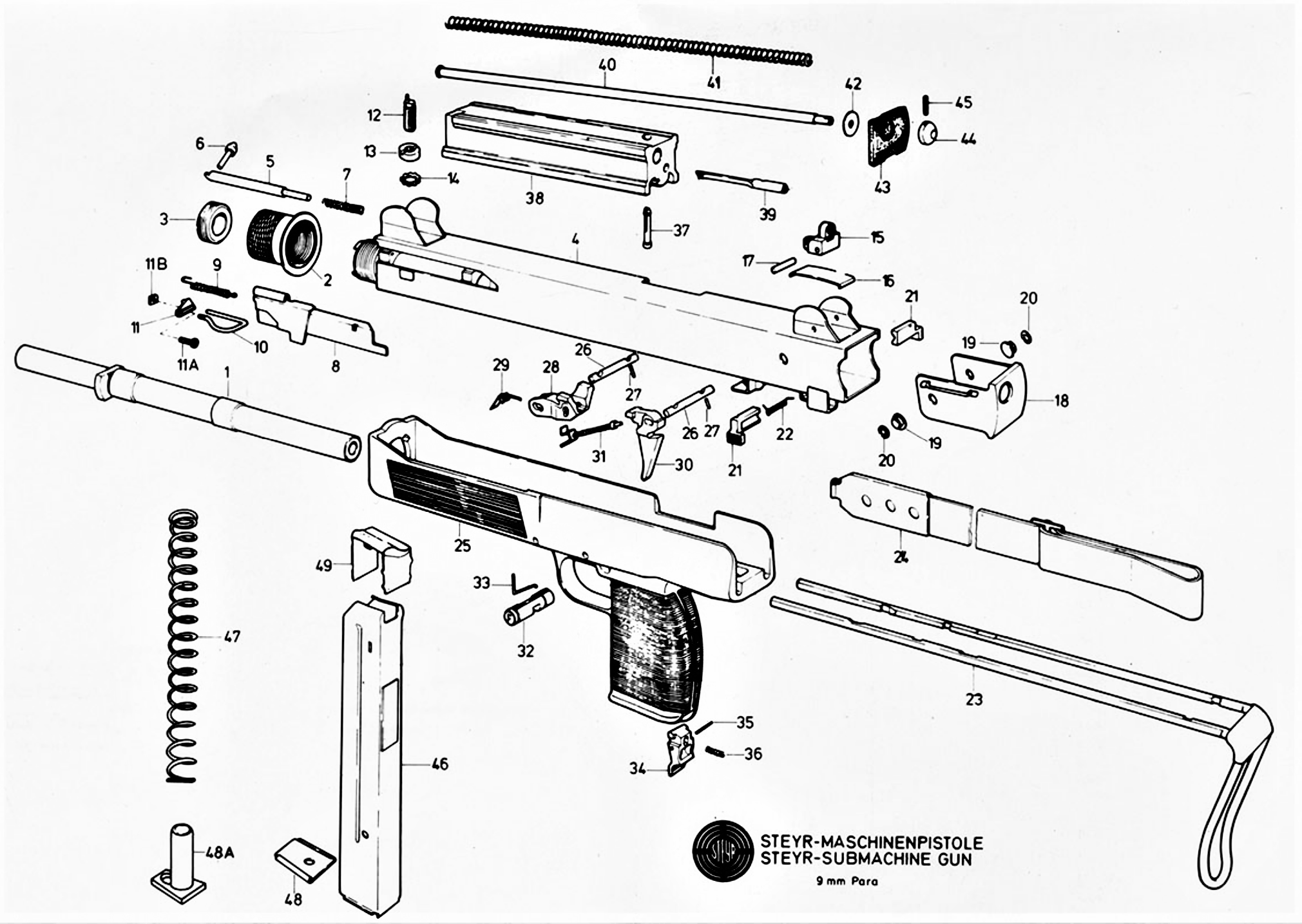
Steyr MPi 69 diagram (Steyr Manual)
The MPi submachine guns fed from 25 or 32 round box magazines and both guns had a heel-type magazine release paddle in the base of the pistol grip. They also shared their magazines with the AUG 9x19mm submachine gun conversion. Check out our earlier video on the Steyr AUG conversion here.
Steyr MPi 81 (Rock Island Auction Company)
The MPi submachine guns fire from an open bolt and had a 10in barrel and has a push through safety with settings for safe, semi and full auto and unlike the Uzi it does not have a grip safety – simplifying manufacture.
The MPi also has a progressive trigger which when set to full-auto will allow the user to fire semi when pulled to the first stage and full when pulled fully to the rear. While the MPi 69 had a cyclic rate of around 500 per minute, the MPi 81 increased this rate to ~750rpm.
Steyr MPi 69 disassembly diagram (Steyr Manual)
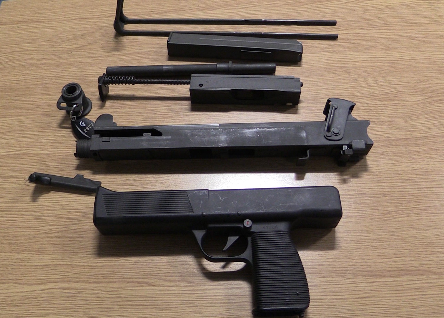
The MPi can be field stripped by simply rotating the receiver end cap up 90-degrees and pulling the bolt out the rear. The gun can be further stripped but the moulded polymer lower receiver can be difficult to remove from the upper. Like the Uzi the barrel nut is unscrewed to remove the barrel.
The MPi 81 fully disassembled (Vic Tuff)
It is unclear just how many MPi submachine guns were produced but they didn’t see any significant contracts beyond a few small sales to police forces and militaries.
The MPi 81 remained in production into the early 1990s when it was replaced by the smaller and more compact Steyr TMP in 1992. In turn the TMP design was sold to B&T a decade later.
Our thanks to the collection that let us take a look at this MPi 81 and to our friend Miles Vining for sharing some of his shooting footage of the MPi 81 with us, check out his video here and more of his work at www.silahreport.com.
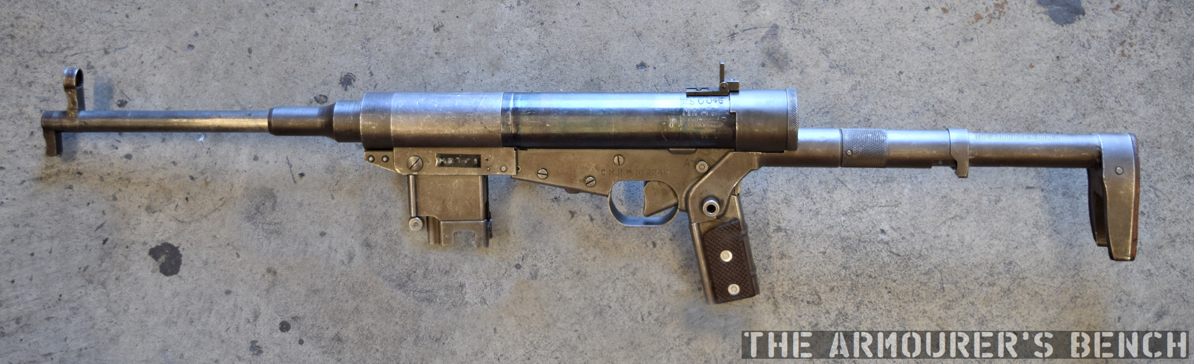
Here’s a short video looking at how the unusual Hotchkiss Universel deploys from its compact, folded position. The whole process takes just seconds. Impressive engineering but within a couple of years the Universel would be surpassed by far more compact, ergonomic and serviceable designs like the Uzi and PM-63.
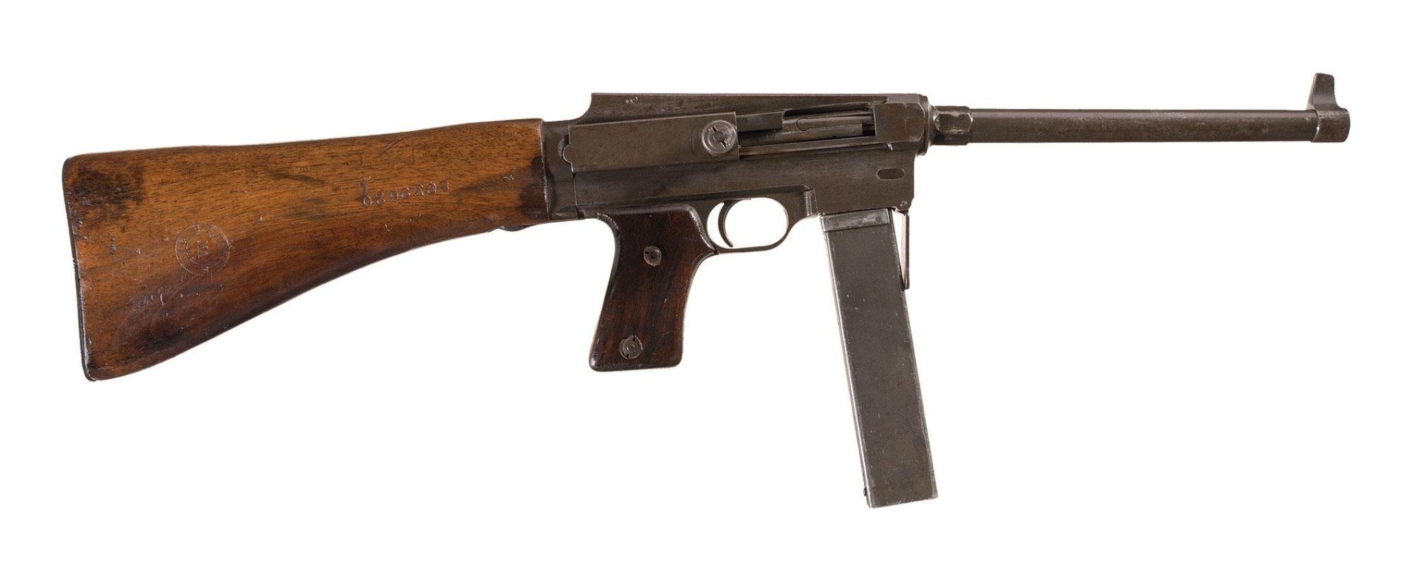
The need for compact weapons capable of being carried with ease by troops who would be getting in and out of vehicles, jumping from planes and fighting in close quarters had been proven during World War Two. While it may look unusual the Hotchkiss ‘Type Universel’ was an extraordinary attempt at creating an extremely compact submachine gun.
Right-side Hotchkiss Type Universel (Matthew Moss)
Submachine guns had proven themselves to be an useful weapon during the war, their small size and high rate of fire made them invaluable, especially in close-quarter situations. The post-war French army found itself armed with a plethora of surplus submachine guns, which included: the German MP40, the British STEN and the American Thompson as well as their own pre-war MAS-38s, in 7.65x20mm Longue, which had been designed before the war. By 1946 they had already begun the process of selecting a new, more compact submachine gun. Seeking to standardise on a single weapon and calibre they selected 9x19mm and launched a programme to find a new submachine gun or Pistolet Mitrailleur.
MAS-38 (Rock Island Auction Company)
The French War Ministry launched a call for state arsenals and civilian manufacturers, such a Hotchkiss and Gevelot/Gevarm, to submit submachine guns for trials. Hotchkiss submitted the Type 010 or Type Universel, often anglicised as Universal, despite this the guns are typically marked ‘CMH2’ – ‘Carabine Mitrailleuse Hotchkiss’.
Chambered in 9x19mm, the Hotchkiss fed from MP40-pattern magazines, used the ubiquitous blowback action, it fired from a closed bolt and had a cyclic rate of approximately 650-rounds per minute. The Hotchkiss is select fire with a push through selector that allows for semi and full-auto fire. It appears that the weapon’s only safety mechanism is to close the ejection port cover and lock the bolt in place – much like a US M3 Grease Gun.
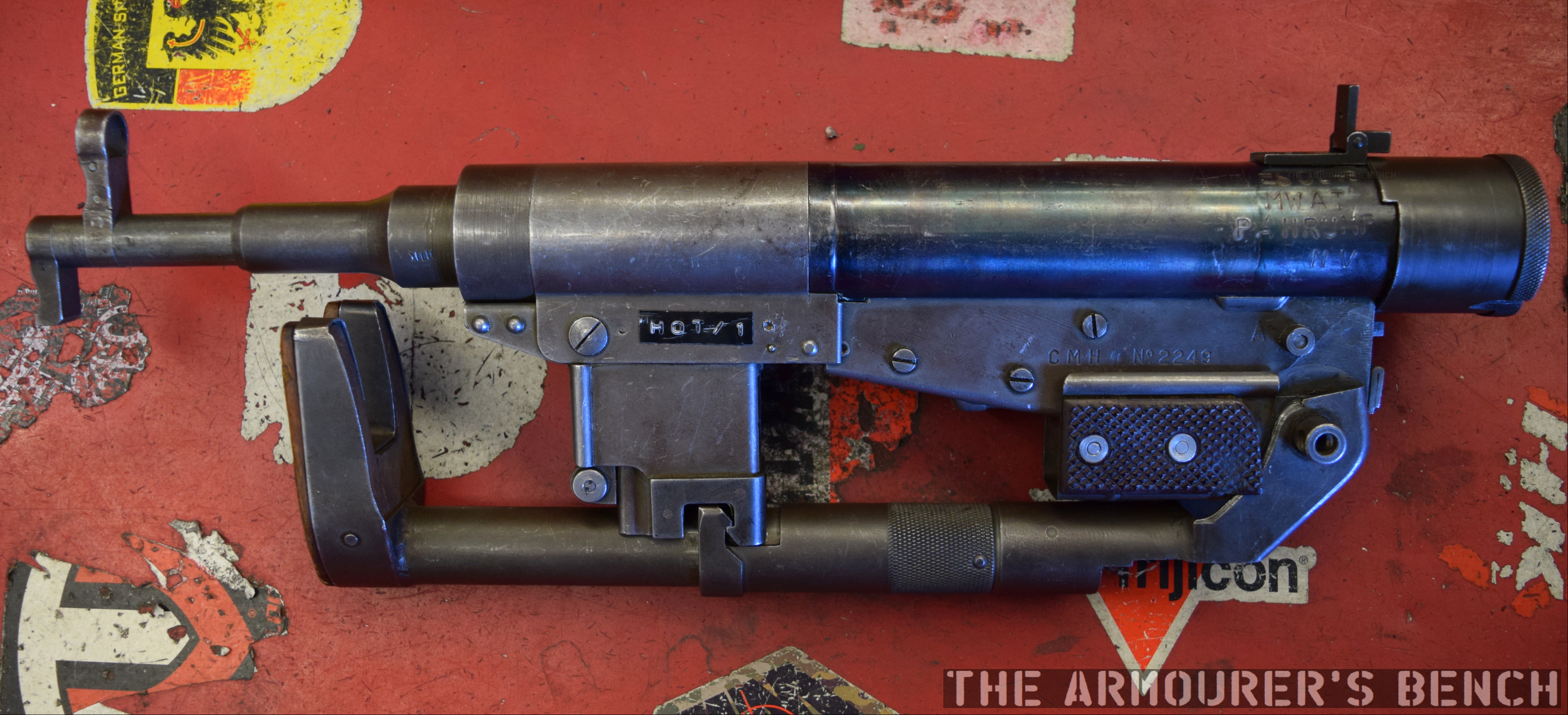
Right side collapsed Hotchkiss Type Universel (Matthew Moss)
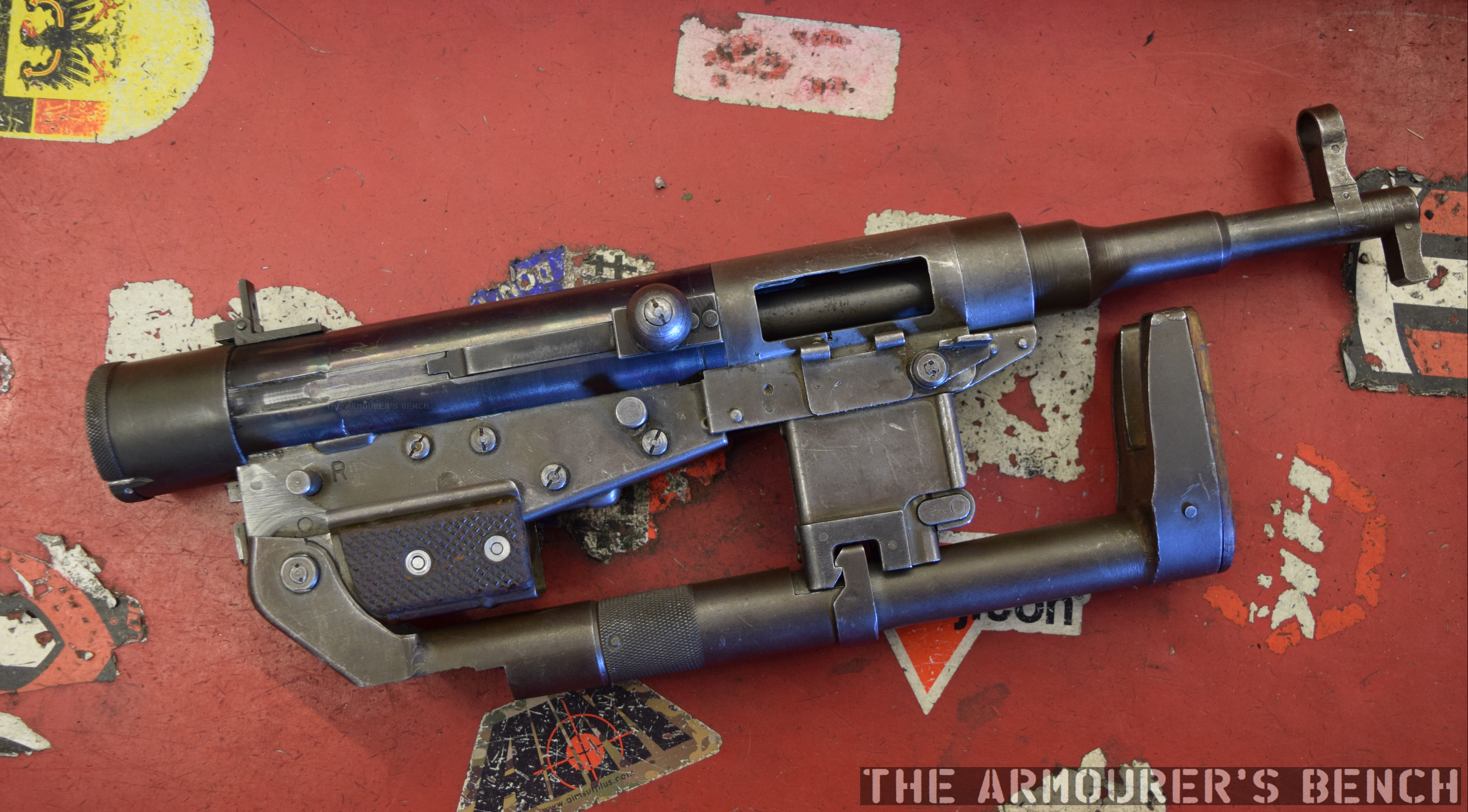
Designers went to extraordinary lengths to minimise the size of the Universel. Not only did the stock fold beneath the barrel but the magazine well and magazine could be rotated forward to sit beneath the barrel with the magazine fitting between a U-shaped cut-out in the butt stock. The weapon is a curious mix of stamped metal and complex machining with a difficult to machine bolt and barrel contrasting with a stamped sheet metal lower receiver and wide stamped trigger.
Left side collapsed Hotchkiss Type Universel (Matthew Moss)
In 1950 Hotchkiss sales material described their weapon as “the individual defense weapon meeting the requirements of the most modern Armies and Police. Folded up, it is very compact, easy to transport, conceal and parachute. It is quick to set up and comes unfolded in the form of a carabiner…”
The weapon’s pistol grip was hollow and when folding up the stock, the grip folds forward to cover the trigger. The Universel’s most interesting feature is its telescoping barrel which retracts several inches inside the receiver. These features brought the Hotchkiss’ length down from 30.6 inches (77.6cm) when the stock was extended, to 22 inches (54cm) with the stock folded, and an impressive 17.25 inches (43.5cm) when fully collapsed. The nature of how the pistol grip folded with the stock meant the weapon could not be fired with its stock collapsed. When fully collapsed the weapons’ depth was just 6 inches or 15.3cm.
A partially collapsed Hotchkiss, with magazine in folded position and barrel extended (Royal Armouries)
To Deploy:
First we unfold the stock by pushing the knurled collar forward to unhook it from the base of the magazine well. When fully unfolded a spring detent locks into the rear of the receiver.
At the same time the pistol grip also unfolds. If we had a magazine loaded into the weapon we would deploy the barrel first – in order to allow the magazine to slide back through the magazine well and fold down to lock into position. The bolt follows the barrel forward so once the magazine is locked into position the weapon has to he be charged to chamber a round.
The collapse the weapon again, first fold the stock, then depress the lever just behind the trunnion to unlock the barrel, push the barrel assembly and bolt to the rear until it locks.
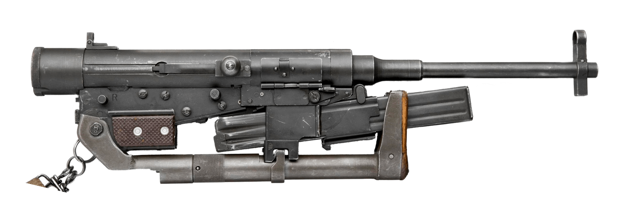
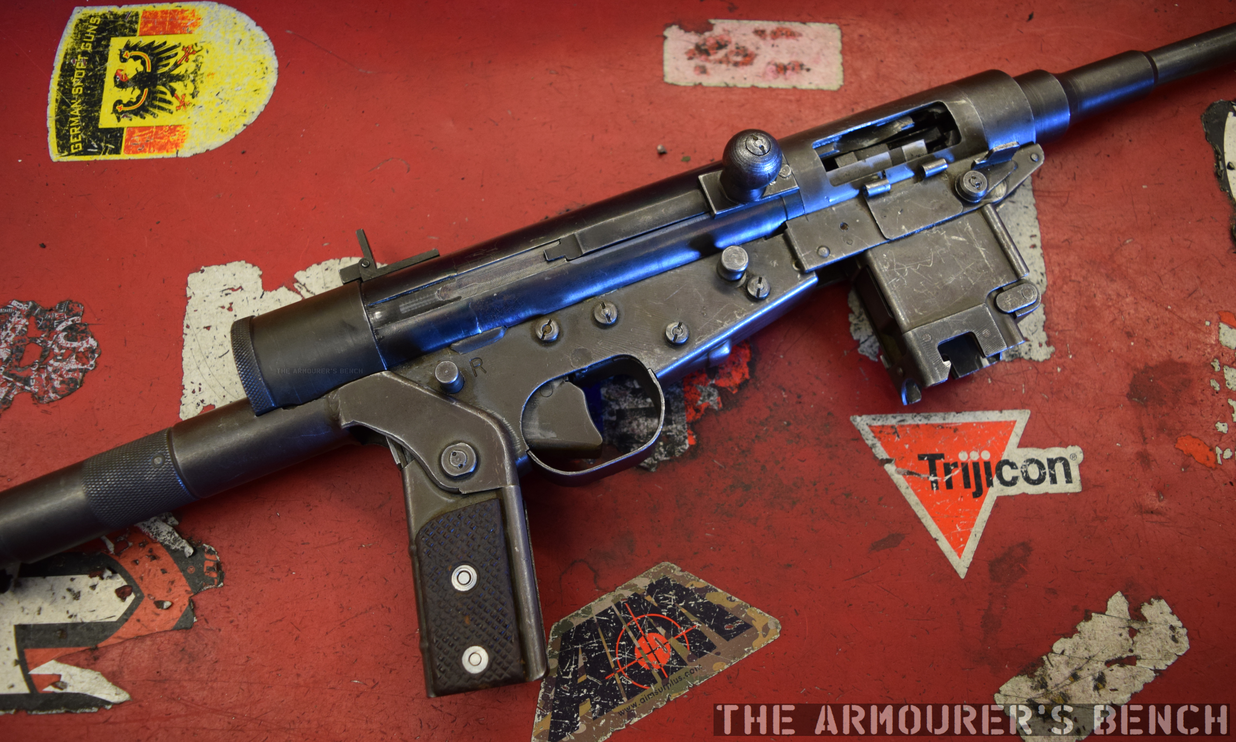
Left side Hotchkiss Type Universel (Matthew Moss)
The Universel’s extreme compactness was both its best and worst feature, the complexity of having every protruding part fold or retract made the weapon expensive to produce. It also gave the weapon poor ergonomics with a narrow butt, an uncomfortable pistol grip and narrow sights which weren’t ideal for quick target acquisition.
The Hotchkiss was one of a whole host of compact folding submachine guns developed after World War Two. These included the MAS MLE 1948, the MAC Mle 1947 and of course the MAT-49 from French state-arsenals. The French guns were by no means the first to have folding magazines, that concept dates back to submachine guns like the SIG MKMO. Incidentally, SIG’s last developmental iteration of their submachine guns, the MP48, was also developed in the late 1940s and retained the MKMO’s folding magazine housing.
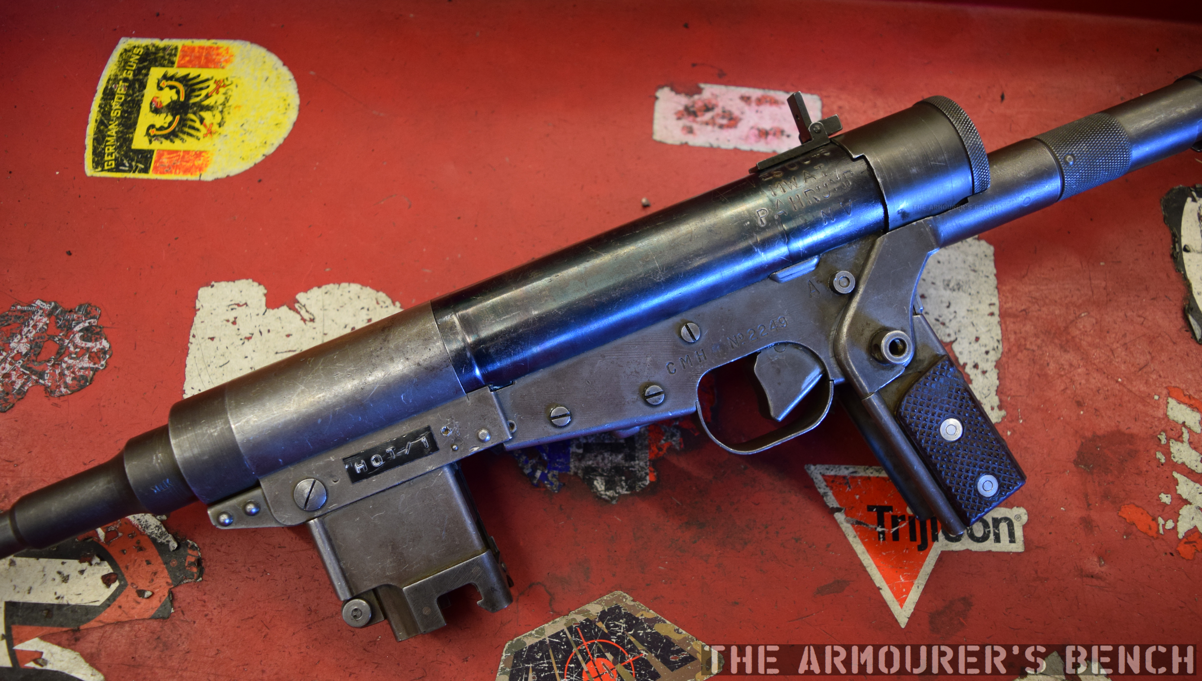
Close up of the Hotchkiss Type Universel’s receiver (Matthew Moss)
A 2001 article from the Gazette des Armes, by Michel Malberbe, includes an account from a Legionnaire sergeant who describes using the Hotchkiss in Indochina:
“I saw for the first time the submachine gun Hotchkiss in ‘Indo’. We were responsible for the security of the RC4 [Route Coloniale 4], and the staff sent us wooden cases containing these famous submachine guns. As the documents were not very complete, our company commander… had trouble explaining how it worked. It was quite funny, because folded, this submachine gun did not look very serious. It was like a rectangular scrap metal package… We used it for the first time on the Lang Son side, during a serious collision between the Viets and a convoy… I remember that this machine worked very well. But it lacked a little precision. Anyway, it was much better than the small MAS-38 submachine gun, whose magazine always blocked [jammed] at the wrong time! On the other hand, I think I remember that the Hotchkiss did not stand up to mud and that it was misery to clean it. In addition it was quite difficult to unfold because of the buttons found everywhere. We never knew which one to press. We, in any case, always transported them in the firing position…”
While the Type Universel definitely wouldn’t win any prizes for its aesthetics, it was a ambitiously-engineered and well-built submachine gun. Despite this the design was simply too complex, as we have heard troops in the field rarely took advantage of its compact features preferring to carry the weapon at the ready. The Universel sacrificed a lot to achieve its compactness and the ergonomics of the weapon leave a lot to be desired with an extremely small butt and a hollow pistol grip that just feels wrong.
It is believed that in total just 7,000 Hotchkiss Universels were produced between 1948 and 1952. The French military rejected the Hotchkiss feeling the weapons was too complex and too expensive to manufacture. Instead, the MAT-49 submachine gun, designed by Tulle, was eventually adopted. The MAT-49 also had a folding magazine housing making it almost as compact as the Universel but without its complexities.
Close up of right side of the Hotchkiss Type Universel’s receiver (Matthew Moss)
While it underwent some field testing with the French in Indochina no major military contracts were won but small numbers were purchased by the French police, the colonial police in Morocco and some were sold to the military of Venezuela. The Universel would be one of the last firearms produced by Hotchkiss et Cie, who had built numerous armaments for the French army during the 19th and 20th centuries, before it closed its weapons manufacturing arm in the early 1950s refocusing on automobile manufacture.
Special thanks to Battlefield Vegas for allowing us to take a look at their Hotchkiss.
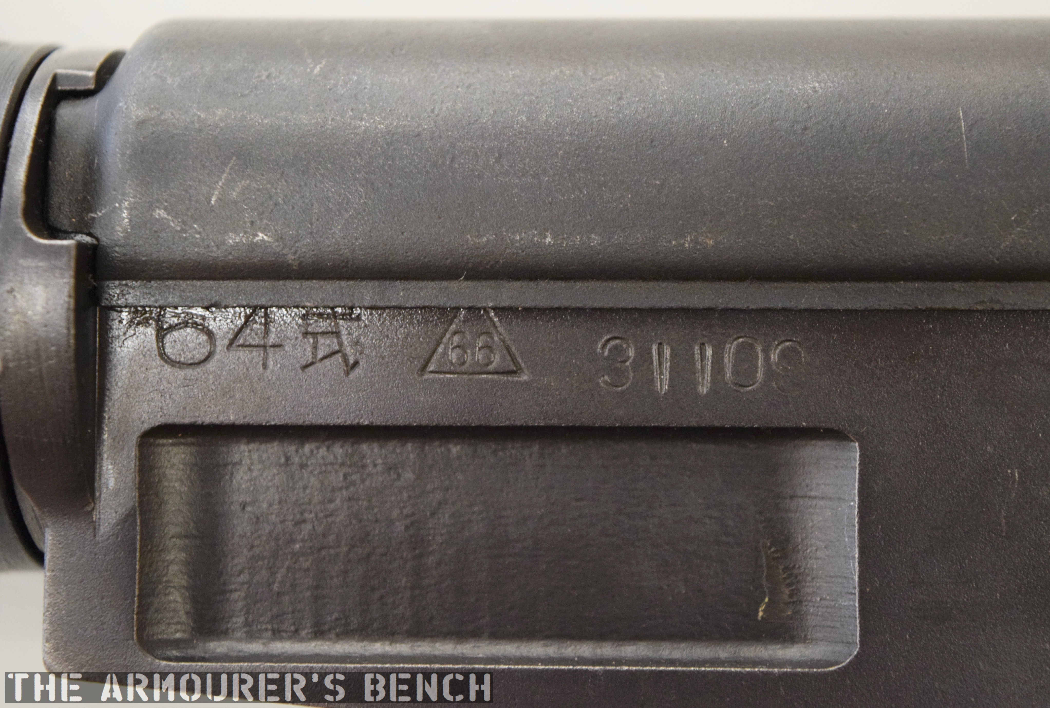
The Type 64 is an integrally suppressed submachine gun designed in China in the early 1960s, taking several design elements from other Combloc small arms. The guns were manufactured at one of China’s State Factories (with the factory’s ‘66’ in a triangle marking in the left side of the receiver – this indicates the factory number, although available sources differ on which it refers to, either 66, 626 or 366).
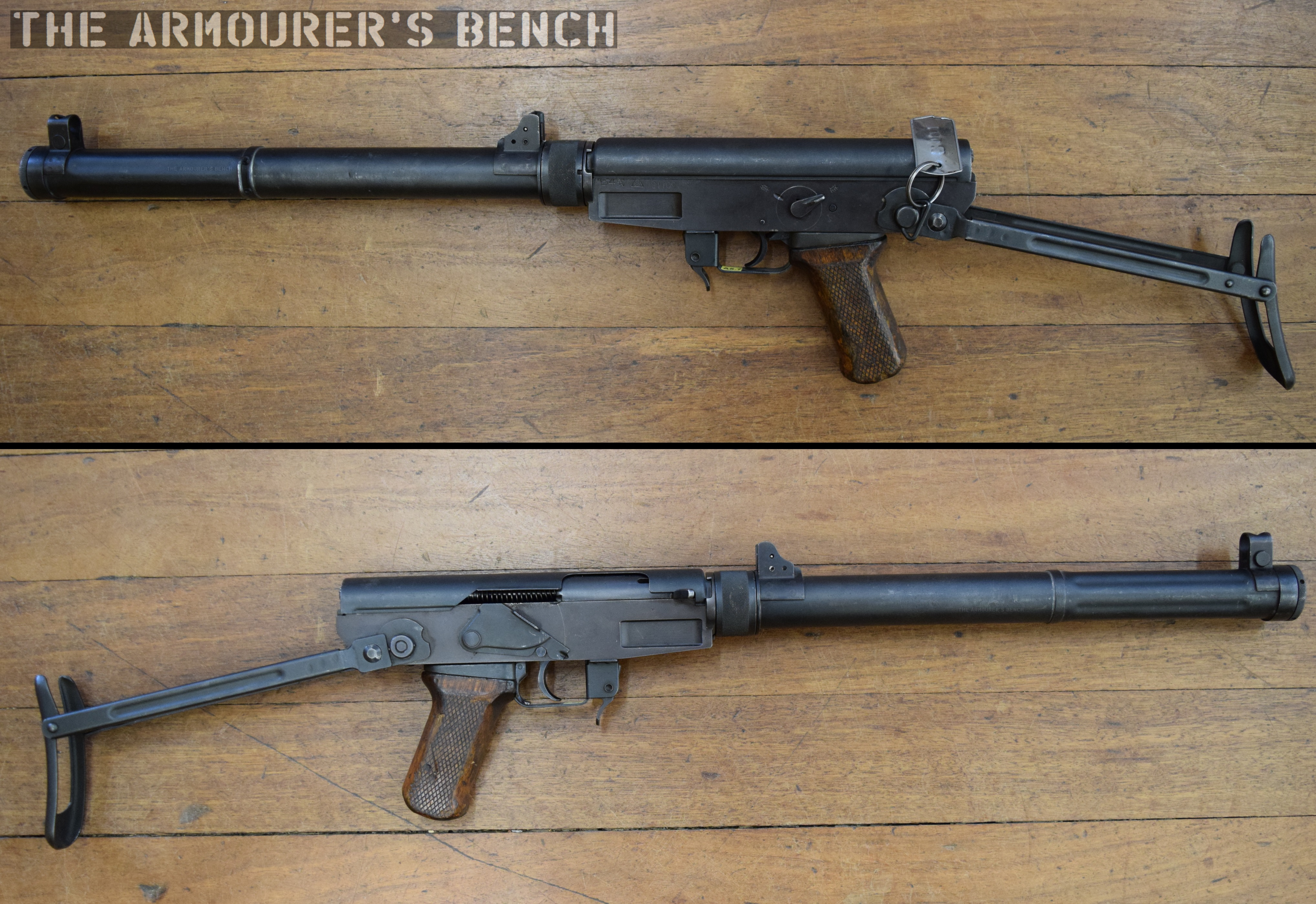
Right side of the Type 64, with stock folded (Matthew Moss)
Designed concurrently with the Type 64 suppressed pistol during the 1960s, the Type 64 SMG was developed for Communist China’s special forces for use in clandestine operations. Chambered in the standard 7.62×25 ComBloc pistol round, the Type 64 functioned best with Type 64 subsonic ammunition, a special subsonic spitzer projectile variation of the standard 7.62mm pistol round. It did not chamber the low power 7.65x17mm round used by the Type 64/67 pistols.
A close up of the weapon’s markings, including the State Factory 66 stamping (Matthew Moss)
The Type 64 fed from 20 or 30 round double stack magazines which were reportedly developed from or at least influenced by the Soviet PPS-43’s double stack, double feed magazines. The weapon used a conventional blowback action and fired from an open bolt. Its maximum effective range was approximately 200 metres with two position flip up sights ranging out at 100 and 200 metres.
The Type 64 had a milled receiver with lightening cuts and weighed in at 7.6lb or 3.5kg unloaded. It took its bolt from the Russian PPS-43 submachine gun and a trigger group inspired by the ZB vz.26 light machine gun’s, which was well liked by the Chinese military.
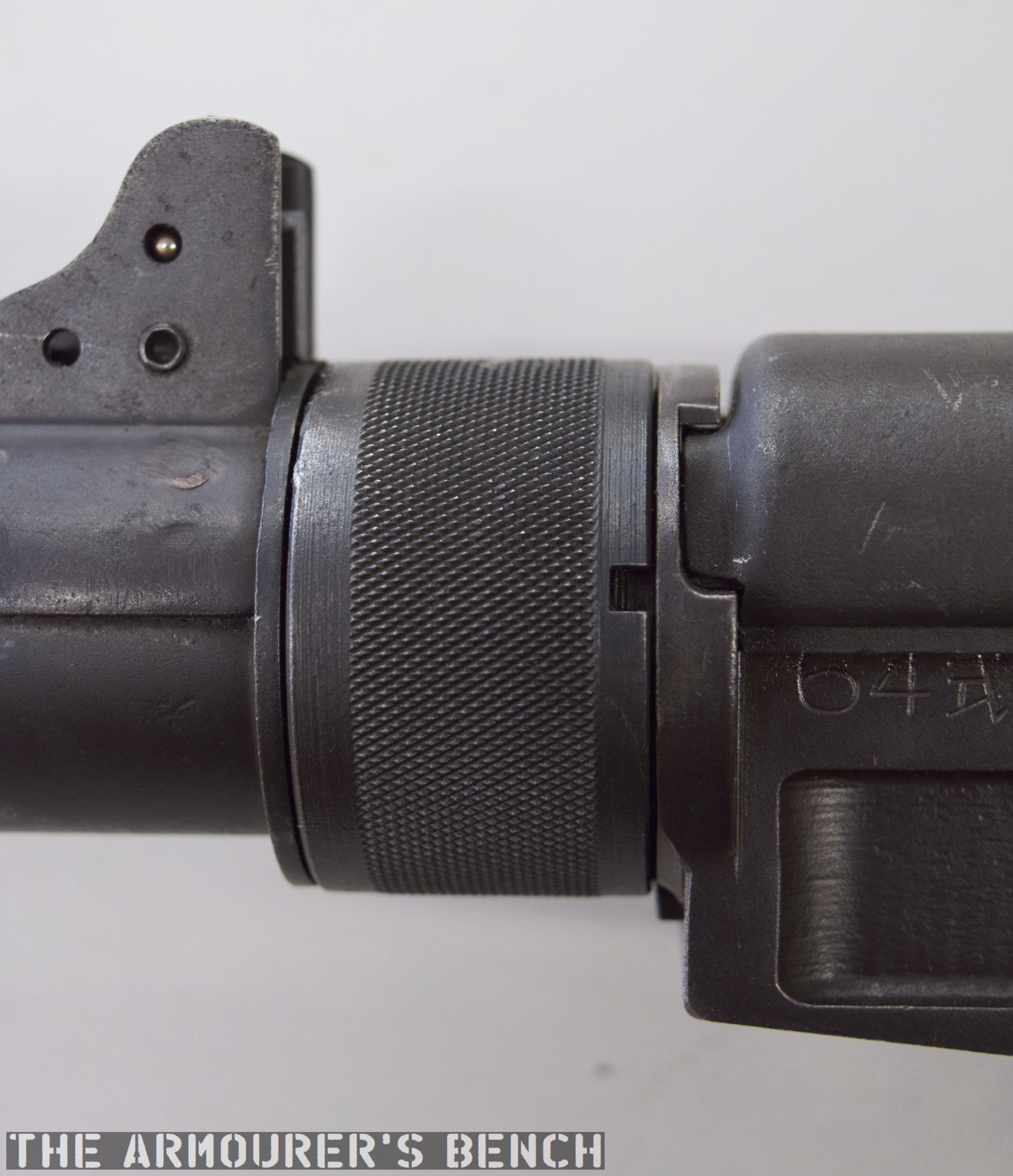
The suppressor housing is unscrewed at the trunnion with an interrupted thread (Matthew Moss)
The Type 64 shared a number of external similarities with the standard Type 56 AK-clone including its pistol grip, safety lever and under-folding stock (which is similar but slightly different to the Type 56-I’s under-folding stock).
The Type 64’s fire selector (Matthew Moss)
The weapon has a number different controls including a conventional AK-style safety-come-dust cover, on the right side of the receiver – which blocks the travel of the bolt. On the opposite side of the receiver it has a two-position fire selector for semi and full-auto – you can just about reach these when the stock is folded. The forward position is for semi and the rearward position is full-auto. Finally, the 64 also has an additional trigger block safety, taken from the SKS, which pivots forward to prevent the trigger from being pulled.
A close up of the magazine release, trigger block safety and lever safety (Matthew Moss)
According to a report written in October 1971, by the Small Arms Systems Lab of the US Army Weapons Command Research and Engineering Directorate, the weapon has an extremely high rate of fire of over 1,300 rpm.
A cyclic rate that high was the result of a combination of back pressure from the suppressor, the ammunition used and its blowback action. The Type 64’s chamber was fluted with three longitudinal cuts to aid extraction at its high rates of fire. It should be noted, however, that the 1971 US army tests were carried out with standard velocity ammunition – rather than the specialised subsonic Type 64.
The Type 64 with stock deployed, left & right profiles (Matthew Moss)
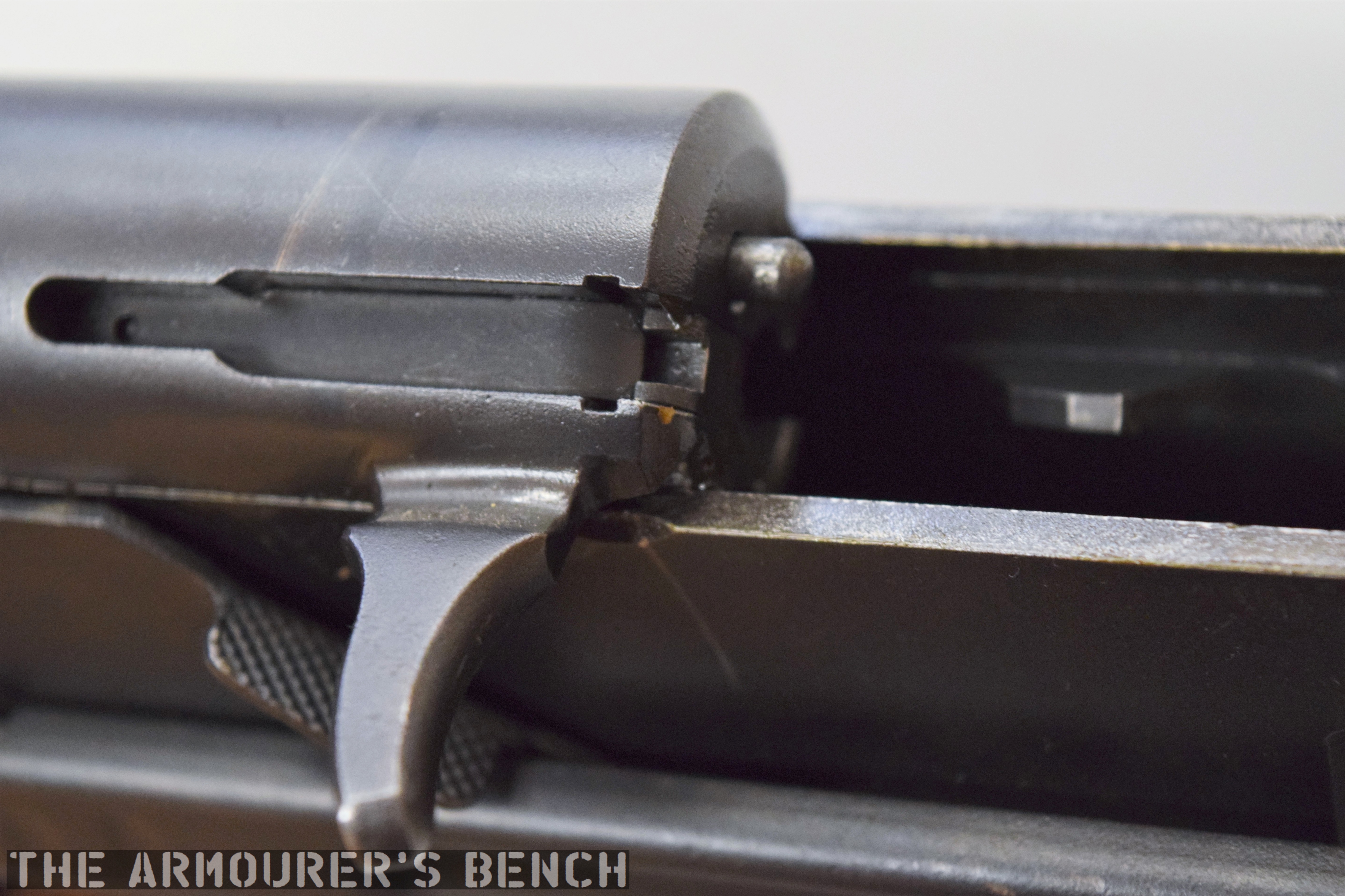
The top cover is removed by pushing in what at first appears to be a spring-loaded detent, but is actually the recoil spring guide rod. The front of the top cover is held in the receiver by a lip which fits into a slot just above the breech. The top cover itself is a thin piece of stamped sheet metal with the serial number stamped at the rear.
With the receiver cover removed and the action cocked. The Type 64 fires from an open bolt. Note the buffer at the rear of the receiver (Matthew Moss)
With the top cover removed we can see inside the action. The 64 has a single recoil spring held in place by a guide rod. At the rear of the receiver is a small plastic buffer, designed to both soak up some of the recoil energy and to help reduce action cycling noise. There is an ejector on the left side of the receiver and guide rails along which the bolt moves. To remove the bolt it is pulled fully to the rear and then tilt it upwards.
A close up of the bolt face (Matthew Moss)
The Type 64 is a pretty compact weapon despite the length of its suppressor. It has an under-folding stock, with two spring-loaded buttons at the rear of the receiver which have to be pushed in to fold and unfold the stock. When folded the weapon is 25in (or 63.5cm) long, with the stock adding 8 inches when it is deployed. The weapon can be used with the stock folded, although some of its controls are partially obscured.
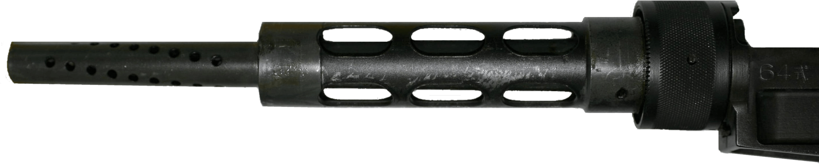
The suppressor is contained by a housing which attaches to the receiver by an interrupted thread. The Type 64’s barrel was ported with 36, 3mm vents at the muzzle-end while the suppressor has 12 metal dished baffles held captive on a pair of guide rods. The weapon’s sights are mounted on the suppressor housing which attaches to the receiver by an interrupted thread. Sadly, I didn’t have time to strip the suppressor itself but the photos below, from my friend Chuck over at Gunlab, show the Type 64’s ported barrel and baffles well.
With the suppressor housing and baffle system removed. Note the series of holes in the barrel (GunLab)
The 1971 Small Arms Systems Lab report found that the audible report of the gun, was 150db at the rear of the receiver and 157db 12 feet down range, however, this is probably not the best indication of the Type 64’s capabilities as the report states that the gun was tested with Chinese Type 51 standard velocity 7.62x25mm ammunition. Ideally, the weapon would have been used with subsonic Type 64 ammo specially developed for China’s suppressed pistol-calibre weapons. Chinese sources reportedly put the weapons noise level at 84db when using subsonic ammunition. The US report did note that while its noise suppression wasn’t outstanding, it very effectively hid its muzzle flash.
The baffle system held together a pair of guide rods (GunLab)
It appears to have been primarily used by Chinese scouts and special forces and saw action during the 1979 Sino-Vietnamese War. In the late 80s the Chinese replaced the Type 64 with the suppressed version of the Type 85 submachine gun, also chambered in 7.62x25mm, which used the same magazines, the Type 85 had a tube metal and stamped receiver which was simpler to manufacture than the 64’s machined receiver. The Type 85 has subsequently been superseded by guns like the bullpup Type 05.
Special thanks to the collection that holds this weapon for allowing me to take a look at it. As always guys thank you for watching. If you enjoyed the video please share it with friends and help us
‘Technical Notes: Chinese Communist 7.62mm Type 64, Silenced Submachine Gun’, US Army Weapons Command Research & Engineering Directorate Small Arms Systems Laboratory, J.J. Boccarossa, 27/09/1971
Secondary Sources:
Chinese Type 64 SMG, Small Arms Review, F. Iannamico (source)
Type 64 submachine gun (PR China), Modern Firearms, (source)
Chinese Type 64 suppressed SMG, ForgottenWeapons.com (source)
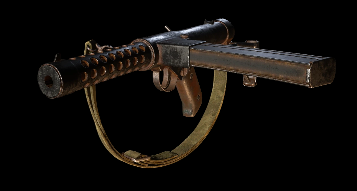
During a recent discussion over on the HF Twitter page, I was informed to my surprise that the Sterling submachine gun had been added as a DLC weapon to Call of Duty WW2. I thought it would be interesting to take a look at the model used in the game and see how historically accurate it is. I recently finished writing a book about the Sterling and have done some research into the theories of the Patchett prototypes seeing some action during the war.
The model that Sledgehammer Games, the developer, have used appears to be a mix of the early prototypes and the later production Sterlings. In terms of historical accuracy the gun should be correctly referred to as the Patchett Machine Carbine – after its designer George Patchett. It only began to be called the Sterling, after the company that manufactured it in the 1955.
Developer’s model of the COD: WW2 Sterling SMG (courtesy of Activision/Sledgehammer Games)
The model appears to share some similarities with the original Patchett prototype, including the step in the welded together receiver – the result of using left over Lanchester machine carbine receiver tubes, which was also built by Sterling. The position of the stock hinge point also appears to be in the correct place (it was later moved forward when the stock was modified). However, it appears to be feeding from a much later curved commercial pattern Sterling magazine (you can tell by the zigzag outline on the rear of the magazine and of course the curve – although seemingly not quite as curved as the real thing.) In reality the Patchett prototypes fed from Sten magazines, it wasn’t until after the war that Patchett designed his excellent 34-round magazine.
Here’s a photo of the Patchett’s original tool room prototype that I took last year while researching:
Patchett’s Original Toolroom prototype (Matthew Moss)
Note how they even replicated the slanted brazed on rear sight that was added after the first trials. The game developers, however, added a metal guard tab just in front of the ejection port – something that wasn’t added until later and they also gave the gun markings on the magazine housing that mimic the later commercial Sterling markings.
The game model also has the Sterling’s helical grooves on its breech block, something the early prototypes did not have. It seems the developers mashed together the Patchett prototype with later production Sterling L2A3/Mk4s.
Did the Patchett See Action During WWII?
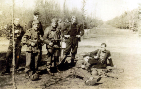
A grainy photograph, sadly lacking provenance, that appears to show members of the Free French SAS with two Patchett prototypes during Operation Amherst, April 1945 (source)
While the early Patchett prototypes may have seen action in late 1944 – 1945 with one or two prototypes possibly making it into the hands of specialist troops there is no solid evidence to support this. There is a tantalising grainy photograph of what is believed to be members of the Free French SAS on operations in the Netherlands in April 1945 (during Operation Amherst). The photo above shows what appear to be two Patchetts during a meeting with local resistance members. There is also an uncorroborated story that one prototype was carried by Lt.Col. Robert Dawson, officer commanding No.4 Commando, during Operation Infatuate but there is no documentary evidence to support this. I discuss these and several other pieces of evidence that support the idea that the Patchett/Sterling saw action in my new book on the Sterling.
I have written a book for Osprey’s Weapon series looking at the development, use and significance of the Sterling, it’s available now, you can find out more about it here.
Before its adoption by the British Army in 1954 the Patchett Machine Carbine, later better known as the Sterling submachine gun, was extensively tested all over the world. The Patchett went through nearly a decade of testing, evaluation and refinement. It was tested by British troops around the world, from West Germany to Africa, from the middle east to Malaya.
Today, we’re going to examine a unique Patchett/Sterling prototype assembled in Malaya. The gun we’re examining is officially a MkII Patchett Machine Carbine, but as the guns are better known as the Sterling we will refer to it as such from here on out. This prototype has been specially adapted with a shotgun style rib sight to help aiming in jungle conditions.
Right side profile of the jungle rib sight Patchett prototype (Matthew Moss)
It was in Malaya that the specially adapted but short-lived prototype improvement emerged. As early as December 1952, British troops were testing the gun during operations against communist insurgents in Malaya. The harsh jungle conditions were a challenge for any weapon but an early report testing a single prototype noted that the weapon performed well but one of the issues identified was that the rear aperture sight was found to be “smaller than was desirable” and the report suggested that the aperture be widened to 0.098 inches 2.5mm – the same as the Owen gun. The report also noted that the front sight “did not stand out well in relation to the front sight protectors”.
It seems that when a batch of 75 trials guns arrived in 1953, a number of them were specially adapted in theatre. It was hoped that the shotgun-style rib sight fitted along the length of the receiver would aid snap shooting in the jungle. It was intended to enable users to engage fleeting targets quicker and improve ‘first shot hit’ probability in thick jungle and heavy rainstorms.
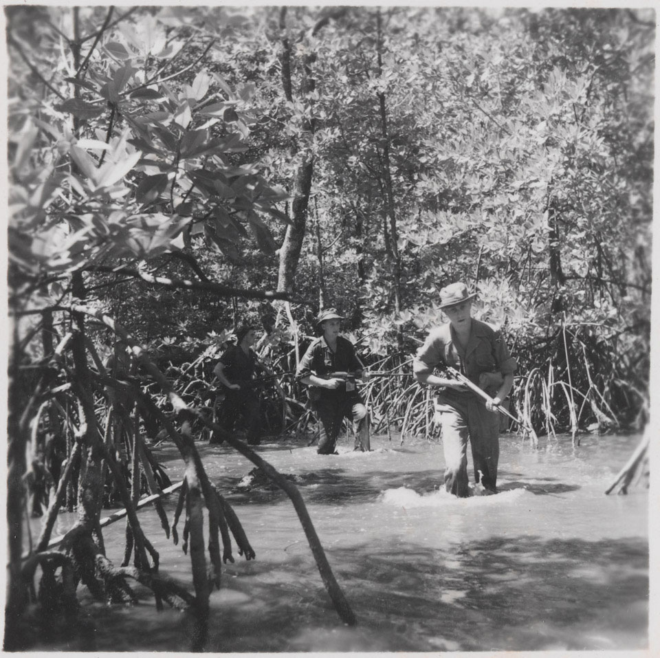
During operations in Malaya and Borneo, many scouts and point men carried shotguns such as the semi-automatic Browning Auto-5. Shotguns were favoured during jungle operations because of the ease with which they could be quickly and instinctively aimed and their exceptional close-range firepower.
The modification saw the complete removal of the standard front and rear sights and the razing on of a rib sight running along the length of the top of the gun from the muzzle to the rear sight. It appears an armourer cut down and removed the front and rear sight assemblies and used them as mounting points. The first few inches of the rib are stippled to minimise glare and a brass front sight bead has been added to help sight acquisition.
Left side profile of the jungle rib sight Patchett prototype (Matthew Moss)
The simpler sight rib also helped with another issue that was identified during early jungle testing, it removed the problem of the sights getting clogged with mud. It is unknown just how many were adapted but at least three are known to survive. The jungle-specific modifications were short-lived and not formerly adopted because the rib sight offered poor longer range accuracy.
Here are some more detail photographs of the rib sight prototype:
With the adoption of the Patchett as the L2A1, in 1954, a list of modifications based on trials recommendations was drawn up in June 1953, one of the suggestions was the enlargement of the rear sight aperture to 0.1, (2.5mm) 0.15 (3.8mm) or 0.2 inches (5mm). In August 1953, the infantry board decided that the 100 yard aperture would be 0.15 (3.8mm) in diameter while the 200 yard would be 0.1, (2.5mm). The spacing of the rear sight protectors was also subsequently widened to 0.55 inches (14mm). With these changes made the Sterling saw service in the jungles of Malaya and Borneo for over a decade during the Malayan Emergency and Indonesian Confrontation.
If you enjoyed the video and this article please consider supporting our work here.
Bibliography
Primary Sources:
‘Operational Research Section, Singapore, Technical Note No.5 – Technical Notes on Initial Trials of the Patchett Carbine in Malaya’, Maj. R.St.G. Maxwell, 1th December, 1952, Royal Armouries Library
‘Minutes of a Meeting held at the war office on Friday 7th August, 1953, to decide whether the Patchett sub-machine gun be introduced into the Service as a replacement for the Sten sub-mahcine gun’, Royal Armouries Library
I have written a book for Osprey’s Weapon series looking at the development, use and significance of the Sterling, it’s available now, you can find out more about it here.
Held in the collection of the Cody Firearms Museum (CFM), at the Buffalo Bill Centre of the West, is a most intriguing Cold War submachine gun. The weapon came from the collection of the old Winchester Firearms Museum, which the CFM inherited, it is not a test & evaluation weapon made by another company but a submachine gun designed and developed by Winchester. Those who know their Winchester history will know the company had no prior background in submachine gun design, instead being best known for their rifles and shotguns.
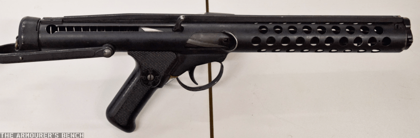
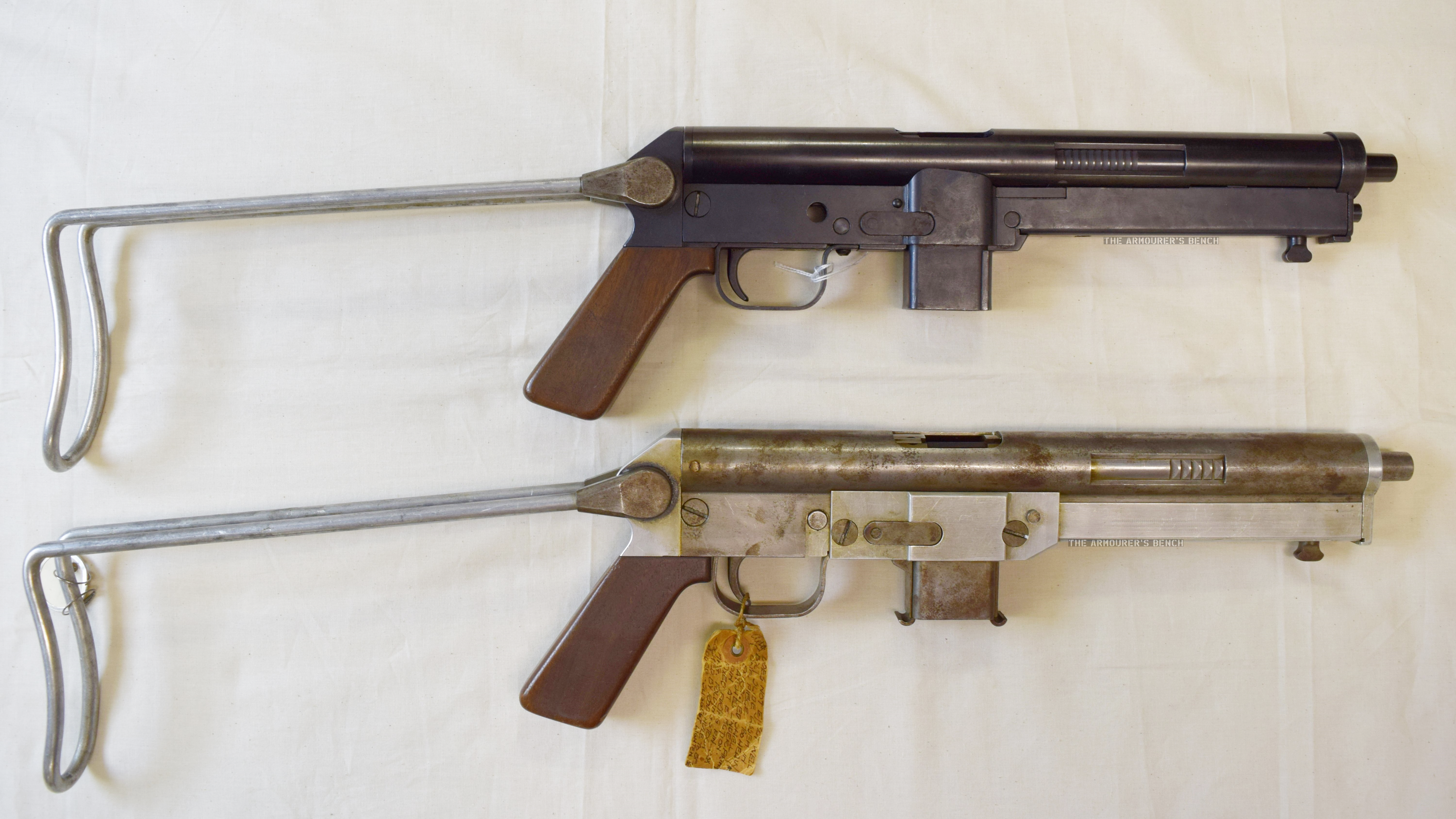
Left side profile view of the N4 and N2 Winchester submachine gun prototypes with their stocks folded (Matthew Moss)
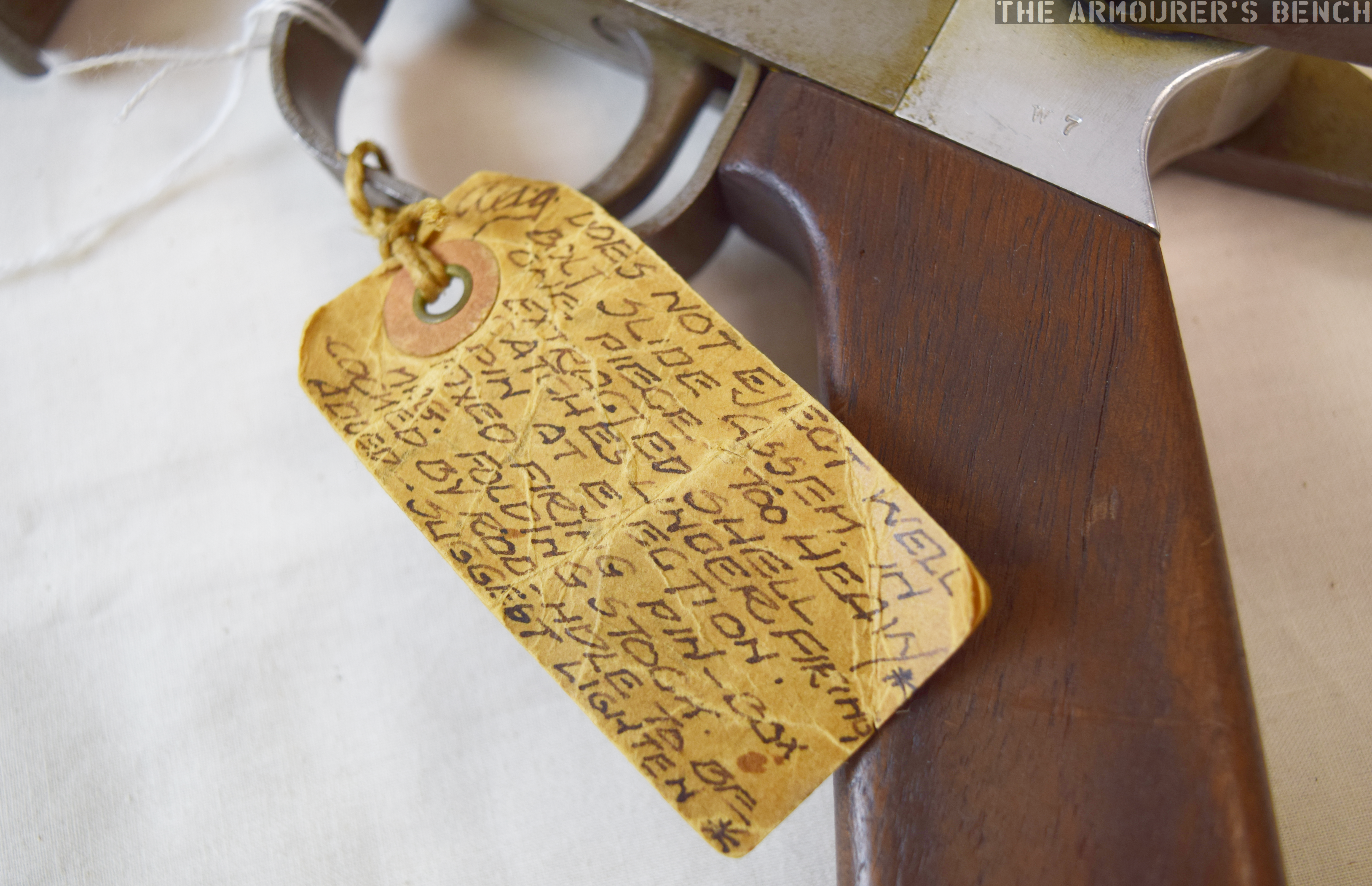
Very little is known about Winchester’s submachine gun project, but two prototype examples survive, an early ‘in the white’ model labelled ‘N2’ and another which Herbert Houze, the CFM’s former curator, designated ‘N4’ . The documentary evidence for the Winchester submachine guns is sparse, amounting to just entries in the Winchester Museum’s inventory and a faded battered item tag attached to N2. A confusing element is that the inventory simply refers to the two prototypes as N-1 and N-2, with no mention of an N4.
There is also believed to be original engineering drawings housed in the Winchester Archival collection, currently held by the McCracken Research Library, but searches by myself and library staff have been unable to locate these.
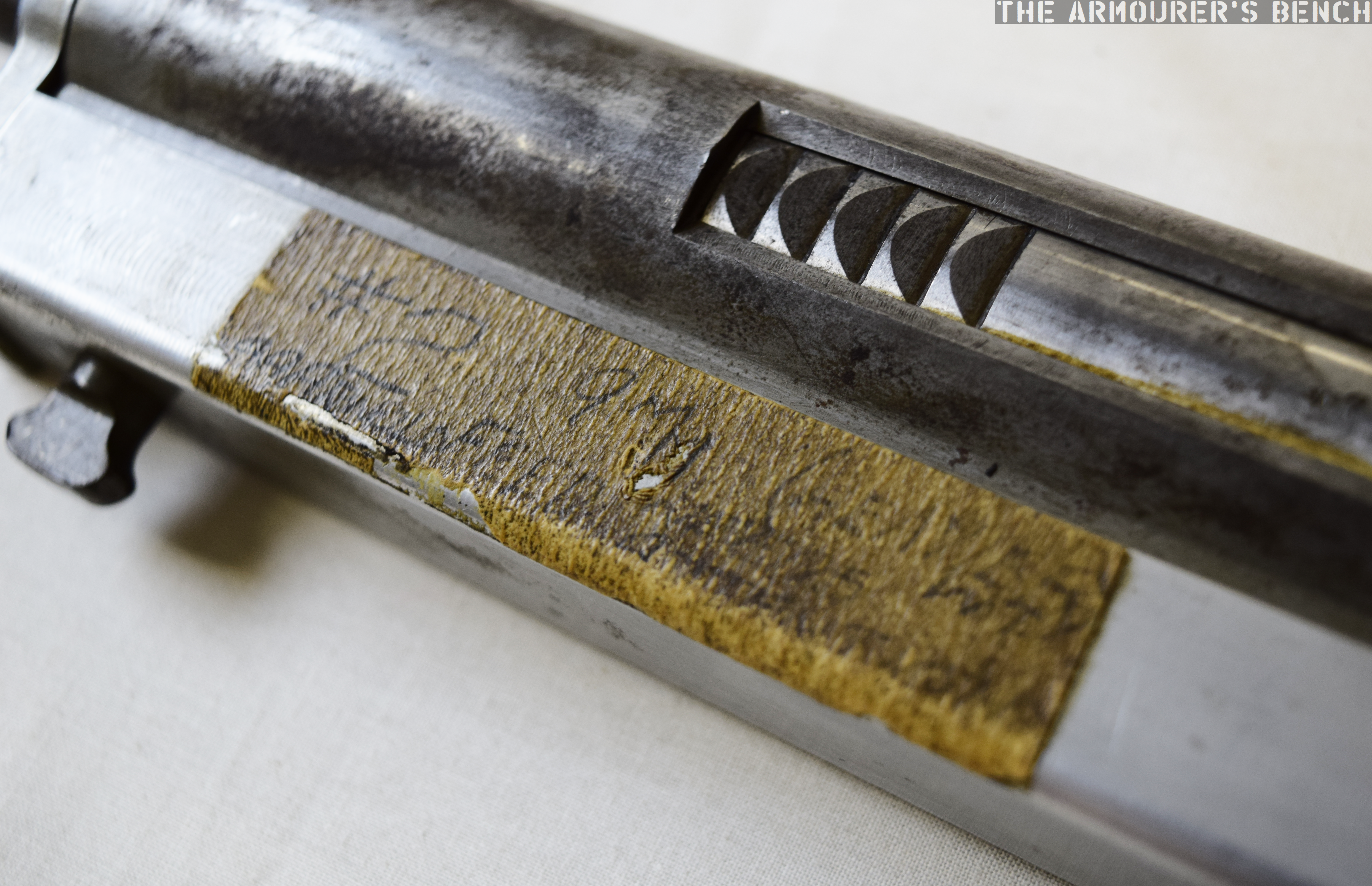
It is unclear if the tag from N2 is contemporary, perhaps added when the gun was handed over to Winchester’s museum, or if it was added later. In under 100 words it give us a short potted history of the N2 itself and the company’s programme to develop a submachine gun.
Close up of the N2’s item tag detailing the gun & program’s history (Matthew Moss)
Houze suggests the development programme began in 1955 and the tag attached the N2 suggests that development ceased in 1957, whether this is solely for that gun or the entire programme is unclear. This would make Winchester’s weapon a contemporary of the famous Israeli UZI.
The tag describes the N2 as a 9mm blowback ‘NATO Burp Gun’, followed by the name A.A. Arnold, a Winchester engineer perhaps best known for writing a series of manuals for Winchester firearms, followed by ‘dropped Dec ’57’. In his 1994 book, Winchester Repeating Arms Company: Its History & Development from 1865 to 1981, Houze suggests that the weapons were designed by A.A. Arnold and Melvin M. Johnson in 1955, for possible adoption by NATO. The association with NATO might also be the origins of the ‘N’ prefix. I have been unable to find any published patents attributed to Arnold, Johnson or the company relating to the experimental submachine gun.
I contacted NATO’s Archives who advised that they were unable to find any reference or documentation relating to a direct NATO submachine gun requirement. Another possibility is that the weapon was developed to market more broadly to NATO member nations. The submachine gun market at this time in Europe, however, was already saturated by both wartime surplus and a new generation of guns, including the Sterling, the UZI, the Madsen M50, and the Carl Gustav m/45.
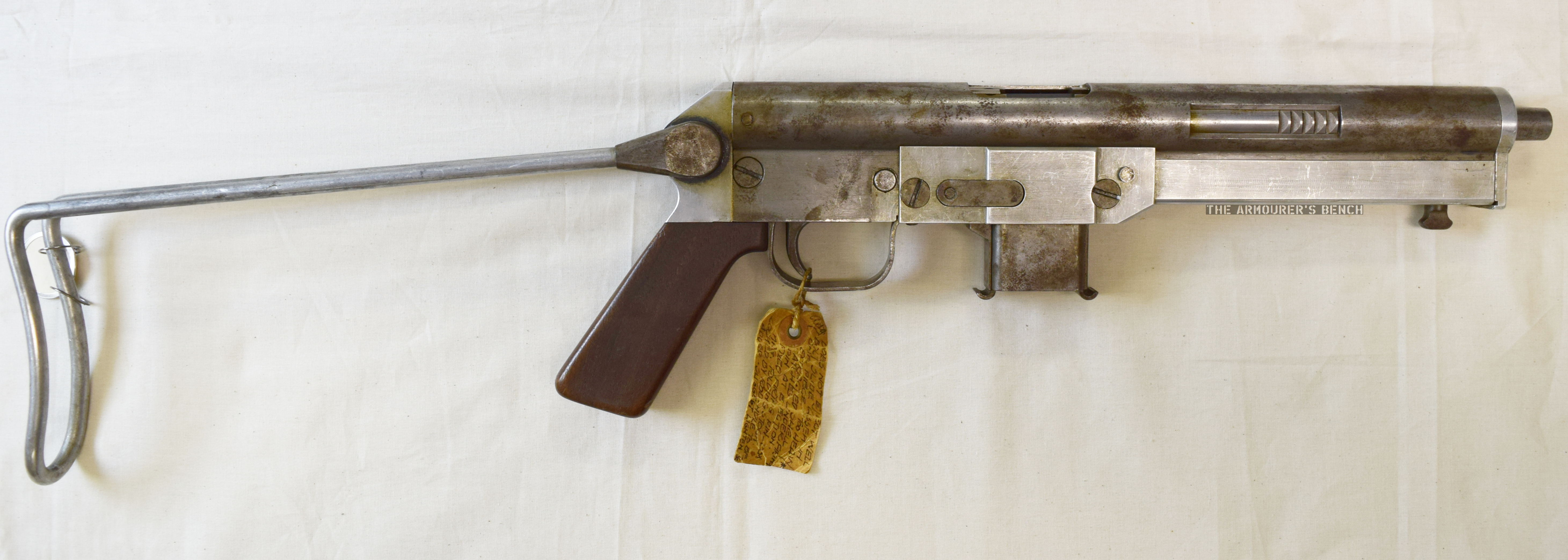
Right side profile view of the N2 ‘in-the-white’ prototype with its stock deployed (Matthew Moss)
The reverse of the N2’s label documents the prototype weapon’s reliability and feeding problems. The tag states that the N2 did “not eject well” and that the bolt slide assembly was too heavy. It also highlights failures to cycle properly with extracted cartridge cases catching under the firing pin. The label then gives a brief description of some of the N2’s features: “fixed firing pin, 33x Mag. Folding stock.” Interestingly, it also notes that the weapon would be cocked by a rod – the hole for which had not yet been added. The tag ends with a suggestion that the heavy one piece bolt assembly should be lightened.
Close up of the N2’s difficult to decipher tape note (Matthew Moss)
N2 itself also has a piece of masking tape, on the recoil spring assembly cover, with its serial number and calibre written on it, along with A.A. Arnold’s name and some words that are too difficult to make out, but include ‘feed’.
Houze has also suggested that Melvin Johnson, designer of the Johnson rifle and light machine gun who joined Winchester as a designer and adviser in the early 1950s for a short time, and Stefan Janson, designer of the Brtish E.M.2 bullpup and subsequent Winchester engineer, both worked on the project. However, I have been unable to find any documentary evidence of their involvement.
Examining the N2:
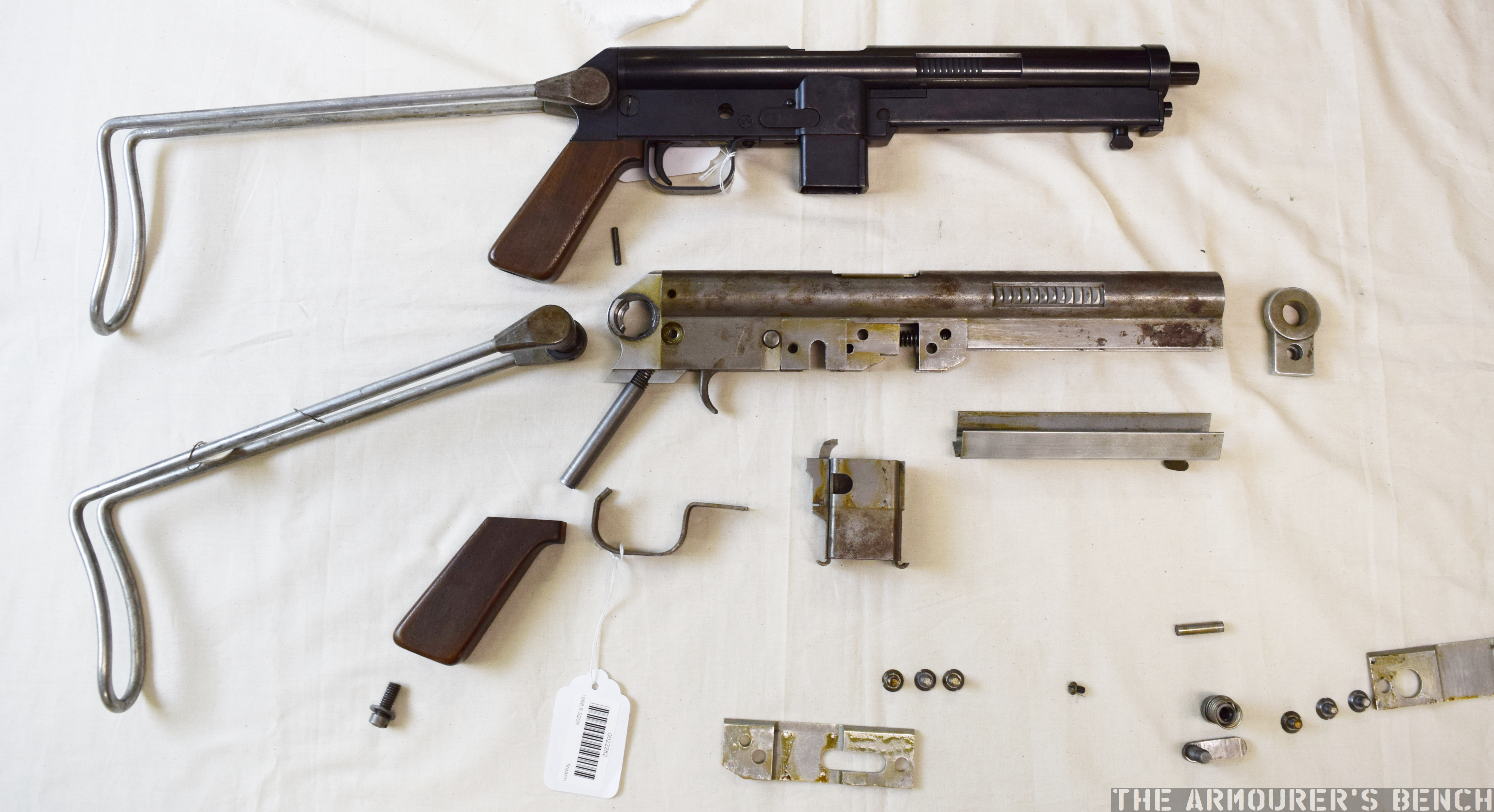
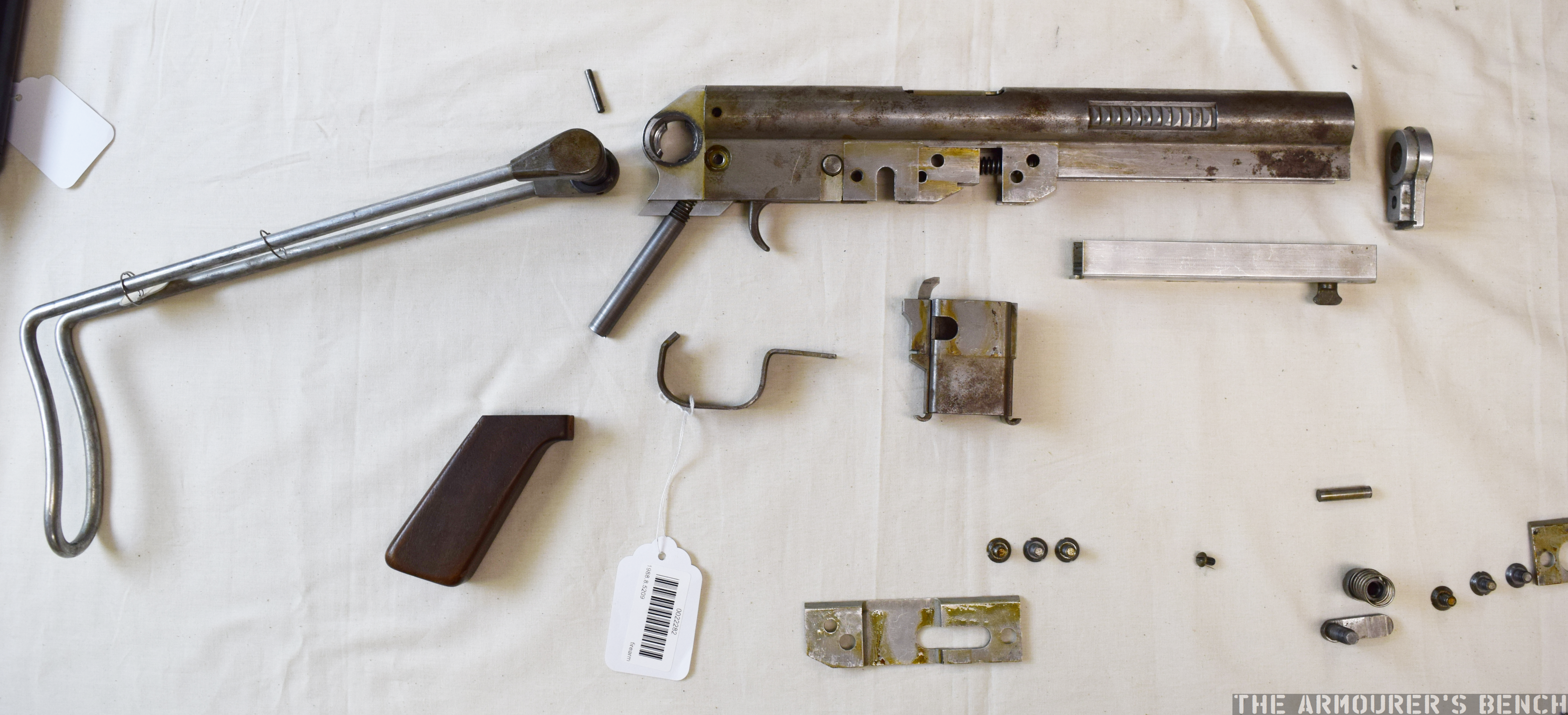
Winchester N4 and disassembled N2 prototype (Matthew Moss)
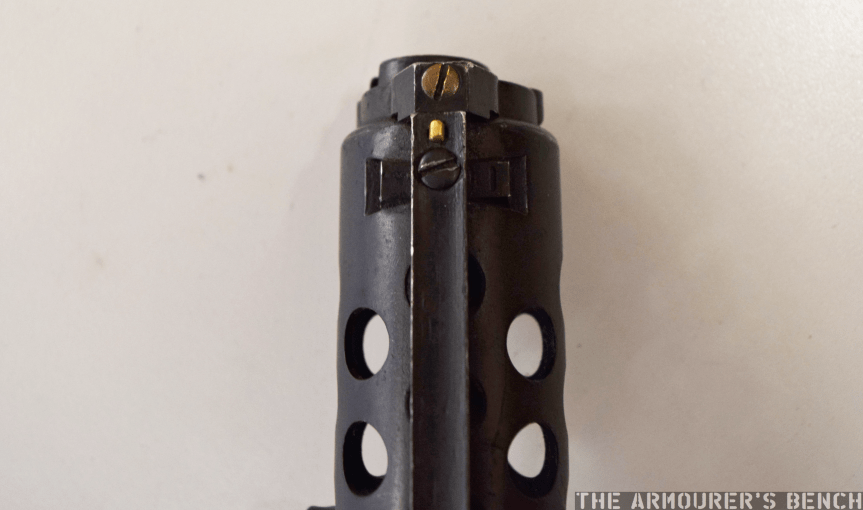
We can learn a lot from hands on examination of the two Winchester ‘N’ prototypes. Examining N2 we find that the receiver is made up of a piece of shaped sheet metal with a rounded upper half containing the barrel, bolt and cutouts for the grip points on the bolt assembly that allow charging. The bolt assembly rides over the rear portion of the barrel and projects back into the receiver. The lower section of the stamped receiver is rectangular and has a cut out for a separate magazine housing and fire control mechanism consisting of a trigger and push through safety – which we did not remove during disassembly. The N4 is missing its safety.
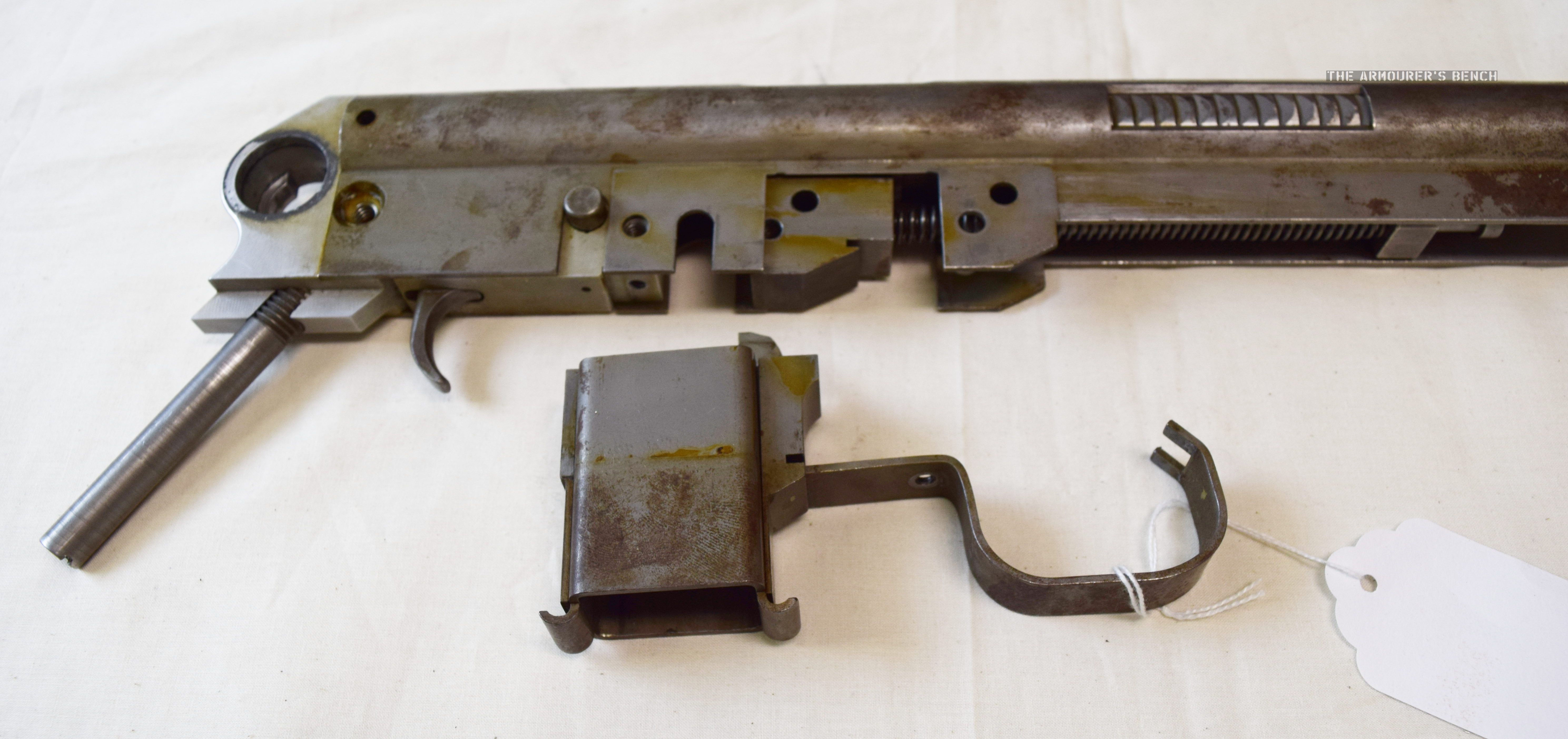
Close up of the N2’s magazine housing and trigger guard, note also the trunion freed from the receiver (Matthew Moss)
In the N2, the magazine housing is held in place by the stamped metal trigger guard which rocks into a notch behind the trigger and at the front interfaces with a notch in the magazine housing which has to be placed in the receiver at the same time, both are then held in place by a screw. This was changed in the later ‘N4’ with the trigger guard as a separate independent piece.
Winchester N2 Prototype Reassembly:
The side plates, muzzle end cap and recoil spring assembly cover all made from Aluminium – ostensibly to reduce weight. The submachine gun prototypes both use a pinch cocking method similar to that seen in the earlier British BSA WELGUN developed during WWII. The recoil spring proved to be too strong to cock easily, the addition of ‘rod’ cocking handle is suggested on the N2’s tag. The blued, later N4 prototype, however, is still lacking a conventional cocking handle. The pinch cocking method is not ergonomic, the user’s fingers could easily be caught by reciprocating bolt in charging cut outs in the receiver.
The N2 prototype disassembled, sadly we were unable to free the bolt from the receiver (Matthew Moss)
Another ergonomic consideration is the Winchester’s submachine gun’s unusually swept back pistol grip angle, the angle of the forward grip made by stock when folded is also similarly angled. Both the weapons have a push though safety selector just above the trigger (likely safe & fully automatic, but could not check as gun unable/difficult to cycle the prototypes easily). The weapon likely fed from a double stack, single feed magazine – either of an similar pattern to the MP40 or proprietary. The N4 seen in Houze’s 1994 book is shown with an MP40 magazine. UZI magazines fit the weapon but don’t lock into place.
The basic design does not change substantially between the prototypes with the control configuration, folding wire stock, pistol grip angle and magazine housing dimensions remaining the same. The N4, however, differs from the earlier prototype in a number of respects. The N4’s nose cap now fits over the rounded half of the receiver, rather than sitting flush and the cut outs in the upper receiver to access the bolt assembly for charging have been moved back slightly.
Right side view of the N4 blued prototype, note the half cocked bolt and the narrower grip serrations on the bolt assembly. Note also the intersection points of the recoil spring assembly cover and the upper receiver (Matthew Moss)
The later N4 model has pins in place of some of the screws used on the N2. The side plates have been replaced by a one-piece recoil spring assembly cover which projects back further over the magazine housing to the rear of the receiver. The most fundamental difference between the two is that it appears that the front part of the N4’s receiver has been significantly altered with the lower receiver at the front of the gun removed. It appears to have been replaced by the recoil spring assembly cover which appears to slot into the receiver. Sadly, we didn’t have time to disassemble the N4 to examine this.
The N4’s bolt assembly also has more serrations, in a slightly different orientation, on its bolt assembly gripping area, but still no charging handle as recommended on the N2’s tag. The ejection port on the blued prototype is also at a position closer to 12 o’clock when compared to the N2s.
Right side profile view of the two prototypes with their stocks deployed (Matthew Moss)
The N2 has a metal trunnion block, that the recoil spring guide rod screws into, this is held in place within the receiver by a cross pin. The bolt appears to be removed through the rear of the receiver once the stock assmbly/end cap is removed and the bolt assembly freed.
The folding stock was retained by spring tension of the wire metal stock against a wingnut-shaped catch that is riveted onto the recoil spring assembly cover. The stock is locked by a spring loaded push button system similar to the MP40s, this is not particularly sturdy. The shape of the wire stock itself is reminiscent of the US M3. When folded the butt of the wire stock acts as a front grip, the retention of the stock is surprisingly strong and stable.
Intriguingly, the Winchester Museum inventory notes that the guns are designated the N-1 and N-2, with an additional wooden model of the ‘Nato Burp Gun’ being transferred along with a box of duplicate parts in steel for the N2’s aluminium parts.
If you enjoyed the videos and this article please consider supporting our work here.
Winchester Repeating Arms Company: Its History & Development from 1865 to 1981, H. Houze (1994)
My thanks to the Cody Firearms Museum at the Buffalo Bill Center of the West for allowing me to examine and film the Winchester submachine gun prototypes. Special thanks to the CFM’s assistant curator Danny Michael for helping disassemble the N2.
All photographs taken by Matthew Moss, courtesy of the CFM & the Buffalo Bill Center of the West. Please do not reproduce photographs without permission or credit.