The interwar period saw many countries under invest in their militaries, Britain was no exception. One area of equipment that went lacking for many years was adequate anti-tank weaponry. This was finally addressed in the mid-1930s with the Superintendent of Design at Woolwich arsenal developing the 2pdr anti-tank gun, which adopted in 1936.

Prime Minister Winston Churchill watches a demonstration of a 2pdr AT gun (Imperial War Museum)
Officially designated the ‘Ordnance QF 2-pounder Mark IX’, the 2pdr was an attempt to provide a light and mobile high velocity anti-tank gun which was relatively cheap to produce and effective against contemporary tank armour. It was also intended that the gun would itself be mounted in armoured vehicles and tanks.
In 1934 development contracts were awarded to Woolwich and the Vickers-Armstrong company for the design of carriages for the new gun, the Vickers Mark I and the Mark II from Woolwich. The Mark I had a slightly different armour shield and leg design.
These two carriages were tested against one another with trials taking place from November 1935 through to the summer of 1936. The Vickers design initially won out and the first order for 44 guns was placed in 1936. A subsequent re-evaluation of an improved version of the Woolwich carriage found it superior and the Mark II carriage was adopted.
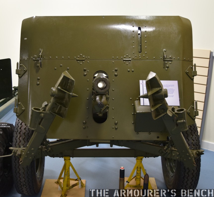
The business end, note the 2pdr’s tall armour shield to protect the crew (Matthew Moss)
The 2pdr fired a 40×304mmR armour piercing round which weighed 2lbs 6oz or 900g and was effective out to 1,000 yards against up to 1.5 inches of armour. It had a four man crew and was capable of firing up to 20 rounds per minute. It had an all steel barrel with a removeable breech ring and a vertically sliding breech block. The gun had an innovative and very stable three-legged collapsible platform, rather than a split-trail carriage, that also allowed the gun to be rotate through 360 degrees when its road wheels were removed. The 2pdr had a semi-automatic action with a hydraulic/hydrospring recoil system which used hydraulic fluid to absorb the gun’s recoil. This allowed the gun to be rapidly aimed and fired despite recoiling approximately 20 inches (or ~50cm).
A number of variants of the gun were developed during the war, with the original Mark IX, a simplified production model the Mark IXA, the Mark X which had a barrel made of higher-yield steel which was not autofrettaged – making it easier to manufacture and the Mark XA which was produced to lower tolerances and able to use the Littlejohn adapter.
Here’s a Royal Army Ordnance Corps training film on the 2pdr (courtesy of the AWM) in full:
Weighing around 1,800lbs or 816kg (or 4/5 of an Imperial Ton) the 2pdr was deemed to be too heavy for the infantry it had been designed for and in 1938 it was transferred to the Royal Artillery. Typically the guns were grouped together in anti-tank battalions each with three batteries made up of four troops which operated four guns each. That’s 16 guns per battery and 48 guns per battalion. Typically a battalion would be assigned to support a division. They were designed to be towed by a variety of vehicles with trucks, jeeps and Universal Carriers often being used.
The 2pdr was typically equipped with a No.24B 2x sighting telescope, located on the left side of the gun. It also had an iron sight but the armoured shield had to be lowered to use it. On the right side of the breech an ammunition box, holding 16 rounds was be stored for easy access, another two boxes holding 8 rounds each could be strapped to the carriage behind the ammunition box (described as the emergency ammunition box). The rest of the ammunition in twelve more 8-round containers, giving a total of 96 rounds assigned to each gun, was carried on the truck which towed the gun.
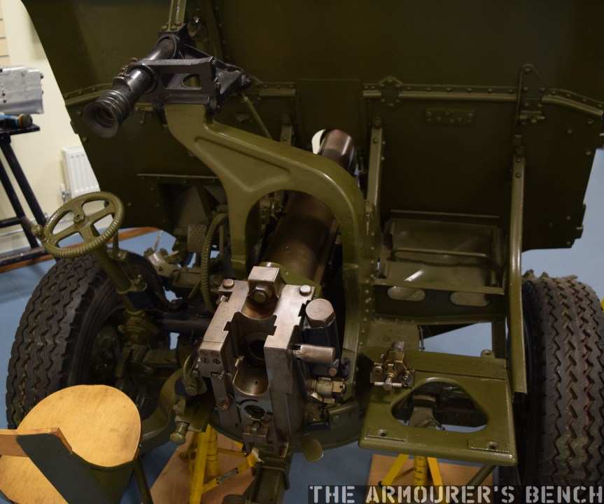
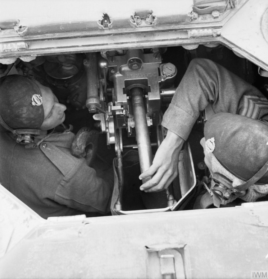
A view of the gun from behind its shield, on the left the gunners sear, the aiming scope, traverse and elevation controls and on the right the space for the ammunition boxes (Matthew Moss)
The gunlayer sat in a small seat mounted to the carriage and the loader knelt to the right of the breech. The gun was turned by a small traversing wheel operated by the gunlayer. In low gear one rotation of the wheel would turn the gun 3 degrees, in the higher gear (activated by the right foot pedal) one rotation traversed the gun 20 degrees. This meant the gun could be traversed the full 360 degrees with 18 rotations of the wheel. The right hand wheel controlled elevation of the barrel. The gun was fired by the gunlayer using the left foot pedal or two emergency firing levers if the pedal became inoperable. While the breech would typically open automatically ejecting the spent shell casing after firing a breech handle was also located on the right side of the breech.
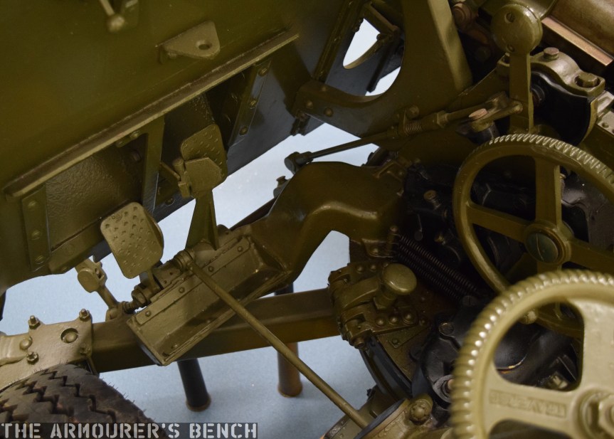
The 2pdr’s foot pedals: traverse gear on the right, fire pedal on the left (Matthew Moss)
The gun could be brought in and out of action in under a minute, including removing or replacing the road wheels. The 2pdr could, however, be fired from its road wheels, this was described as ‘emergency action’. The wheels limited the traversing arc of the gun and turns greater than 14 degrees right or 10 degrees left had to be done by lifting the gun’s trail and turning it manually. While less stable and accurate the gun could be brought into action from being towed in less than 20 seconds.
In 1939, the British Expeditionary Force to France embarked with 509 2pdrs. During the 1940 Battle for France the 2pdr was found to be an adequate anti-tank gun. One problem identified with the 2pdr was that its armour shield, designed to protect the crew, gave it a quite high profile making it easier to spot and more difficult to conceal.

A view of the breech and down the barrel of a 2pdr (Matthew Moss)
During the retreat to Dunkirk and subsequent evacuation all of the guns brought to France were lost. 60% of Britain’s 2pdr Anti-Tank guns were left behind in France, just 333 guns which hadn’t accompanied the BEF remained. Many of the guns captured after the Dunkirk evacuations entered German service under the designation 4.0cm Pak 192(e).
As the thickness of enemy armour increased the 2pdr began to struggle. The German Panzer II had 1.2 inch thick frontal armour while the Panzer III more than doubled this to 2.8 inches. On paper at least the 2pdr, firing a APHV round, could penetrate up to 2.2 inches of armour at 500 yards (460m). But in reality the Panzer III was the last German tank the 2pdr could expect to engage with a decent chance of success. With the emergence of the later mark Panzer IV, with their 50mm or 2 inch thick frontal armour, they became much less effective. If not adequately concealed gun crews could expect to be engaged by AP and high explosive rounds from the Panzers at ranges outside their effective engagement range.
Despite this, however, the 2pdr proved to be a more than a match for Japanese tanks such as the Type 95 Ha-Go light tanks, which had armour less than an inch thick. At the Battle of Muar in Malaya, in January 1942, Australian 2pdrs, of the 13th Battery, 4th Anti-Tank Regiment, knocked out six, of possibly eight or nine, Japanese tanks as they attacked up a road near Bakri. Sgt. Charles Parsons, commander of one of the guns was awarded the Distinguished Conduct Medal (DCM). Interestingly. the Australians referred to the QF 2pdr AT Gun as the “Tank Attack 2pdr” apparently a designation common to Australian anti-tank weapons as they also called the PIAT the Projector, Infantry, Tank Attack.
The 2pdr remained capable of destroying heavier Japanese tanks too, the Type 97 Chi-Ha medium tank had at 1 inch thick front armour which the 2pdr could easily penetrate at ranges of over 1,500 yards.
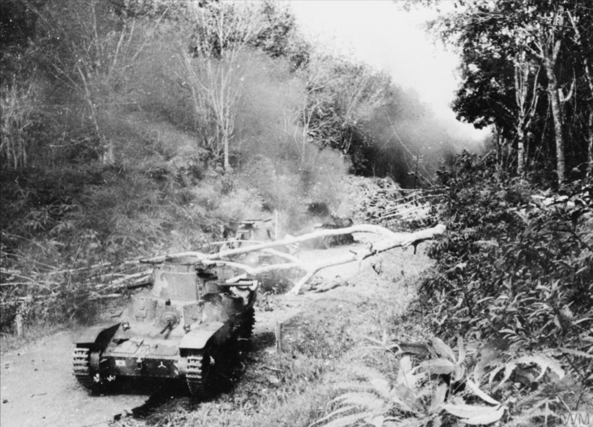
Photograph of knocked out Japanese Type 95 tanks during the Battle of Muar (Imperial War Museum)
Lieutenant Ben Hackney of the Australian 2/29th Battalion described the engagement during the Battle of Muar:
“A couple [of tanks] attempted to turn and make a get-away but still those boys with the anti-tank guns were sending a stream of shells into them. At last they could not move forward any further and became as pill-boxes surrounded, sending fire in all directions; until one by one they were smashed, set on fire, and rendered useless and uninhabitable. There came then from the tanks sounds which resembled an Empire Day celebration as the ammunition within them burnt, and cracked with sharp bursts, and hissed, with every now and again a louder explosion as larger ammunition ignited.”
In addition to being used as a towed anti-tank gun the QF 2pdr was used in a wide range of light and cruiser tanks, it provided the main armament for the Matilda II, the MKVII Tetrach light tank, the first six Marks of the Valentine infantry tank, the MKI & MKII Crusaders, the Cruiser Marks I to IV, the Covenanter tanks and it was also used in the Australian cruiser tank, the AC1 Sentinel.
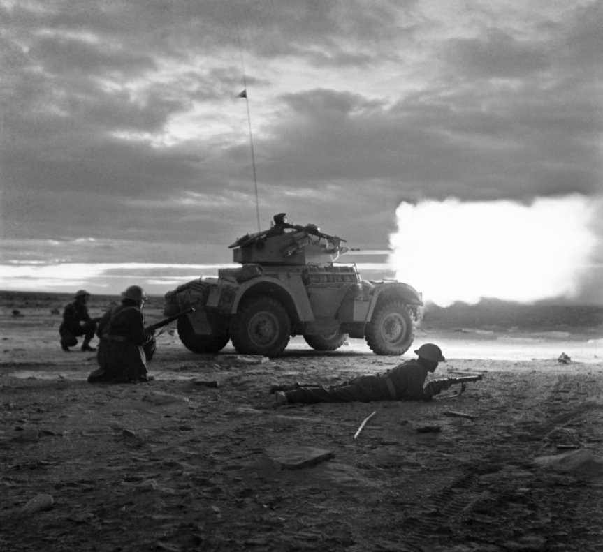
It was also widely used to arm armoured cars including the Daimler, the MKI AEC, the MKI Coventry and the Marmon-Herrington Armoured Car. In the desert it was also mounted and operated simply on the back of adapted trucks – known as Portees. Trucks built by Chevrolet, Ford or Morris were all pressed into service to create Portees. The 2pdr was deployed on its tripod on the truck bed with its wheels removed. In this setup the guns became highly mobile with the crew able to operate the gun from the truck moving in and out of action rapidly. They were widely used in North Africa with a number of medals including a Victoria Cross being awarded to men who manned them.
Second Lieutenant George Ward Gunn, J Battery, Royal Horse Artillery, was awarded a posthumous Victoria Cross for his actions in November 1941 during Operation Crusader. Gunn commanded a troop of four Portee 2pdrs which engaged a German counter attach, with all but one of his guns knocked out and the remaining gun’s crew killed and the truck on fire, Lieutenant Gunn manned the gun himself, engaging the enemy at 800 yards, he managed to destroy two Panzers before he was killed.
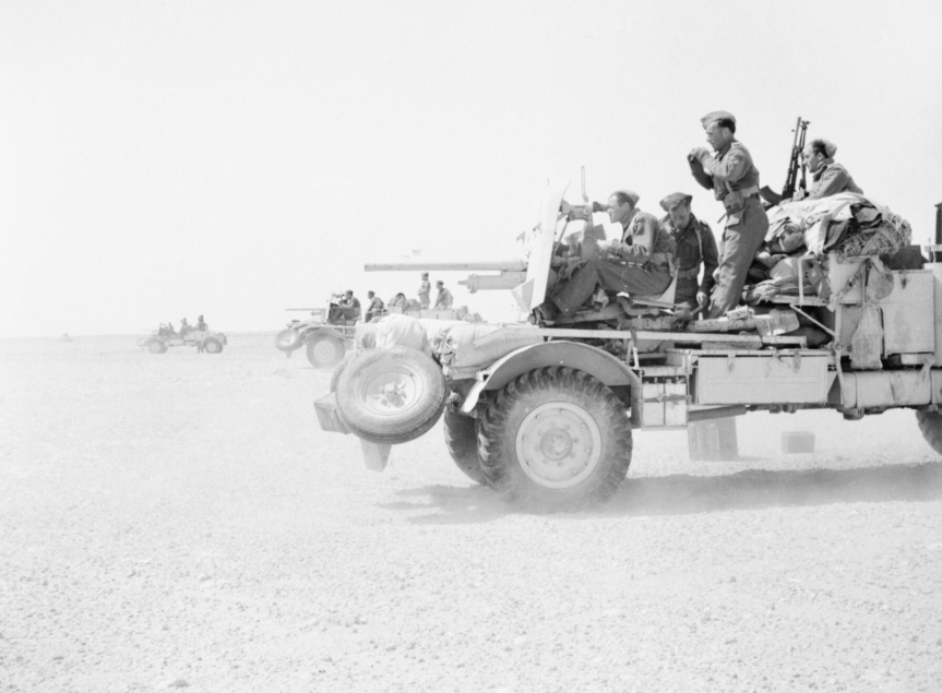
Battery of 2pdr Portees training in North Africa (Imperial War Museum)
The example we are examining began its life as a Mark IX but was subsequently upgraded into a Mk XA, capable of using a Littlejohn adaptor. The Littlejohn adapter used the squeezebore principle, the device was about a footlong with a smooth tapered bore. With the adaptor fitted to the muzzle of the 2pdr the round would be compressed by the taper going from 40mm to 30mm in diameter. This had the effect of increasing muzzle velocity giving the round a flatter trajectory and more energy. An armour-piercing, composite non-rigid round with a tungsten core was used, designated the APSV (from ‘armour-piercing super velocity’). It had the effect of almost doubling the muzzle velocity of the APSV round when compared to the original 2pdr AP shell. The adaptor was invented by Czech designer, František Janeček, the founder of the JAWA motorcycle company. The Mk I Littlejohn device entered production in January 1943 and the Mk II was approved in May 1944.
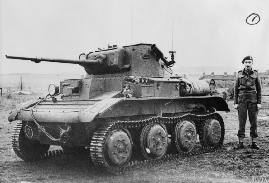
Tetrarch Mk I light tank with Littlejohn adaptor (Imperial War Museum)
While design of the 6pdr anti-tank gun, the 2pdr’s replacement, had been completed by 1938, production of the gun did not begin until 1942. Following the huge losses at Dunkirk and with invasion believed to be imminent the decision was taken to focus on the 2pdr gun as its production line was already established. They remained in service throughout the war equipping anti-tank batteries and armoured vehicles. Over 34,000 2pdr anti-tank guns were produced between 1936 and 1944, over 11,000 of these were deployed as anti-tank guns on carriages while the rest were used in various vehicles.
If you enjoyed the video and this article please consider supporting our work here.
Specifications:
Overall Length: 135.5in or 343cm
Weight: 1,800lbs or 816kg
Action: Semi-automatic, hydrospring recoil buffer
Calibre: 2pdr or 40×304mmR
Elevation: -13 / +15 degrees
Traverse: 360 degrees
Rate of fire: 20 rounds per minute
Bibliography:
Anti-Tank Weapons, T. Gander, (2000)
British Anti-Tank Artillery 1939-45, C. Henry (2004)
‘British equipment Losses at Dunkirk and the Post-Dunkirk Situation’, WWII Equipment.com, D. Boyd, (source)
2 Pounder Anti-Tank, Royal Army Ordnance Corps (RAOC) training film, via AWM, (source)
‘Singapore and Burning Tanks’, via AWM, (source)
Australian Army Second World War Official Histories, via AWM, (source)
Victoria Cross Citation 2nd Lt. G.W. Gunn, The London Gazette, Sup. 354530, 17/04/1942, (source)
Our thanks to the collection at which this video was filmed, we thank them for access to the collection.


