By 1895 Winchester had been considering a slide-action rifle for some time, in 1882 William Mason had begun work on one (US Patent #278987) to counter Colt’s slide-action Lightning only to drop it. Finally in 1890, Winchester introduced a slide-action .22 calibre rifle developed by John Browning. The Model 1890 became extremely popular.
Between 1887 and 1895 Browning patented four slide-action rifle designs. The first of these, US patent #367336, was granted in July 1887, this was followed in 1888 by US patent #385238. In September 1890, the Browning brothers were granted US patent #436965, which along with the previous 1888 patent protected what became the Model 1890. Three years later Winchester introduced the Model 1893 pump action shotgun, that would eventually evolve into the famous Winchester Model 1897.
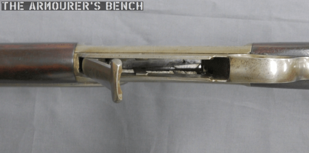
Right-side close up of the rifle with its action open (Matthew Moss)
Finally, April 1895, Browning filed a patent for a design for a .30 calibre rifle which was granted in September 1895 (US patent #545672) This patent covers the rifle we’re examining here. The rifle itself is a slide or pump action in long barrelled configuration which Winchester described as a ‘Musket’.
The September 1895 slide-action design was purchased by Winchester but like so many other Browning designs, it never entered production and Winchester purchased the design purely to secure it and prevent other rival manufacturers picking it up. Winchester instead went with a lever-action design, patented in November 1895 (US #549345), which became the famous Winchester Model 1895.
A left-side view of the rifle’s receiver with Browning’s patent overlaid (Matthew Moss)
The September 1895 slide or pump-action rifle design had a laterally camming locking breechblock. As we can see, externally Browning’s toolroom prototype looks somewhat similar to the contemporary Winchester Model 1895, with a single-stack integrated box magazine but with a pump sleeve rather than a lever.
An action-bar connects the slide/pump to the front of the breechblock/bolt carrieron the right-hand side of the rifle. The slide handle itself is made of a U-shaped piece of metal which wraps around the rifle’s forend. The slide has been roughly cross hatched to improve grip. There is a channel cut into the furniture for the action arm’s attachment point to travel. The slide is attached to the arm by a pair of screws.
A close up of the rifle’s slide/pump handle (Matthew Moss)
However, Browning developed this prototype to allow loading of the magazine from below rather than through the top of the receiver. He added a hinged floor plate, with a spring loaded follower, that allowed loose rounds to be dropped into the magazine and then closed.
As we open the magazine, hinging the cover plate down, we see the carrier flip down against the plate to allow loading. The rifle was designed to be loaded from below with the bolt forward.
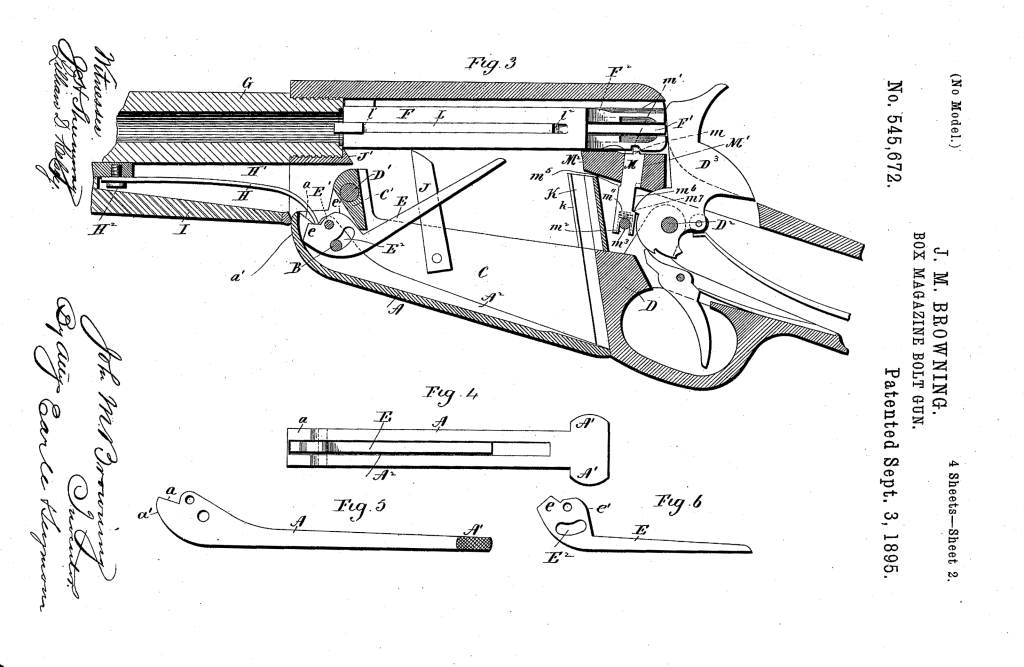
Browning’s September 1895 patent (US Patent Office)
In the patent description Browning explained that his aim was to improve breech-loading box-magazine firearms by designing:
“…a simple, compact, strong, highly effective, and safe gun, containing comparatively few parts and constructed with particular reference to provision for charging the box-magazine with cartridges from the bottom of the frame of the arm while the breech-bolt is in its closed position, so that the arm may be charged without operating its action mechanism or disturbing the cartridge in the gun-barrel, if one is there.”
Browning’s September 1895 patent (US Patent Office)
From the original patent drawings we can see the flat spring which acted on the carrier running below the barrel, ahead of the magazine. Inside the magazine are a pair of what Browning refers to as ‘spring fingers’ these act on the cartridges inside the magazine and keep them properly aligned, seen here in Fig.7 of the patent. In Fig.8 we can see what Browning calls a ‘box-like guideway’ which guide the rims of the cartridges, “preventing the cartridges from being displaced while being fed upwards.”
The rifle’s breechblock locked into a recess in the left side of the receiver, tilting at an angle with the rear of the breechblock canting to the left. When the pump handle was pulled rearwards the breechblock cammed laterally to unlock the action, extracted and ejected any spent casing and when the slide/pump was returned forward a new cartridge was picked up from the magazine, chambered the breechblock locked again ready to fire. The rifle’s hammer was cocked by the rearward movement of the breechblock.
A left-side view of the rifle with its action open, note the complex machining on the rear of the breech bolt (Matthew Moss)
Externally, the slide-action’s receiver looks similar to that of the production Model 1895 but internally they are very different. The action is certainly less open than the Model 1895’s but the lateral locking mechanism is less robust. Additionally, with no lever, as in the Model 1895, the slide-action rifle lacks the safety mechanism which prevents the action from opening accidentally.
A view inside the open magazine with the floorplate hinged open (Matthew Moss)
The model is in the white and while externally the machining and tool work is very neat, inside the action we can see where the cuts in the receiver wall have been more crudely made. In terms of design, the slide-action prototype was certainly simpler and had fewer working parts than the Model 1895 lever-action.
Winchester purchased the .30 calibre slide-action design but never produced it, it is believed that only Browning’s prototype was built to prove the concept. The prototype was part of Winchester’s collection and may now be found at the Cody Firearms Museum.
In this episode of the Fighting On Film war movie podcast we discuss the Oscar-winning 1949 classic ‘Battleground’. It follows a platoon of the 101st Airborne besieged within Bastogne. Directed by William A. Wellman and staring Van Johnson, Ricardo Montalban, James Whitmore and George Murphy. It cleverly captures the cold confines of the Ardennes and the hardships the men at Bastogne faced.
Following on from our earlier look at the PIAT scenes from A Bridge Too Far and Theirs Is The Glory in this video we’ll take a look at ‘The Unbroken Line’, a short British Army film, made in 1985. It tells the story of the British Army’s 300 year history with depictions of the battles of Blenheim, Waterloo and Operation Overlord – as well as a depiction of what fighting against a Soviet invasion in 1985 might have looked like.
The PIAT No.1 takes aim (Still from The Unbroken Line)
In this short video we’ll look at one of the interesting scenes that features a PIAT in action! The PIAT goes up against a Jagdpanzer 38 tank destroyer. Set in Normandy after the D-Day Landings we see a section from the Dorset Regiment. When the German Jagdpanzer crashes through the wall the section commander shouts ‘PIAT’, calling on the PIAT team to move up and engage the tank destroyer. The PIAT No.1 take up position and manages to knock out the Jagdpanzer but sadly he’s then the victim of a German grenade. The Dorsets then storm the ruins and capture the defenders and the tank destroyer crew.
For more about ‘The Unbroken Line’ check out RM Military History’s special video where myself and Robbie chat with David Carson, the historical advisor on the film!
In this episode of the Fighting On Film war movie podcast we discuss that questionable classic from 1965 – ‘The Battle of the Bulge’. We unpack why this epic 3-hour war movie fails to do the story of the actual battle justice despite a decent cast that includes Henry Fonda, Robert Shaw, Telly Savalas, Charles Bronson & Robert Ryan.
In this video and article we’ll examine a somewhat mysterious screw breech percussion rifle – if you, like me ever wondered what a Ferguson with a percussion lock might look like then you’ll find this one fascinating. If you haven’t seen our earlier video on Patrick Ferguson’s 18th century breechloading rifle, check that out!
Right profile of the rifle (Matthew Moss)
This rifle likely dates to the mid-1860s and from some research is believed to be based on a design patented by Lewis Wells Broadwell, an American inventor. Broadwell was granted his first patent in 1861, protecting a sliding breech design for artillery. During the 1860s & 70s Broadwell was employed as the European Sales Agent for the Gatling Gun Company. He held a number of firearms and ordnance related patents, granted between 1861 and 1876. With several relating to artillery carriages, ammunition and magazine systems. His screw breech (US #33876) and a gas check (US #167981) designs for artillery were used by Krupp in some of their guns including the popular 68mm breechloading Mountain Gun.
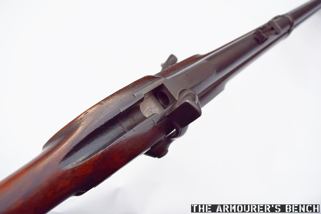
The rifle with its trigger guard rotated forward and its breech open (Matthew Moss)
Like the earlier Ferguson rifle, which drew heavily on earlier screw breech designs, this rifle has a rotating trigger guard which acts as a lever to unscrew the breech. Rotating the trigger guard drops a rectangular breechblock and opens the action. Unlike the Ferguson the threaded piece does not act as the breech plug itself, instead the separate breech block takes the brunt of the cartridge ignition.
The rifle with its breech open (Matthew Moss)
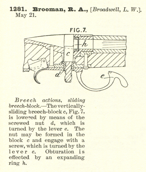
Broadwell filed the patent believed to correspond to this rifle first in Britain, in May 1863, and subsequently in the US in August 1865 (US #49583). The patent protected the breech action and depicts what Broadwell described as a ‘screwed nut’ below a rectangular vertically sliding breech block. This idea of a sliding breech-block builds on his earlier patent for a sliding cannon breech.
Broadwell’s UK patent, dated 1863 (UK Patent courtesy of Research Press)
In Britain, Broadwell used Richard Brooman, of Robertson, Brooman and Company, as a patent agent. At the time Brooman’s company offered a service by which he acted as the inventor’s deputy and was listed as the patent holder, while the inventor was listed as the ‘communicator’. The service cost the not insignificant sum of £45 (at the time a labourer could earn just 3 shillings 9 pence per week – or 15% of £1 – that’s just under a year’s average wages). This initial sum covered the patent for three years. It is likely Broadwell employed an agent because at the time he was living in St Petersburg in Russia, undertaking negotiations with the Russian Government to establish Gatling Gun production. Brooman was also the editor of The Mechanics’ Magazine, a Victorian science and industry journal.
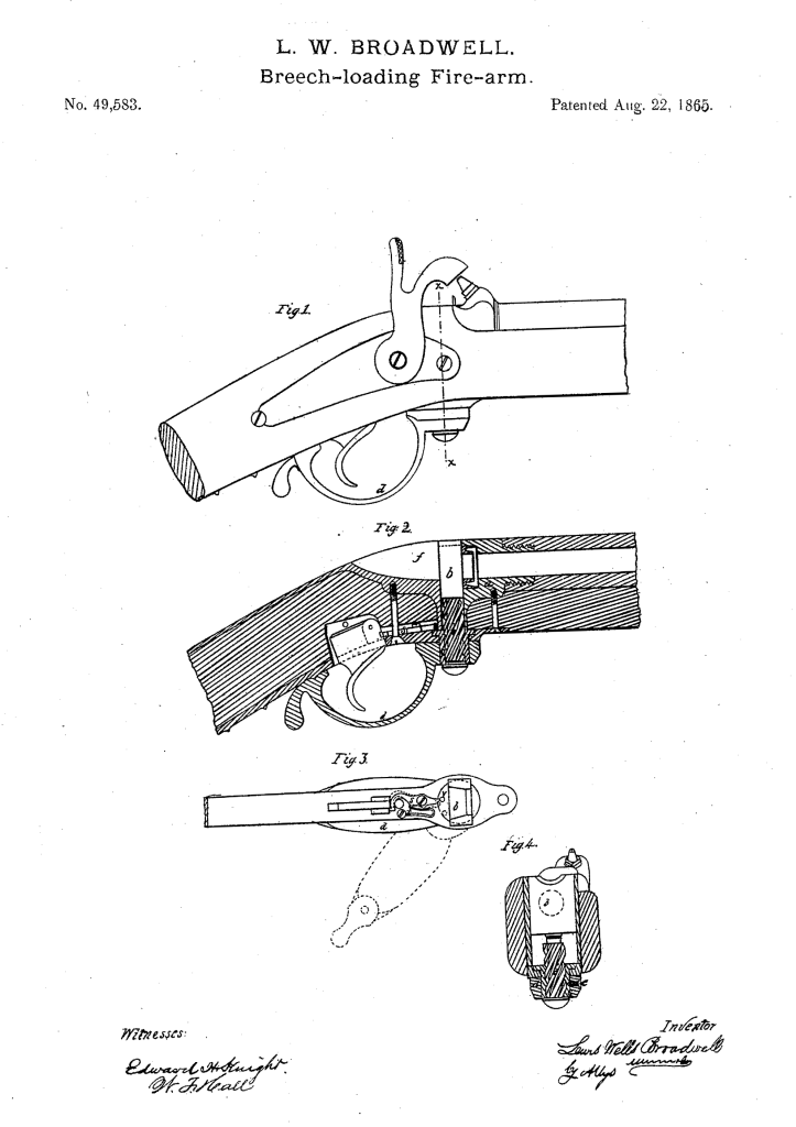
Broadwell’s slightly different 1865 US patent which is also similar to the rifle we are examining (US Patent Office)
The breech plug has a screw thread with a very wide pitch with flat crests. Broadwell’s US patent describes the breech plug as having a ‘three to six threaded screw’. The breech blog falls enough to allow loading after turning the lever around 200-degrees – ensuring a rapid action. Interestingly the British patent shows the lever not attached to the base of the screw plug but instead shows it at the mid-point of the screw. This may be an error in the drawing. It seems that if the rifle we are examining is a Broadwell prototype it was decided to simplify the action by attaching the lever at the base of the plug.
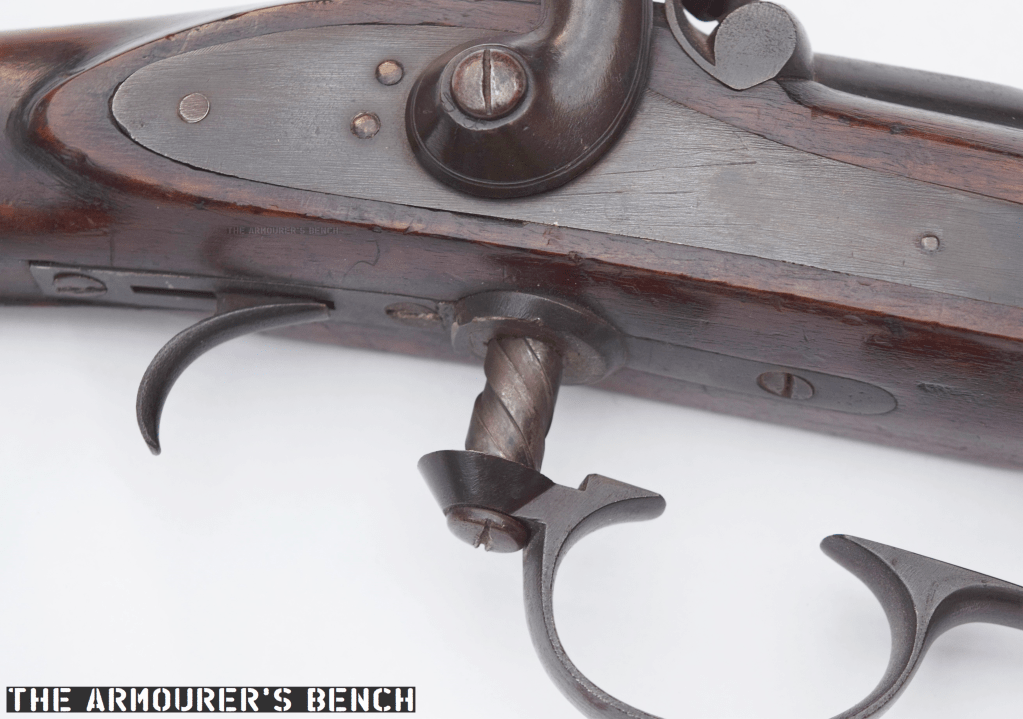
A close up of the rifle’s trigger guard and screw (Matthew Moss)
This rifle itself, has no markings whatsoever, not even range markings on the rear sight. Typically rifles of this period would at least have a marker’s or patent holder’s mark on the barrel or lock plate. This suggests that the rifle is either unfinished or more likely a prototype which did not require extensive markings.
The rifle’s unmarked rear sight (Matthew Moss)
The breechblock is not blued and is possibly case hardened. Much like the Ferguson, and other earlier screw-breech rifles the trigger guard also acts as the breech lever. Which with a rotation of approximately 200 degrees, descends enough to open the breech and allow access to the chamber. The threaded screw is around 0.5 in (1.2cm) thick and acts on a rectangular breechblock which sits above it. This basic layout matches Broadwell’s 1863 UK patent.
The rifle with its breech partially closes, there is no method of extraction indicating it used a combustible cartridge (Matthew Moss)
The rectangular shape of the breechblock ensures a strong action as it butts up against a pair of narrow shoulders (about 1mm in width) at the rear of the receiver. The rifle has a two band stock and a cleaning/ramrod which indicates a military-style rifle but interestingly, there is no obvious provision for fixing a bayonet.
The rifle is believed to be chambered in a cartridge using a .451 Westley Richards projectile. There is no method for extraction so we can safely assume the rifle used a combustible cartridge, ignited by a percussion cap rather than a self-contained metallic cartridge. Interestingly, the UK patent also suggests the use of a “tubular magazine… formed in the hammer, containing self-acting feeding apparatus for supplying ignition wafers or patches to the nipple.” This is not mentioned in the later US patent and the rifle we’re examining has a conventional capped percussion lock.
A close up of the Note rectangular breech with the action closed (Matthew Moss)
The US patent describes a ‘mechanism to prevent the gun from being fired when the breech is open’, this is formed by a lever which disengages with the trigger when the breech lever is rotated. There is a small leather flange in the base of the stock where the screw ascends and descends, this prevents the ingress of dirt and also acts to keep the screw clean.
Left profile of the rifle (Matthew Moss)
Compared to Patrick Ferguson’s action Broadwell’s design simplifies the breech plug using a simpler to manufacture rectangular breechblock and a thinner screw plug. The use of a self-contained cartridge would have sped up loading but the need to cap the rifle’s nipple was still a limiting factor. The screw breech concept became increasingly obsolete with the introduction of self-contained metallic cartridges with integral primers as well as the introduction of faster actions including bolt actions, falling block actions and toggle-locked lever actions.
Lewis Broadwell was born in Cincinnati, Ohio, on 18th July 1820. He is perhaps best known for his drum magazine design for the Gatling Gun. The Broadwell Drum consisted of a series of single stack, gravity assisted magazine columns arrayed around a central pivot point. These columns held between 15 and 20 rounds depending on calibre and typically there were 16 columns of ammunition. Broadwell patented the drum’s design in December 1870. It was used extensively during the 1870s by a number of militaries around the world, including by the British Army. Broadwell was granted his last patent in 1876 and died, aged 86, in May 1906.
Special thanks to the Hayes collection for letting us take a look at this very interesting rifle. Thanks to David over at the Research Press for help finding the patent and to John Walter for his help finding information on Broadwell himself.
In late 1944, a platoon of Canadian sappers built an intriguing in-field adaptation to a Universal Carrier (sometimes known as Bren Gun Carrier) – they developed a PIAT Carrier.
The 16th Field Company, Royal Canadian Engineers were attached to the 3rd Canadian Division during operations in northwest Europe. Each Canadian division had a Divisional Royal Canadian Engineers Group attached to it, made up of several field companies. In November 1944, the 16th Field Company, RCE was located near Nijmegen.
The ‘PIAT Carrier’ (Library and Archives Canada)
The experiments which led to the PIAT Carrier were embarked on after the division’s commander, Major General Daniel Spry, put out a directive for ‘harassing weapons’ to be developed. The interesting adaptation was somewhat reminiscent of a miniature Soviet Katyusha or Commonwealth Land Mattress. While similar in concept to these multiple rocket launchers, it is important to remember that the PIAT isn’t a rocket launcher – but a spigot mortar.
Loading a Land Mattress multiple rocket launching system (IWM)
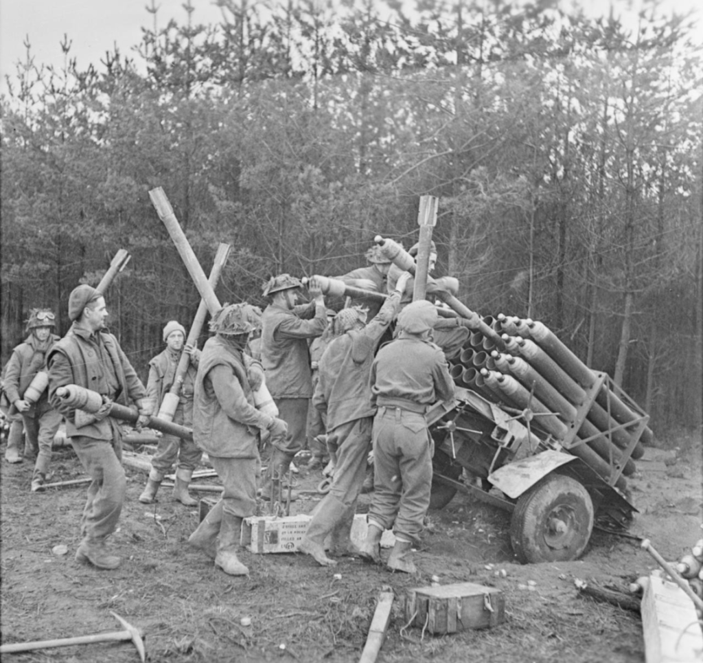
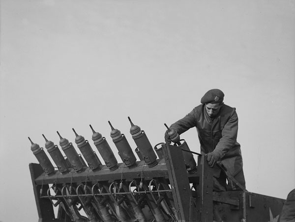
The Canadian engineers mounted the PIATs in two rows at an obtuse angle at the rear of the Universal Carrier, presumably for use in a limited bombardment role. The idea behind the outfitting of the Carrier appears to have been to utilise the PIAT in its secondary, indirect role as a mortar, perhaps for fire against buildings or to harass enemy positions. From photographs taken in the field we can see that the engineers of 16th Field Company fixed the PIATs into a wooden frame at the rear of the Carrier, they appear to have had their monopods removed, but some still appear to have their slings fitted.
Developing the PIAT Carrier
From further research and some digging through the 16th Field Company’s War Diaries, I found reports on the adapted carrier and even some diagrams showing how the bombs landed. The diaries also reveal that the Universal Carrier was not the first vehicle the PIATs were mounted on – the first tests were carried out on a truck.
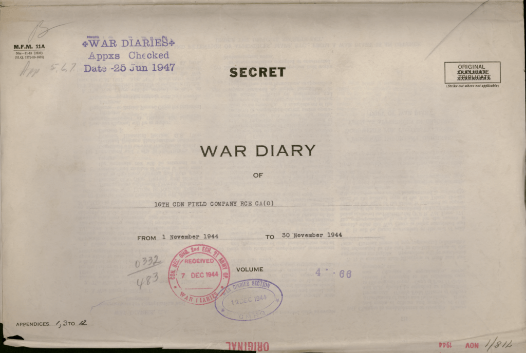
Front Cover – 16th FC, RCE, Nov. 1944 War Diary (Library & Archives Canada)
In the war diary we get the first mention of the PIAT battery in the entry for the 15th November 1944. It reads:
“The GOC directed that each arm of the service should be prepared to devise some means of harrassing the enemy during the holding role of the Div present area and to act as a counter-measure to the Moaning Minnies [Nebelwerfer] employed by the Germans. The ORE decided that the Sprs could make use of the 24 PIAT’s held by the C in Div Engre. The tentative Idea being that these be mounted on a veh, or two vehs, that they be fired mechanically and possibly simultaneously with a multiple mortar effect. Lieut. Cameron and No. 1 Plattoon [sic] were given the task, experiments to be carried out tomorrow for this purpose all PlATs and ammunition were called into this Company from Div Engrs.”
The next day on the 16th November the diary recorded:
“Lieut. Cameron made a number of tests with his PIAT platoon In conjunction with the N.S.R. and found that the maximum range that could be attained was 300 yds. Maj Main will discuss this matter with CRE tomorrow.”
Then several days later on the 19th November:
“Lieut. Cameron gave a demonstration of the capabilities of the PIATs used to fire with a mortar effect, 18 PIATs were mounted in racks on one vehicle at an angle of 45 degrees and fired simultaneously. There was no jar to the vehicle, Max range obtained was 300 yds against the wind and 400 Yds with the wind, detonation of salvo was all within one second of time and covered an area 25ft in length by 15ft width.”
This short report concluded by explaining why the PIAT Carrier may not be field practical, noting that “The plan is not practicable at present as areas of firing are not available that would permit the vehicle moving up to 300 yds from target before firing.”
The first major test is described in a report dated 21st November. A total of 22 PIATs were available to Lieut. Cameron’s platoon. They mounted 18 PIATs in racks on the bed of a Ford Canada 60 cwt (60 hundredweight – 3 ton) truck, with the remaining 4 as spares.
The report explains that steel wasn’t available so wood was used for the racks. Which they also believed would have a “cushioning effect serving to shield the truck to some extent from the shock of recoil.”
The 18 PIATs were arranged in three rows of six PIATs with PIATs spaced 1 foot apart next to one another, with four feet between each row. The PIATs were angled at 45-degrees by a wooden plank attached to the side of the truck bed with the butt of the weapon bolted down under wooden struts.
With no photos of the ‘PIAT Truck’ here’s a quick fun artists impression (Matthew Moss)
To fire the weapons rods were run along the rows aligned with the weapons’ triggers with bars of 1/2in steel running back between each one and back towards the font of the truck where the operator was stationed. The report describes this set up as ‘satisfactory’.
In the first test all three rows of PIATs were fired at the same time. The report’s findings note that in the first test all but one of the weapons fired, the bombs were in the air for an estimated 4 to 5 seconds and the time between the first and last bombs striking the ground was approximately ½ to 1 second.
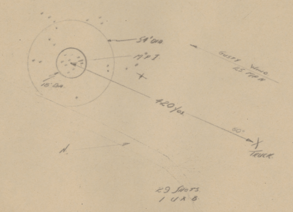
The blast radius of the individual bombs is noted as 5 feet with 6 to 9 inches of penetration through gorse and sandy loam soil. The range was found to be 310 yards against the win and 400 yards with it. The wind was noted to be travelling as 20-25mph. From the diagrams accompanying the report we can see that the beaten zone had a maximum diameter of approximately 54 to 60 feet. With a mean point of impact around 15 to 18 feet wide.
A fall-of-shot diagram from the November RCE report, 16th FC, RCE, Nov. 1944 War Diary (Library & Archives Canada)
The second test saw the sappers fire two full salvos to test how quickly the rig could be reloaded. The reload time between salvos was recorded as 1min 20seconds. The second salvo saw 6 of the PIATs fail to fire due to a mechanical failure when one of the trigger rods broke. The extreme range achieved during this second firing was 420 yards with the wind.
During this first field test of the truck mounted system, a total of 65 bombs were fired and only one failed to explode down range. The racks were strengthened and the trigger rod repaired, it was also concluded that the racks could be spaced closer together without “effecting the pattern of the beaten zone” down range.
There is no further mention of the testing in the war diary during November but progress definitely appears to have been made, an entry on the 16th December notes:
“The use of PIATs mounted on a vehicle has had further experimental trials, 15 PIATs have been mounted on a Bren Carrier by this unit and a trial shoot was held today, Against a slight wind a range of 310 yards was attained with the area of burst covering 25 ft deep and 50 ft wide, no recoil was felt in the carrier.”
The last mention of the PIAT Carrier comes on 30th December:
“The carrier mounted with 15 PIATs was on trial during the afternoon before an audience consisting of the GOC and Officers of the Div. All visitors were impressed by the display. A range of 350 yds was attained and the accuracy on target was good.”
There are no further mentions of the PIAT carrier in the diary. It seems that development of the idea didn’t progress into 1945, by early February, the 16th FC RCE were involved in Operation Veritable. It appears that the operational requirement no longer existed.
Lets take a closer look at how the adaptation was done. From the available photos, which were probably taken in mid-December 1944, we can see the trigger bar that was passed through the trigger guards of each of the PIATs, with the bar resting at the base of the trigger, it is unclear from the available photographs but this may have allowed the weapons to be fired either by row or all together.
Close up photograph of the racks holding the PIATs – note the trigger bars, wooden frames and the PIATs’ white in-direct fire aiming lines (Library and Archives Canada)
The sappers have built a wooden platform onto the back of the carrier with welded metal brackets holding the pieces together. The PIAT’s are held between two wooden cross pieces that have been bolted together. There’s a strip of metal running around the edged of the wooden frame that has been twisted 90-degrees and then welded to the carrier. It is also worth noting that all of the PIAT’s have had their butt pad covers removed and the feet of the PIATs’ rear end caps have been secured with a pair of brackets either side.
The PIATs in their racks (Library and Archives Canada)
In the photograph above we see all of the PIAT’s held in their racks with their sights folded down, slings still attached, and we get a good view of the white indirect fire aiming lines. At the bottom of the photo we can see a trigger bar which when pulled appears to pull the triggers of the whole row at once. As an aside, note that the carrier has a ‘crooked’ Commonwealth allied star – to differentiate it from the US allied stars which were aligned with their top point at 12 o’clock
It appears that the battery of PIATs was aimed by reversing the Carrier towards its target, that would certainly have been challenging and a fairly dangerous task given the relatively short range of the PIAT even when used as a light mortar.
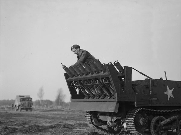
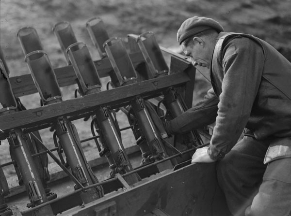
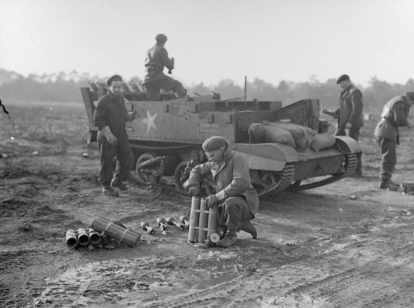
From this photograph below, of a Canadian sapper loading the PIATs, we can see all of the spigot tube stoppers dangling on their chains. The sapper is loading the bomb from the front of the bomb support tray and has angled the tail up to slide the projectile loading clip into the projectile clip guides on the face of the PIAT.
Loading the PIATs (Library and Archives Canada)
It also appears that sandbags are being used as a counterweight at the front of the carrier. The combined weight of the PIATs and their bombs (about 555 lbs) as well as the weight of the frame would have been considerable.
In the final photograph below we see the sappers preparing the battery to fire with a sapper in the foreground removing bombs from three bomb carriers. While in the background on the right we can see another sapper carrying bombs forward from another set of bomb carriers. I would guess that it was perhaps decided to mount 15, rather than an even number, PIATs as the bomb carriers held three round each – with 5 bomb carriers needed to reload the battery of PIATs.
Readying the PIAT Carrier for testing (Library and Archives Canada)
While sadly we don’t have any footage of the test we’re very lucky to have this selection of brilliant photographs courtesy of the Library and Archives Canada. It would seem that the limited range of the PIATs made the concept of a PIAT Carrier too impractical to field – but a maximum range of 400 yards may have offered some interesting tactical options for dealing with defended buildings or field works. Perhaps need for a response to the enemy Nebelwerfers was answered by the introduction of the longer ranged, harder hitting Land Mattress. Despite this the ‘PIAT Carrier’ is a fascinating piece of resourceful engineering – an innovative, field-expedient adaptation that brought together two classic bits of British and Commonwealth kit – the PIAT and the Universal Carrier.
In this episode we examine the Sidney Lumet classic ‘The Hill’ which sees standout performances from a brilliant cast of character actors and the late, great Sean Connery. The film follows a group of British Army prisoners who are pushed to their breaking point in a military prison under the baking desert sun.
The podcast is also available on other platforms and apps – find them here.
Here’s some stills from the film:
Be sure to follow us on Twitter, @FightingOnFilm, and let us know what you thought of the episode and if you’ve watched the film.
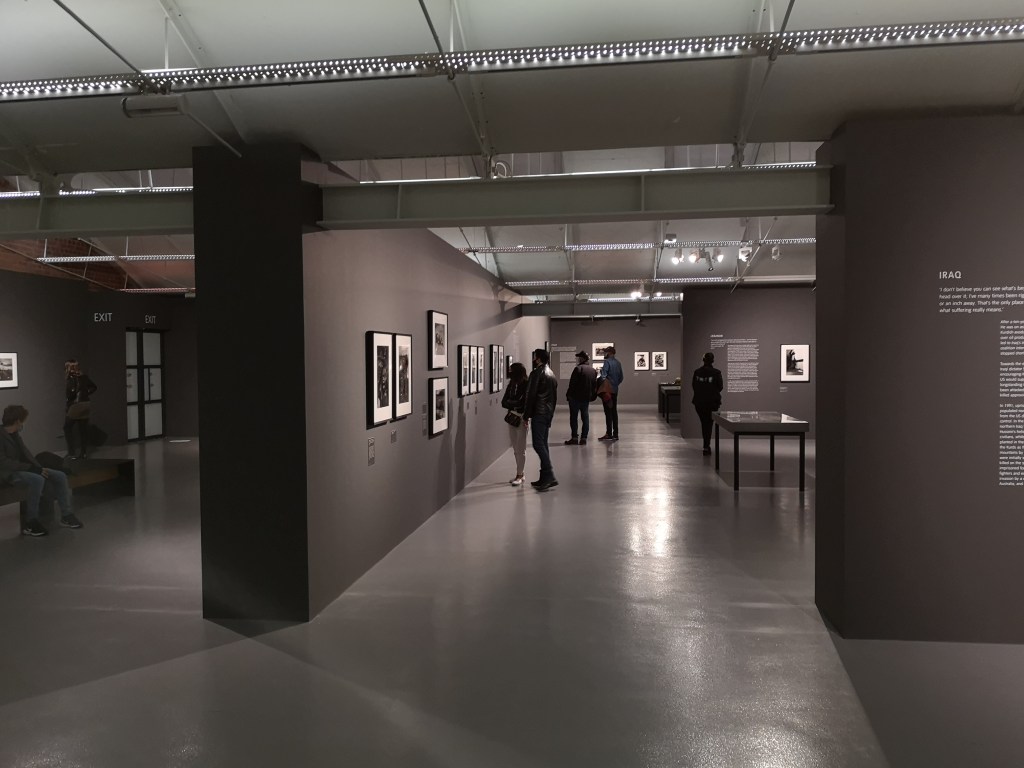
I recently had the pleasure of visiting Tate Liverpool’s Don McCullin exhibition. McCullin is one of my favourite photographers not just for his incredible combat and conflict photography but also for his street photography which focuses on the hardships and lives of people.
Inside the exhibition (Matthew Moss)
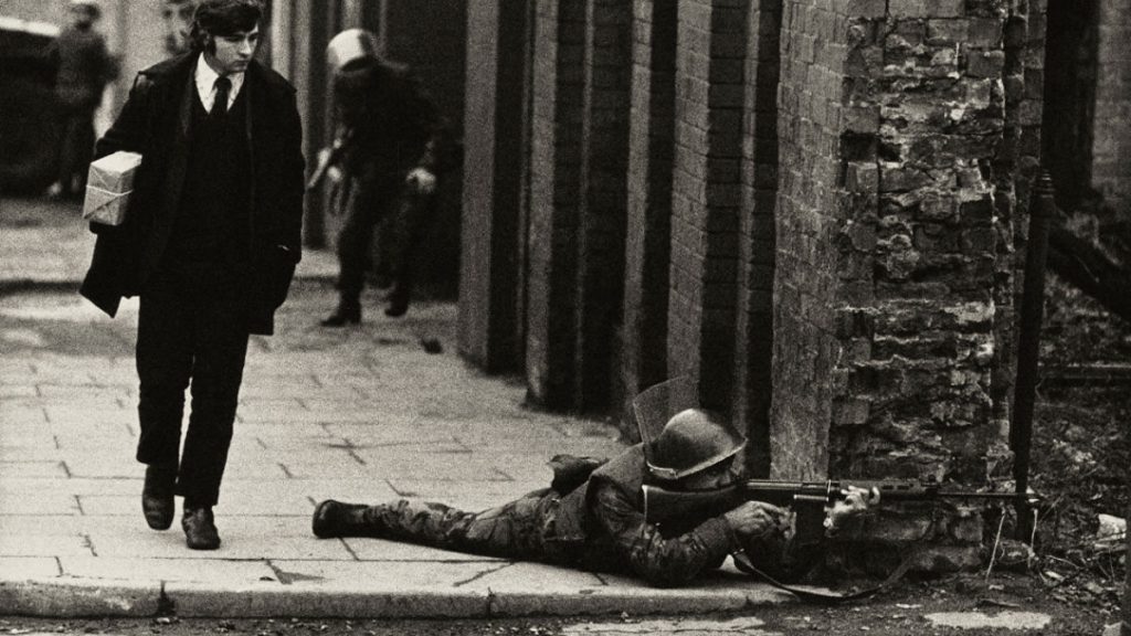
McCullin, now 85, is probably best known for his photographs of conflict, including iconic photographs taken during the Battle of Hue, and his coverage of fighting in Northern Ireland, Crete, Cambodia, Lebanon and throughout Africa. His work covering famine in Ethiopia and the war and refugee crisis in Bangladesh evoke an immense amount of pathos.
Northern Ireland (McCullin)
The Tate’s exhibition is a well deserved retrospective that charts McCullin’s career from its beginnings through to the present – with him most recently travelling to Syria in 2016.
This short video includes some photographs of the exhibition which covered an entire floor of the gallery with each of the conflicts McCullin has photographed covered in chronological sections.
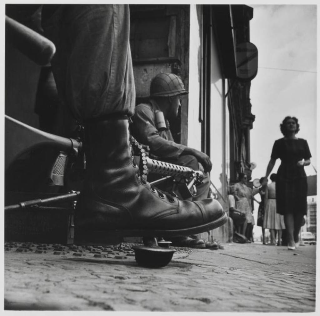
Checkpoint Charlie, with an M1919A6 (McCullin)
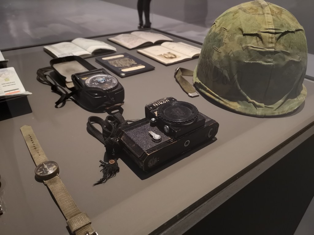
The exhibition is interspersed with collections of magazines which shows how some of his work was originally published by a wide range of magazines and publications. Perhaps the most interesting artefacts on display were a number of McCullin’s personal items including a US Army helmet, a light meter, a watch, passports, a compass and a 35mm Nikon F camera which apparently was struck by a 7.62x39mm round while in Cambodia in 1970.
Some of McCullin’s personal items used on assignment (Matthew Moss)
One thing I did find disappointing as a photographer myself was that the information with each photograph didn’t include what medium – film (35mm or 120) or DSLR, he took the photograph in. McCullin is an immensely skilled photographer with an amazing grasp of composition and technique while being able to capture highly emotive images. As he’s not only a photographer but also an expert photo developer, it would have been nice to have some of this more technical information next to each photograph. Regardless it was an immensely enjoyable exhibition which put into perspective the sheer breadth of McCullin’s work.
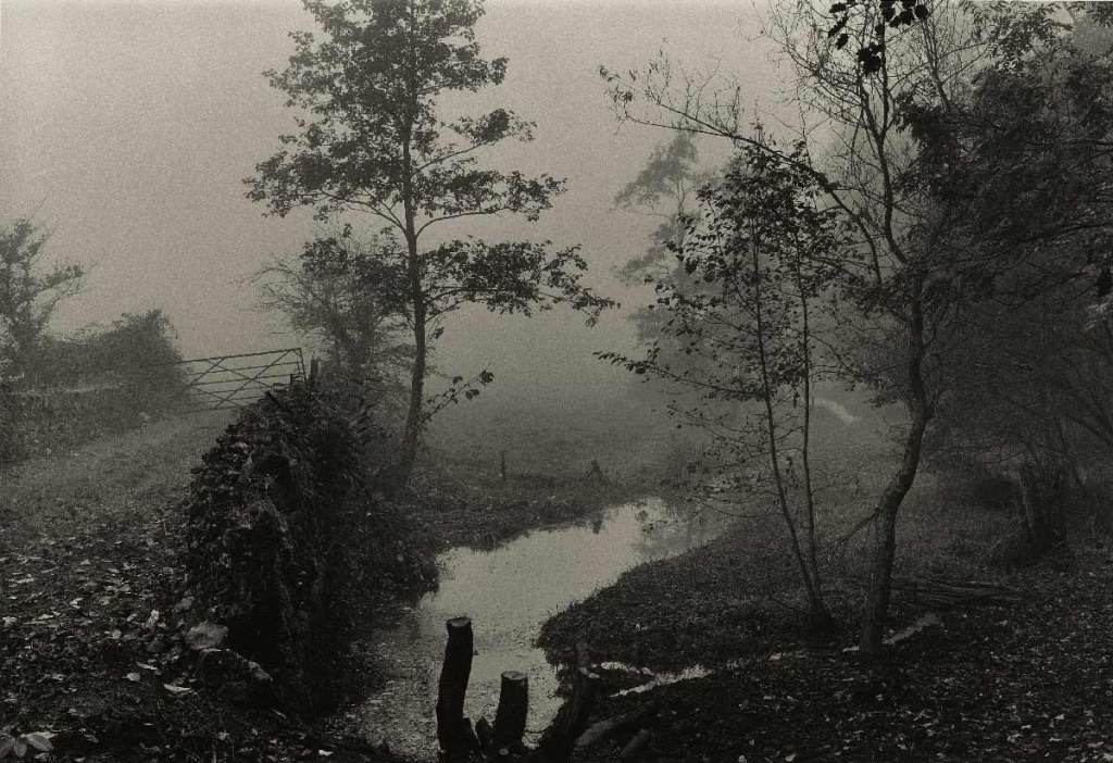
One of McCullin’s many photographs of poorer, industrial UK towns & cities (McCullin)Cyprus 1964, (via Tate)One of McCullin’s more recent foggy landscapes (McCullin)
Without doubt McCullin’s life’s work has affected him, seeing so much through the lens of your camera and being largely helpless to help people suffering is something McCullin mentions in a number of interviews and it is a thread in the narrative of the exhibition. McCullin’s most recent work – a series of strikingly moody foggy landscapes is described as being solace from his work documenting conflict and a way of dealing with his experiences.
Find out more about the exhibition here. It runs until the 9th May, 2021.
You can find some of McCullin’s best photographs here.
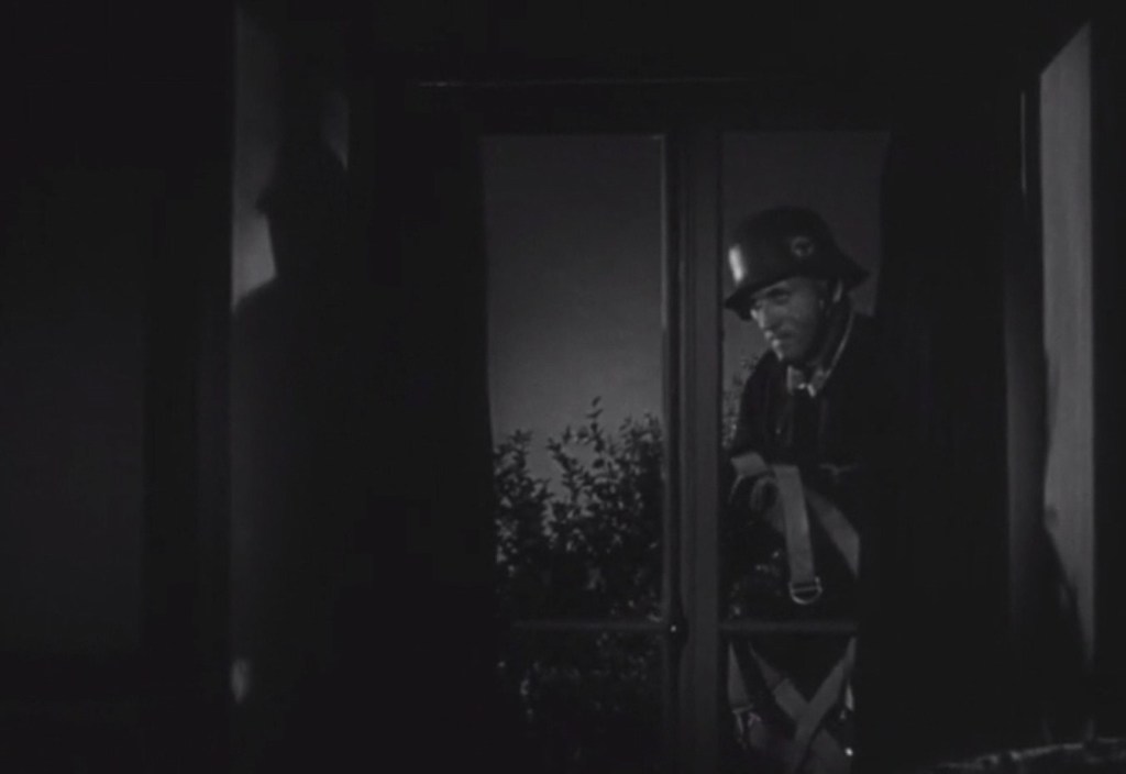
Join us as we discuss the 1940 Ministry of Information film, Miss Grant Goes To The Door. Directed by Brian Desmond Hurst (of Theirs Is The Glory fame) it follows the plucky Grant sisters as they foil a Nazi fifth columnist as German paratroops invade England!
Here’s some stills from the film:
You can watch the film (for free) on the Imperial War Museum‘s site, here.
Be sure to follow us on Twitter, @FightingOnFilm, and let us know what you thought of the episode and if you’ve watched the film.
The podcast is also available on other platforms and apps – find them here.
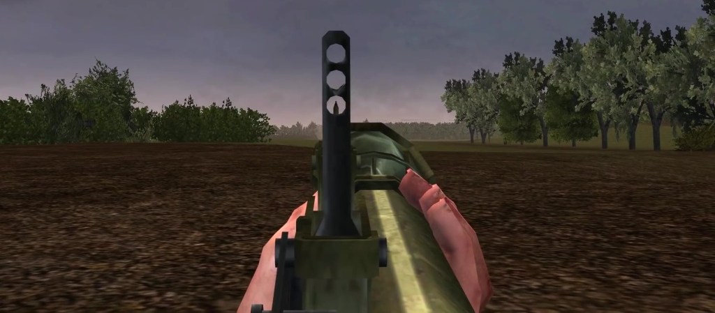
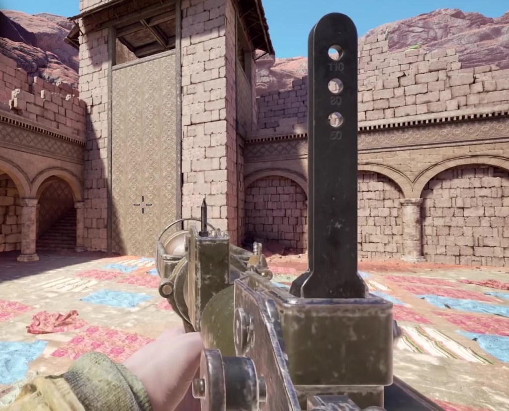
In this video we have some fun and look at portrayals of the PIAT in various games over the last 20 years. We’ll look at the size, shape and physical characteristics of the models, how they function in the game and the animations and sound effects of them in action!
We start off with 2002’s Medal of Honor: Allied Assault and run all the way through to 2020. I’ve only had the chance to play a handful of these games so I can’t comment too much on how accurately the PIAT’s effectiveness is depicted in each game but I can definitely comment on how the models look! There is lots to look at and some do a surprisingly good job.
There are some very basic, some very wrong and some surprisingly accurate representations of the PIAT in the various games we look at. But really it’s just good to see it represented in games in the first place!
Thank you to Tigerfield for the use of some of his footage used in the video.