The 1890s were one of John Browning’s most prolific periods, during which he developed a host of firearms which would never actually see production. Here, we’re lucky enough to be able to examine one of those prototypes that were never produced. Dating from 1892, this rifle departs from Browning’s earlier lever-action rifle designs in a number of interesting ways. Perhaps the most interesting aspect of the design is its use of en bloc clips, instead of the tube magazine traditionally used by Winchester’s repeating rifles. John Browning, and his brother Matthew, filed the patent covering the design in June 1892.
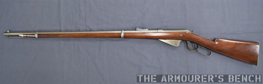
Right side of the rifle, note its ‘musket’ configuration (Matthew Moss)
The rifle is in what is typically referred to at the time as a ‘Musket’ configuration, signifying that it is a military long-arm. It has a long 32.5 inch barrel, which is held in place by two barrel bands. Overall the rifle is around 50 inches in length and weighs just over 9lbs. The rifle is chambered in a .30 calibre cartridge, likely the then new .30-40 Krag round given its proposed market. It has a ladder-style rear sight with range graduations from 100 to 1,000 yards.
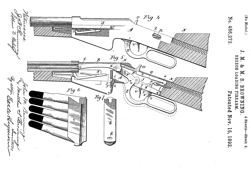
Browning’s patent drawing showing the rifle’s action (US Patent Office)
Okay, let’s take a closer look at the prototype. During the 1890s Browning experimented with a series of magazine systems including an en-bloc clip system. This rifle uses a 5-round magazine which is fed from an en-bloc clip. The idea of an en-bloc clip was relatively new with Ferdinand Mannlicher patenting the idea in the 1880s and using it in his Model 1886 and 1888 rifles. It is unclear if Browning was familiar with Mannlicher’s system but the two are very similar. If you’re unfamiliar with en bloc clips it means that the cartridges are loaded into the weapon in the clip rather than stripped from the clip.
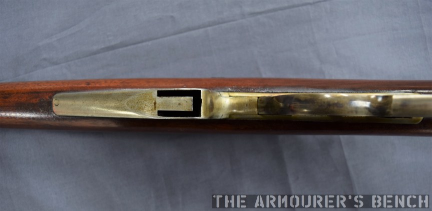
A look at the ejection port for the en-bloc clip (Matthew Moss)
Browning’s prototype holds five rounds in its clip, which from patent drawings we can see was not reversible. Sadly, we don’t have an example of Browning’s clip to examine but his 1892 patent (see above) gives us a good idea of what it would have looked like. It clearly has a cut at the top of the clip which appears to have been used to help guide the round up into the chamber.
Rounds were pushed up into the action by a follower arm which was actuated by a v-spring located at the front of the magazine housing. The bottom of the fixed magazine housing has a cut-out corresponding to the clip to allow it to fall or be pushed clear by a new clip once it was empty.
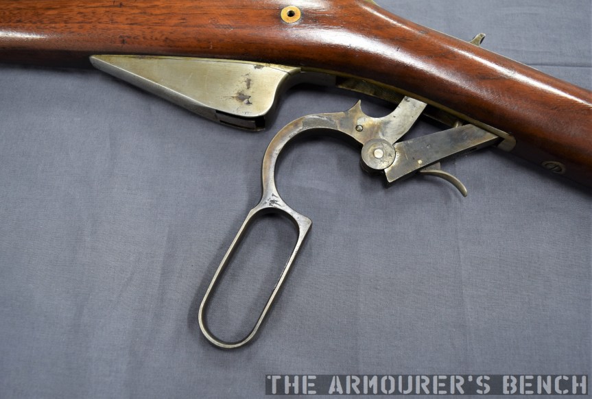
The rifle’s lever fully-forward with its action open and striker cocked (Matthew Moss)
The rifle also departs from the traditional hammer system and uses a striker-fired action. From the patent drawings we can see how the rifle’s striker worked, with a coil spring extending into the stock and a sear holding the striker to the rear. The striker is made up of two pieces with the striker hitting a long firing pin inside the bolt.
The striker has, what the patent refers to as, a ‘thumb piece’ to enable re-cocking and to indicate if its cocked or not. The striker was cocked by the cycling of the lever and held in place by the trigger sear.
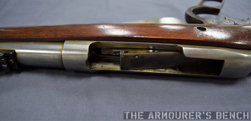
A view inside the action with the bolt partially retracted before it moves down and back into the rifle’s wrist (Matthew Moss)
The lever was held in the close position, preventing out of battery discharges, by what Browning’s patent calls a downward-projecting dog, which projected through a small hole in the trigger assembly link and locked into a catch in the front of the lever loop.
The use of a striker, rather than an exposed hammer, allows the rifle bolt’s travel to be enclosed rather than have the bolt project out of the rear of the receiver, as in previous Winchester lever-actions, we can see that this rifle’s bolt slides back at an angle partially down into the wrist of the stock. This is arguably more ergonomic and potentially helps to prevent ingress of dirt.
The first half of the lever’s travel pulls the bolt to the rear, while the second part cocks the striker. An arm extending from the lever pushed the bolt rearward until the trigger sear was engaged. In order to give the lever enough throw to open the action far enough to allow a round to be loaded the trigger mechanism has to be pivoted out of the action, much like the earlier Winchester 1886.
The bolt has a pair of trunnions which project from the sides of the bolt, these run inside longitudinal grooves either side of the receiver, while the rear of the bolt is free to angle up and down as it cycles. The action is locked by the rear of the bolt secured against the rear of the receiver, rather than with a rising locking bolt.
Left side of the rifle (Matthew Moss)
During the period Browning was also working on other lever action and, even more unusual, so-called pull-apart actions as well as various magazine types including a revolving magazine, stripper-clip box magazines and of course as we’ve already seen a detachable box magazine-fed rifle. The 1890s were a truly prolific period for Browning.
The design was purchased by Winchester and the Brownings’ patent was granted in November 1892. The gun, like many of Browning’s other designs of the period, never saw production. Making this rifle a rare one-of-a-kind prototype. It’s an elegant design and the action is smooth. When Winchester did finally seek to produce a military lever-action they chose another of Browning’s designs which retained his traditional rear-locking bolt, which became the Model 1895.
This rifle is a unique prototype and it was an honour to examine it. It’s now on display at the newly refurbished Cody Firearms Museum at the Buffalo Bill Centre of the West. Our thanks to the museum for allowing us to film items, like this one, from the museum’s collection.
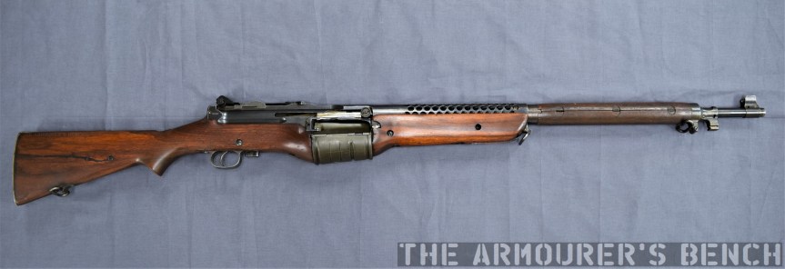
The Johnson is already one of the 20th century’s most interesting military rifles, in terms of both design and history, and this rifle, serial number R-14, is perhaps even more interesting. Johnson’s military rifles were initially designated the Type R – for rotary magazine, it was the ‘R’ serialised rifles which were used during US military testing in 1938-40. We are most familiar with the classic handguard-less appearance of what became known as the Johnson M1941. Few examples of a Johnson with a handguard survive.
Right-side view of the R-14 with original optional extra handguard (Matthew Moss)
The rifle was developed by Melvin Johnson, a USMC Reserve Captain, in the mid-1930s, Johnson began work on the rifle just as the M1 Garand was adopted. Johnson was granted his first patent protecting his rifle in September 1937. His rifle was tested in 1938-39 by US Army Ordnance but advanced no further than testing. Johnson lobbied politicians leading to a bill being introduced in an effort to have Johnson’s rifle adopted. On May 29th, 1940 the US Senate’s Military Affairs Committee met with Johnson and military representatives to discuss the rifle and the Bill which had been proposed, S.3983, to ‘Provide for the Adoption of the Johnson Semiautomatic Rifle as a Standard Arm of the Military’. The bill, however, led nowhere and the M1 Garand’s introduction continued.
A Johnson M1941 (Courtesy of Rock Island Auction Company)
The handguard fitted to R-14 was actually an optional extra offered by Johnson Automatics. It appears to have been an attempt to address one of the main concerns raised by the US military – the Johnson’s unsuitability for bayonet fighting. As the rifle uses a short-recoil operated action the barrel recoils about ½ inch on firing, this means that the weapon’s barrel isn’t actually fixed in place meaning when the bayonet was used the barrel moves backwards ½ inch when it contacted something or someone with enough force.
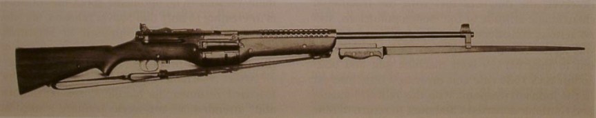
A Johnson R-Type Rifle fitted with hanguard & M1905 bayonet (Johnson Automatics Brochure)
From the Senate Committee hearing we know that there were real concerns about the rifle’s bayonet fighting characteristics. With US Army Ordnance noting that “this rifle is very poorly suited to bayonet fighting.” Noting that the exposed barrel was too narrow to grasp properly and was also un-insulated if the barrel was hot from firing. The non-fixed, recoiling barrel was also highlighted as another ‘deficiency’. Major Grant Schlieker, the Infantry Liaison Officer at the Aberdeen Proving Ground, shared similar concerns. In addition to concerns about the lack of handguard to grasp when bayonet fighting he noted in his statement that during their testing the Johnson has struggled to cycle properly when fired at a depressed angle with a bayonet fixed and that striking something with the bayonet hard enough lead the rifle to extract and eject a chambered round.
A closer look at the handguard, also note the addition of a stacking swivel just behind the bayonet lug (Matthew Moss)
Johnson refuted these concerns by stating that the barrel was exposed with good reason so that it could cool rapidly, suggesting that enclosed barrels like the Garand’s became too hot to grasp after sustained firing thus also making bayonet fighting difficult. Johnson also noted that a ‘Johnson Sword Bayonet’, which extended forward under the barrel from the Johnson’s normal forend had been developed to address the problem but the ergonomics and usefulness of this terrifyingly long bayonet are unclear.
An R-type rifle fitted with the extremely long Johnson Sword Bayonet, note the large lug beneat the barrel, extending from the rifle’s handguard (Johnson’s Guns – Canfield)
You would imagine that a fixed, full-length stock with the barrel recoiling inside would have been a more elegant solution allowing the bayonet to be fixed to a nosecap rather than the barrel. But it would seem that Johnson was passionate about having the exposed barrel to allow cooling.
It is worth noting that the bayonet issued with the M1941 was the lightweight spike-type, developed in order to elevate potential issues with cycling while the bayonet was fixed.
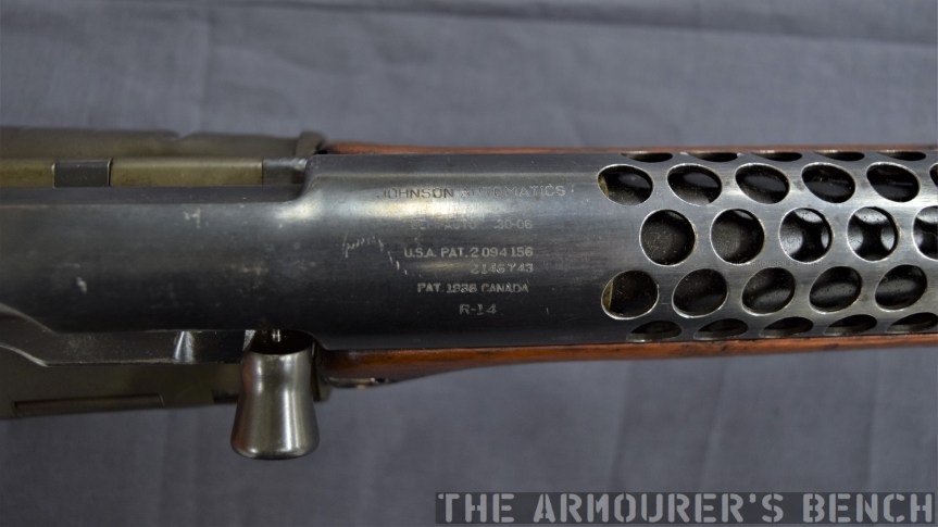
A close up of R-14’s markings (Matthew Moss)
A proponent of the rifle, USMC Captain, George Van Orden (who commanded the Rifle Range at the Marine Corps Barracks at Quantico) went so far as to claim that the recoiling barrel had a positive impact on bayonet fighting “a recoiling barrel can provide extra thrust in bayonet fighting, as in the case of a boxer who in striking a blow, at the moment of contact… straightens his elbow smartly.” The Johnson Automatics manual for the rifle even claimed that testing against pine board showed that “the short recoil of the barrel actually tends to increase the penetration of the bayonet.”
From the May 1940 Senate hearing records we know that the R-14 wasn’t always fitted with the barrel with the enclosed handguard. It was one of several rifles used by Captain Van Orden to test the rifle’s accuracy and there is not mention in his account of the rifle’s barrel being shrouded with a handguard. This isn’t too surprising as the Johnson’s barrel can be removed easily and readily swapped out.
Close up of the guide collar at the rear end of the handguard (Matthew Moss)
The bayonet lug appears to be designed to mount a US Army M1905 bayonet, the sword bayonet issued with the M1903 Springfield. The assembly also has a sling swivel. R-14’s barrel is 23.75 inches long – this is a little longer than the standard 22 inch barrel, but 24 inch barrels were an option offered by Johnson Automatics. The round wooden grips panels are held in place by three pairs of slips and the nosecap and the guide collar.
Other than the forend this rifle also has a slightly different style of rear sight compared to the M1941 production rifles. The receiver markings are also simpler with calibre, patents and a plain maker’s mark, with serial number at the bottom.
A closer look at the handguard’s nosecap and bayonet lug (Matthew Moss)
The addition of the handguard certainly does allow a greater area for the forward hand to grip the rifle. But what is less clear is the effect the added mass of the handguard, nosecap and bayonet (when mounted) had on the cycling of the gun. Logic would suggest that any weight added to the barrel would slow the its travel and potentially cause reliability issues. The handguard and bayonet would have added at least 2lbs. Sadly, I’ve been unable to find any documentary evidence to tell us how the rifle functioned with the forend. No mention of the handguard is made during the Senate committee hearing but a ‘fixed-type’ bayonet is mentioned which is described as “not in any way interfering with the recoil of the barrel.” This was presumably referring to the long Johnson Sword Bayonet. Despite them being offered as an official option it is fair to presume that the rifle would have struggled to operate properly when fitted with the handguard.
When the Johnson finally entered production it was with an exposed barrel as he intended and R-14 remains one of the few examples to have the Johnson’s optional handguard.
Many thanks to the Cody Firearms Museum for allowing us to examine and film the rifle and take a look at a rare example of the Johnson Automatics optional extra handguard.
Military Handbook of the Johnson Semi-Automatic Rifle (1939)
The Johnson Semiautomatic Rifle: Hearing Before the Committee on Military Affairs, United States Senate, Seventy-sixth Congress, Third Session, on S. 3983, a Bill to Provide for the Adoption of the Johnson Semiautomatic Rifle as a Standard Arm of the Military and Naval Forces, May 29, 1940 (source)
Johnson Rifles and Machine Guns: The Story of Melvin M. Johnson, Jr. and His Guns, B. Canfield (2002)
The Model of 1941 Johnson Rifle in Marine Service, B. Canfield, American Rifleman, (source)
During my recent visit to the Cody Firearms Museum I was lucky enough to examine a number of interesting firearms (more videos soon). In this video we take a look at a Winchester Model 1905 chambered in .45 ACP.
The Model 1905 was originally designed by Thomas Crossley Johnson, as a commercial rifle chambered in either .32 or .35 Winchester Self Loading. It was the second of a series of blowback operated rifles Johnson designed between 1903 and 1910.
Right-side profile of the converted Model 1905 (Matthew Moss)
The origins of this gun, however, are less clear. It is part of the Cody Firearms Museum’s impressive collection and is believed to be a Winchester-made prototype. Dating the rifle is more difficult. It was originally believed to have been developed during the First World War but the Winchester Arms Collection’s records date the rifle to 1919. It has also been suggested that the conversion may have been developed by Winchester as an auxiliary arm for the US Army, as a replacement for the 1911 pistol for some troops – much along the lines of the later .30 carbine. There are no records, however, to suggest the .45 ACP Model 1905 was ever officially tested.
Herbert Houze, former curator of the Cody Firearms Museum, believed the conversion was actually developed after World War Two. No patents or Winchester documents are known to refer to it but Houze believed that one of Winchester’s engineers, Harry H. Sefried, developed the conversion as a side project with a potential aim to interest law enforcement agencies in a carbine chambered in the readily available .45 ACP round.
The carbine with the 1911 magazine removed and the bolt back (Matthew Moss)
Taking a stock rifle a number of changes were made, the rifle was re-barrelled and rechambered for the .451-inch .45 ACP round and the bolt face was modified slightly. The 1905 originally fed from straight 5 or 10-round box magazines. In order to feed from a Colt 1911 magazine a new magazine housing was added. The curved front of the trigger guard has been machined back and is now flush with the rear of the conversion housing which appears to be integral to the lower receiver’s frame. On close inspection we can clearly see that parts have been brass brazed together around the original magazine release and inside the magazine well.
With the 1905’s upper receiver removed we can see how the 1911 magazine aligns with the bolt and breech (Matthew Moss)
The rounded magazine housing has a new magazine release positioned at the front of the magazine, as in the 1911 and allows the magazine to be inserted at an angle. The ejection port has also been altered with an additional cut-out being made at the top to aid ejection.
With the rifle stripped down and the magazine removed we can see the conversion magazine housing, note what appears to be brass brazing (Matthew Moss)
Take down remains the same, with the upper and lower separating once the take down screw at the rear of the receiver is loosened. The conversion appears to be well thought out and the finish and care taken would indicate this was rifle wasn’t a rough proof of concept prototype. Sadly, there is no information on how the conversion performed.
A close up of the rifle’s receiver and Colt 1911 magazine (Matthew Moss)
Regardless of the origins of the conversion Winchester never offered the chambering commercially and this prototype is the only example known to exist. Today, it is held by the Cody Firearms Museum at the Buffalo Bill Centre of the West in Wyoming. The museum has just undergone a major renovation and is well worth visiting. Our special thanks to the CFM for letting us examine this rare rifle.
Herbert Houze, the former Curator of the Cody Firearms Museum who is mentioned in this article and video, recently passed away – this video is dedicated to his memory.
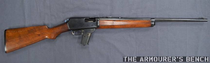
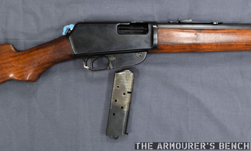
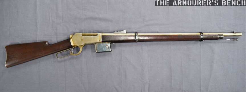
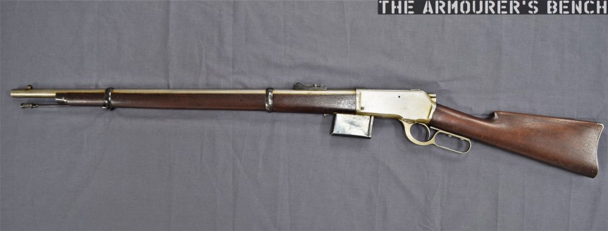
The rifle we’re examining is one of dozens of designs sold by the Brownings to the Winchesters Repeating Arms Company during their long relationship. This design dates from the early 1890s and represents one of Browning’s numerous attempts to move away from the tube magazine-fed designs favoured by Winchester.
The prototype is based around the lever-actuated vertically sliding locking block patented by Browning in May 1884 and first used by Winchester in the Model 1886. The rifle itself is in the ‘military musket’ configuration with full-length handguards, military sights, a cleaning rod and able to mount a bayonet.
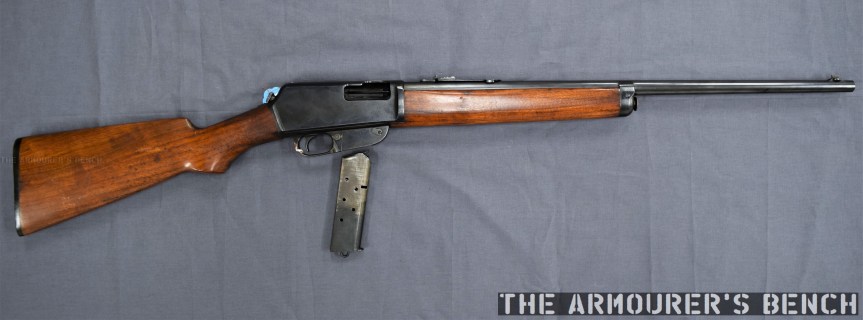
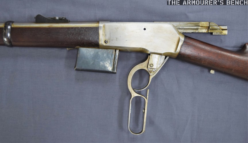
Right side of the rifle (Matthew Moss)
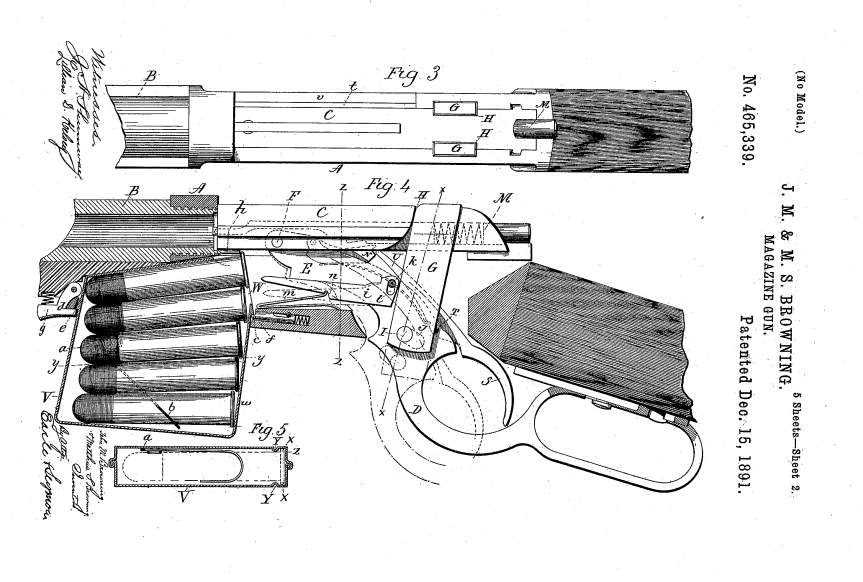
The rifle is chambered in a .45 calibre cartridge, likely .45-70, and weighs just over 9lbs. Browning patented the design of the rifle and magazine in August 1891, with the patent being granted in December (US #465339). It is attributed to John Moses Browning and his younger brother Matthew S. Browning.
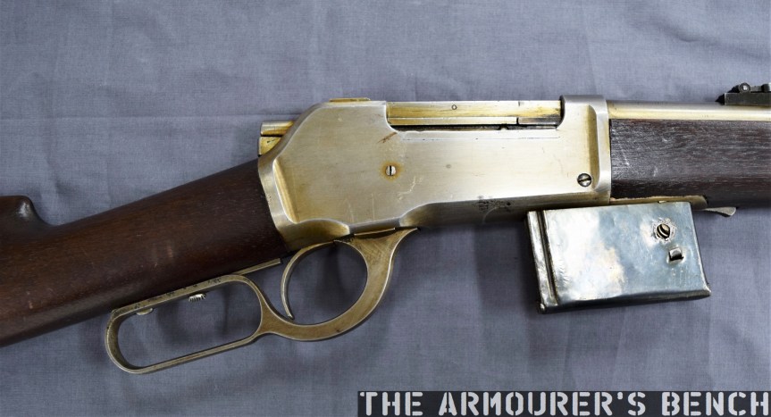
The most interesting feature of the rifle is its detachable box magazine. The magazine is held in place by a spring-loaded catch at the front of the magazine which locks against a tab in the magazine’s wall.
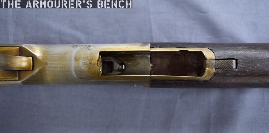
A close up of the magazine well, note the added metal lip of the front of the well, not a part of the receiver (Matthew Moss)
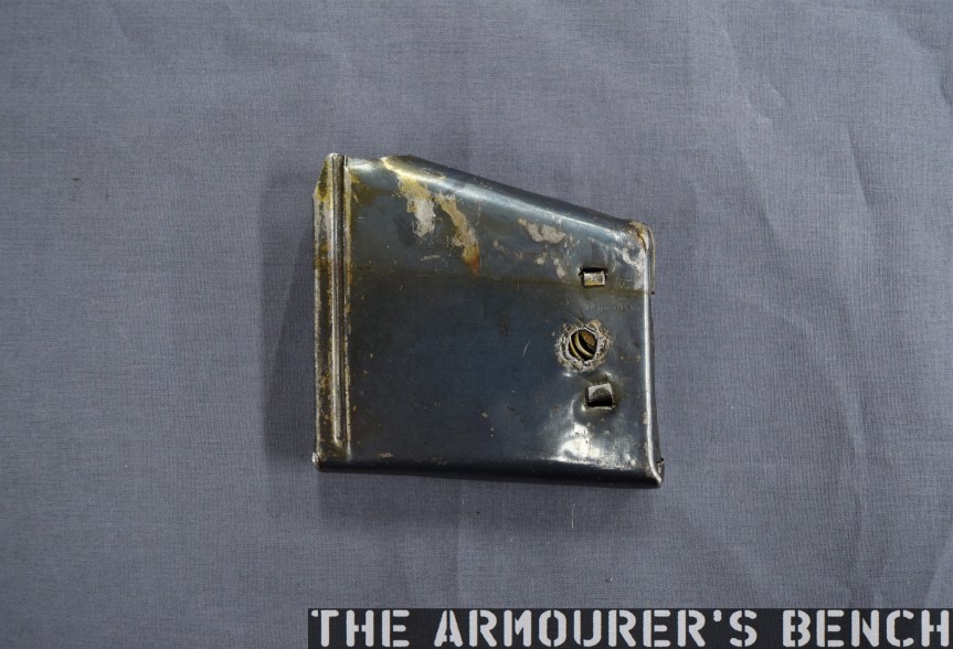
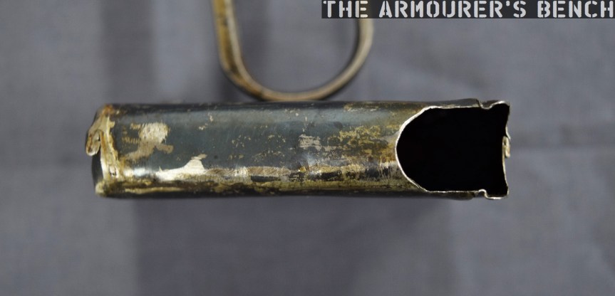
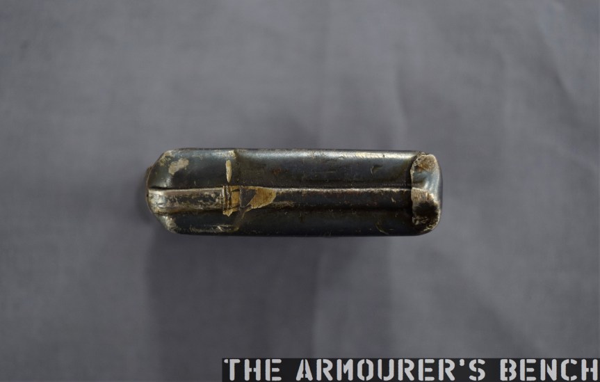
It differs from the box magazines previously developed by James Paris Lee, which Lee begun developing in the mid-1870s (see examples listed below). It’s a simple design with a follower powered by a coil spring. The prototype mag itself is made from pressed metal and is held together with some rough welds. Unlike the magazines we’re familiar with today, the top of the Browning’s magazine is almost entirely enclosed with only a small opening at the rear. The rounds would be loaded nose-first with their rims sliding into the channel at the rear of the magazine.
Close up of the magazine removed from the rifle – right side (Matthew Moss)A view of the top of the magazine with the small opening and notch for the cartridge rime visible (Matthew Moss)
The single-stack magazine appears to hold around five rounds, with Browning’s patent supporting this. The position of the magazine, in front of the action – not below it, is a hint at how it worked. An almost fully enclosed magazine does have its advantages – it would have prevented dirt from entering the mag and it also overcame the need for feed lips which were susceptible to damage, one of the elements which took Lee some time to perfect.
A close up of the front wall of the magazine, note the locking notch (Matthew Moss)
So How Did The Magazine Work?
There is a shoulder on the underside of the bolt which caught the rim of the cartridge which was protruding from the magazine. The bolt pulled the cartridge backwards, out of the magazine and onto a cartridge lifter. As the lever reached its full forward travel the lifter then elevated the round up into line with the breech. When the lever was cycled back again the round was pushed off the lifter and chambered, just as in a normal tube-fed Winchester. As the lever reached the end of its return travel the locking block rose to locked the action.
The Browning’s 1891 patent for the magazine, note ‘h‘ is the shoulder which pulled rounds out of the magazine (US Patent Office)
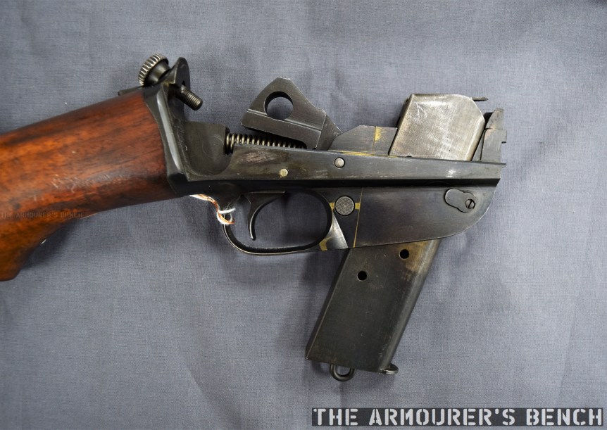
The prototype has a sliding safety bar that locks the lever and blocks the trigger. The trigger differs from the Model 1886 as it is integrated with the lever. In the photograph below we can see the locking block descended, with the lever forward, and the breech block to the rear with the action open. We can also see the striker assembly at the rear of the bolt. The striker cocks on closing when the lever is returned rearward.
The rifle with its action open, bolt o the rear and lever forward. Note the striker assembly at the rear of the bolt (Matthew Moss)
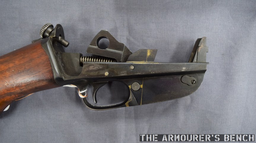
It’s quite an exposed action, with the entire top of the action open. With the action closed in the photograph below we can see the extractor running along the right side of the bolt.
A close up of the rifle’s receiver which is still ‘in the white’ (Matthew Moss)
It’s clear from the design of the magazine that Browning didn’t intend the rifle to be reloaded with stripper clips, although single loading of the rifle itself (not the magazine) would have been possible. When compared to other contemporary system this would have been somewhat of a disadvantage compared to Lee’s magazine’s later loading with chargers and stripper clips. However, from examination of Browning’s 1891 patent his intention becomes clear, the patent explains that he intended for the magazine itself to be replaced:
“One magazine may be readily removed from the gun and another introduced in its place, so that the person, using the arm may have at hand several magazines to be interchanged as the cartridges from one magazine are exhausted.”
This is a concept that wouldn’t be accepted by militaries for decades. Winchester purchased the rights to the design but this was one of many designs Browning sold the company which never saw production. The design and prototype are fascinating and represent one of Browning’s lesser-known concepts.
Left side profile of the rifle (Matthew Moss)
This rifle is a unique prototype and it was a true honour to examine it. It’s now on display at the newly refurbished Cody Firearms Museum, at the Buffalo Bill Centre of the West. The new museum is phenomenal and well worth a visit. Our thanks to the museum for allowing us to film items, like this one, from the museum’s collection.
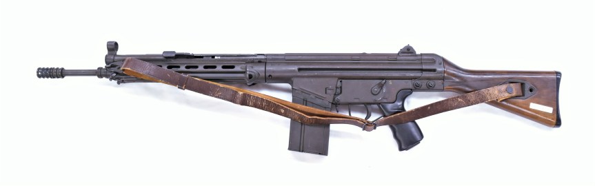
We’re all familiar with the Heckler & Koch G3 and its roller-delayed blowback action. What is less well-known is that H&K were one of two companies originally contracted by the West German government to produce the Bundeswehr’s new service rifle. The other company was Rheinmetall and today we’re lucky enough to be taking a look at an example of an early production Rheinmetall G3.
Left side (courtesy of the Cody Firearms Museum)
The rifle which became the G3 was of course originally developed by German and Spanish engineers working at the Centro de Estudios Tecnicos de Materiales Especiales (CETME) and was intended to equip the Spanish armed forces. Initially, the West German Bundesgrenzschutz (border guards) were interested in purchasing a substantial number of the new CETME rifles, with an initial order for 5,000 agreed, however, in September 1955 the order was cancelled due to delays in production and the Bundesgrenzschutz subsequently ordered the FN FAL instead.
In November 1955, the Bundeswehr (West German military) was formed and began to search for a suitable new 7.62x51mm service rifle. Having observed the Bundesgrenzschutz’ testing the fledgling Bundeswehr took an interest in the CETEME rifle. 400 ‘STG CETME’ rifles were ordered for troop trials and these were assembled in Germany by Heckler & Koch. The rifles were delivered in late 1956, and comparative trials against the FAL began the following year.
CETME Model A (Courtesy of P. Hokana)
The trials found the ‘STG CETME’ to be satisfactory in terms of features and design but lacking in durability. A number of small changes were requested including a flash hider suitable for launching rifle grenades, either a flip-up or dioptre rear sight instead of a traditional tangent style, a case deflector, a simpler more ergonomic pistol grip, a longer more ergonomic cocking handle, changes to the recoil spring guide and tweaks to the shape of the buttstock. Additional improvements such as a stronger bipod, lighter magazine, a last round hold open mechanism, overall lightening of the rifle, a lighter 20-round magazine and a proper handguard were also requested.
Left-side of the G3’s receiver, note the partial reinforcing rib on the magazine housing (Matthew Moss)
FN were unwilling to grant Germany a manufacturing license and the $110 per rifle price for the FAL proved substantially higher than CETME’s production estimates (The ArmaLite AR-10, J. Putnam Evans (2016), p.204). With adoption looking likely, legal wrangling over patent ownership began between Mauser, Rheinmetall and Heckler & Koch. All claimed the ownership of the roller-delayed blowback principle used by the CETME rifle. Eventually, however, the West German government awarded Rheinmetall and H&K future production contracts for the new rifle with the government supporting H&K’s claims but the legal battles continued for almost a decade.
In the meantime, with production of the CETME rifle not yet initiated and in light of some durability/reliability issues suffered during the STG CETME’s troop trials, 100,000 ‘Series C’ FN FALs were ordered for the Bundeswehr in late 1956. In 1957 the Swiss SIG 510 (designated the G2) and the American ArmaLite AR-10 (designated the G4) were also evaluated. Once the modifications requested after the troops trials were completed by H&K, a run of twenty rifles was produced and tested again.
A view inside the ejection port of the G3 with the charging handle locked back (Matthew Moss)
In 1959, the West German government finally adopted the CETME rifle, designating it the G3. The German federal government decided that they wished to purchase the worldwide manufacturing rights to the G3, which naturally the Spanish government was reluctant to agree to. An agreement was finally reached in January 1958 and the contract giving West Germany worldwide rights to the G3 was finalised on February 4th, 1959.
One issue was that in June 1957, CETME had agreed a licensing deal for manufacture and sale of the rifle with a with a Dutch company Nederlandsche Wapen en Munitiefabriek (NWM). In order to gain the manufacturing rights sold to NWM the German government awarded the Dutch company a lucrative contract producing 20mm ammunition (Full Circle, p.234).
A close up of the trigger mechanism housing, note ‘Germany’ faintly scratched into the surface (Matthew Moss)
Interestingly, as the German government owned the manufacturing rights, H&K initially had to pay the government 4 Deutsche Marks per rifle, despite having been awarded the contract by the German government. In late January 1959, H&K were awarded the first substantial production contract, amounting to 150,000 rifles. Rheinmetall were subsequently awarded a similar contract (Full Circle, p.235).
According to R. Blake Stevens’ book on the roller-delayed blowback action, Full Circle, Rheinmetall produced 500,000 G3s during the 1960s, delivering 8,000 rifles per month (Full Circle, p.287). As H&K had been designated as the technical lead on the G3 project, Rheinmetall’s engineers made no attempts to develop modifications or improvements and even when H&K had switched to plastic furniture the Rheinmetall guns continued to use wood. Rheinmetall’s only other G3-related project was the RH4, a 7.62x39mm chambered, roller-locked but gas-operated rifle designed for export (Historical Firearms).
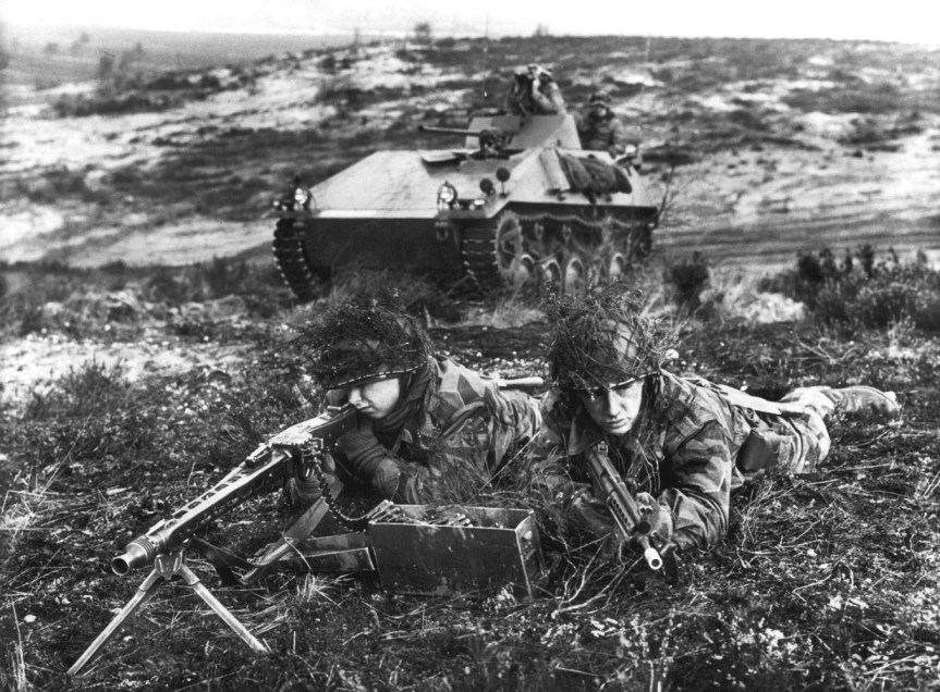
W. German Army Armoured Reconnaissance car, with MG3 team with No.2 armed with G3, c.1960 (US Army)
In addition to the G3, Rheinmetall were the sole manufacturer of the MG3 machine gun, the 7.62x51mm MG42. Blake Stevens explains that in 1969, when a new tender for MG3 production was due, that H&K moved to undercut Rheinmetall who had until now held the monopoly on MG3 production (Full Circle, p.292). As a result an agreement was reached where Rheinmetall retained their monopoly on MG3 production and H&K became sole manufacturer of the G3 for the West German military.
Examining An Early Production Rheinmetall G3
The G3 went through a large number of changes both before and after it went into service. The rifle we’re examining today is a good example of an early production rifle, as adopted in 1959. This rifle is lightly marked with ‘G3 [Rheinmetall’s ‘star-in-a-circle’ logo] followed by a serial number of 745 and below that it is date marked with the ‘3/60’, for March 1960.
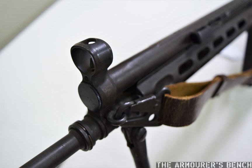
A close up of the G3’s front sight and sling attachment point (Matthew Moss)
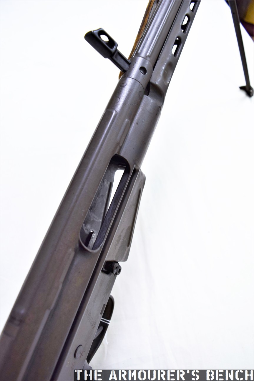
Working our way from the muzzle back; the rifle has the early style of flash-hider/grenade launcher support which was introduced in 1957 and altered in early 1961, an enclosed front sight and a detachable bipod (which was not Bundeswehr general issue). It has a stamped metal handguard which was replaced by one with a wooden insert in 1961, before H&K introduced plastic furniture in 1964.
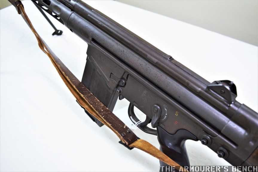
The G3 field stripped (Matthew Moss)
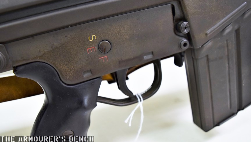
The folding carrying handle seen on the troop trials rifles has been removed, the receiver is stepped for the attachment of a scope base and the magazine housing has a single strengthening rib, rather than the later ‘full-frame’ continuous rib. It has an S-E-F selector (S – Sicher/safe, E – Einzelfeuer/semi, F – Feuerstoß/auto) and black plastic pistol grip. Internally, the rifle has a captive mainspring. Unlike later G3’s the rifle has a 2-position folding L-shape rear aperture sight with apertures for 200 & 300 metres rather than the later dioptre sight adopted officially in mid-1960. The rifle has a wooden stock held with a stamped metal sling attachment and a plastic buttplate.
In addition for the full episode on the Winchester Experimental Submachine Gun, we have also put together a video showing the reassembly process for the N2 prototype that we disassembled and examined in the main video. Check it out below:
My thanks to the Cody Firearms Museum at the Buffalo Bill Center of the West for allowing me to examine and film the Winchester submachine gun prototypes. Special thanks to the CFM’s assistant curator Danny Michael for helping disassemble and reassemble the N2.
If you enjoyed the video and this article please consider supporting our work here.
Held in the collection of the Cody Firearms Museum (CFM), at the Buffalo Bill Centre of the West, is a most intriguing Cold War submachine gun. The weapon came from the collection of the old Winchester Firearms Museum, which the CFM inherited, it is not a test & evaluation weapon made by another company but a submachine gun designed and developed by Winchester. Those who know their Winchester history will know the company had no prior background in submachine gun design, instead being best known for their rifles and shotguns.
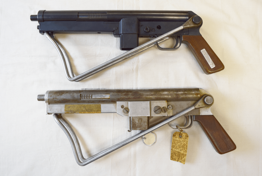
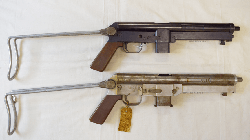
Left side profile view of the N4 and N2 Winchester submachine gun prototypes with their stocks folded (Matthew Moss)
Very little is known about Winchester’s submachine gun project, but two prototype examples survive, an early ‘in the white’ model labelled ‘N2’ and another which Herbert Houze, the CFM’s former curator, designated ‘N4’ . The documentary evidence for the Winchester submachine guns is sparse, amounting to just entries in the Winchester Museum’s inventory and a faded battered item tag attached to N2. A confusing element is that the inventory simply refers to the two prototypes as N-1 and N-2, with no mention of an N4.
There is also believed to be original engineering drawings housed in the Winchester Archival collection, currently held by the McCracken Research Library, but searches by myself and library staff have been unable to locate these.
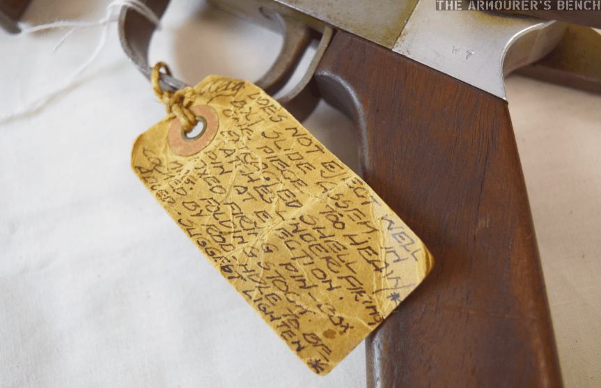
It is unclear if the tag from N2 is contemporary, perhaps added when the gun was handed over to Winchester’s museum, or if it was added later. In under 100 words it give us a short potted history of the N2 itself and the company’s programme to develop a submachine gun.
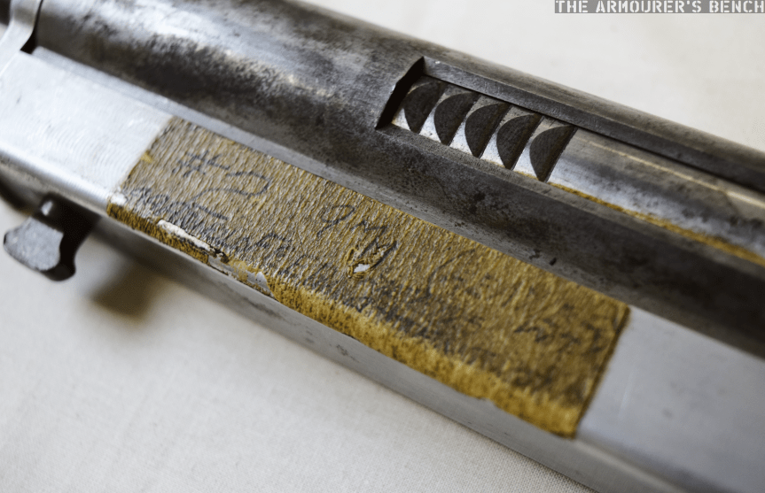
Close up of the N2’s item tag detailing the gun & program’s history (Matthew Moss)
Houze suggests the development programme began in 1955 and the tag attached the N2 suggests that development ceased in 1957, whether this is solely for that gun or the entire programme is unclear. This would make Winchester’s weapon a contemporary of the famous Israeli UZI.
The tag describes the N2 as a 9mm blowback ‘NATO Burp Gun’, followed by the name A.A. Arnold, a Winchester engineer perhaps best known for writing a series of manuals for Winchester firearms, followed by ‘dropped Dec ’57’. In his 1994 book, Winchester Repeating Arms Company: Its History & Development from 1865 to 1981, Houze suggests that the weapons were designed by A.A. Arnold and Melvin M. Johnson in 1955, for possible adoption by NATO. The association with NATO might also be the origins of the ‘N’ prefix. I have been unable to find any published patents attributed to Arnold, Johnson or the company relating to the experimental submachine gun.
I contacted NATO’s Archives who advised that they were unable to find any reference or documentation relating to a direct NATO submachine gun requirement. Another possibility is that the weapon was developed to market more broadly to NATO member nations. The submachine gun market at this time in Europe, however, was already saturated by both wartime surplus and a new generation of guns, including the Sterling, the UZI, the Madsen M50, and the Carl Gustav m/45.
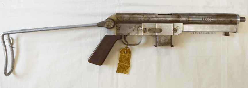
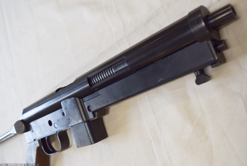
Right side profile view of the N2 ‘in-the-white’ prototype with its stock deployed (Matthew Moss)
The reverse of the N2’s label documents the prototype weapon’s reliability and feeding problems. The tag states that the N2 did “not eject well” and that the bolt slide assembly was too heavy. It also highlights failures to cycle properly with extracted cartridge cases catching under the firing pin. The label then gives a brief description of some of the N2’s features: “fixed firing pin, 33x Mag. Folding stock.” Interestingly, it also notes that the weapon would be cocked by a rod – the hole for which had not yet been added. The tag ends with a suggestion that the heavy one piece bolt assembly should be lightened.
Close up of the N2’s difficult to decipher tape note (Matthew Moss)
N2 itself also has a piece of masking tape, on the recoil spring assembly cover, with its serial number and calibre written on it, along with A.A. Arnold’s name and some words that are too difficult to make out, but include ‘feed’.
Houze has also suggested that Melvin Johnson, designer of the Johnson rifle and light machine gun who joined Winchester as a designer and adviser in the early 1950s for a short time, and Stefan Janson, designer of the Brtish E.M.2 bullpup and subsequent Winchester engineer, both worked on the project. However, I have been unable to find any documentary evidence of their involvement.
Examining the N2:
Winchester N4 and disassembled N2 prototype (Matthew Moss)
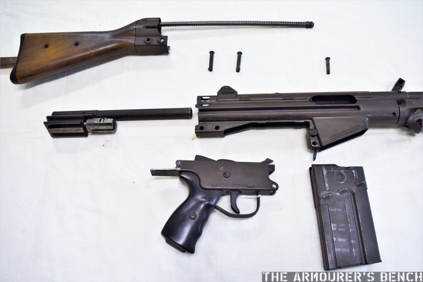
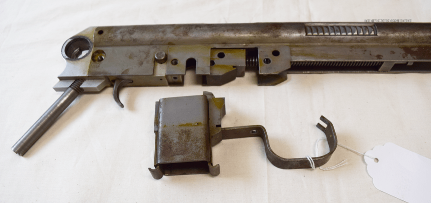
We can learn a lot from hands on examination of the two Winchester ‘N’ prototypes. Examining N2 we find that the receiver is made up of a piece of shaped sheet metal with a rounded upper half containing the barrel, bolt and cutouts for the grip points on the bolt assembly that allow charging. The bolt assembly rides over the rear portion of the barrel and projects back into the receiver. The lower section of the stamped receiver is rectangular and has a cut out for a separate magazine housing and fire control mechanism consisting of a trigger and push through safety – which we did not remove during disassembly. The N4 is missing its safety.
Close up of the N2’s magazine housing and trigger guard, note also the trunion freed from the receiver (Matthew Moss)
In the N2, the magazine housing is held in place by the stamped metal trigger guard which rocks into a notch behind the trigger and at the front interfaces with a notch in the magazine housing which has to be placed in the receiver at the same time, both are then held in place by a screw. This was changed in the later ‘N4’ with the trigger guard as a separate independent piece.
Winchester N2 Prototype Reassembly:
The side plates, muzzle end cap and recoil spring assembly cover all made from Aluminium – ostensibly to reduce weight. The submachine gun prototypes both use a pinch cocking method similar to that seen in the earlier British BSA WELGUN developed during WWII. The recoil spring proved to be too strong to cock easily, the addition of ‘rod’ cocking handle is suggested on the N2’s tag. The blued, later N4 prototype, however, is still lacking a conventional cocking handle. The pinch cocking method is not ergonomic, the user’s fingers could easily be caught by reciprocating bolt in charging cut outs in the receiver.
The N2 prototype disassembled, sadly we were unable to free the bolt from the receiver (Matthew Moss)
Another ergonomic consideration is the Winchester’s submachine gun’s unusually swept back pistol grip angle, the angle of the forward grip made by stock when folded is also similarly angled. Both the weapons have a push though safety selector just above the trigger (likely safe & fully automatic, but could not check as gun unable/difficult to cycle the prototypes easily). The weapon likely fed from a double stack, single feed magazine – either of an similar pattern to the MP40 or proprietary. The N4 seen in Houze’s 1994 book is shown with an MP40 magazine. UZI magazines fit the weapon but don’t lock into place.
The basic design does not change substantially between the prototypes with the control configuration, folding wire stock, pistol grip angle and magazine housing dimensions remaining the same. The N4, however, differs from the earlier prototype in a number of respects. The N4’s nose cap now fits over the rounded half of the receiver, rather than sitting flush and the cut outs in the upper receiver to access the bolt assembly for charging have been moved back slightly.
Right side view of the N4 blued prototype, note the half cocked bolt and the narrower grip serrations on the bolt assembly. Note also the intersection points of the recoil spring assembly cover and the upper receiver (Matthew Moss)
The later N4 model has pins in place of some of the screws used on the N2. The side plates have been replaced by a one-piece recoil spring assembly cover which projects back further over the magazine housing to the rear of the receiver. The most fundamental difference between the two is that it appears that the front part of the N4’s receiver has been significantly altered with the lower receiver at the front of the gun removed. It appears to have been replaced by the recoil spring assembly cover which appears to slot into the receiver. Sadly, we didn’t have time to disassemble the N4 to examine this.
The N4’s bolt assembly also has more serrations, in a slightly different orientation, on its bolt assembly gripping area, but still no charging handle as recommended on the N2’s tag. The ejection port on the blued prototype is also at a position closer to 12 o’clock when compared to the N2s.
Right side profile view of the two prototypes with their stocks deployed (Matthew Moss)
The N2 has a metal trunnion block, that the recoil spring guide rod screws into, this is held in place within the receiver by a cross pin. The bolt appears to be removed through the rear of the receiver once the stock assmbly/end cap is removed and the bolt assembly freed.
The folding stock was retained by spring tension of the wire metal stock against a wingnut-shaped catch that is riveted onto the recoil spring assembly cover. The stock is locked by a spring loaded push button system similar to the MP40s, this is not particularly sturdy. The shape of the wire stock itself is reminiscent of the US M3. When folded the butt of the wire stock acts as a front grip, the retention of the stock is surprisingly strong and stable.
Intriguingly, the Winchester Museum inventory notes that the guns are designated the N-1 and N-2, with an additional wooden model of the ‘Nato Burp Gun’ being transferred along with a box of duplicate parts in steel for the N2’s aluminium parts.
If you enjoyed the videos and this article please consider supporting our work here.
Winchester Repeating Arms Company: Its History & Development from 1865 to 1981, H. Houze (1994)
My thanks to the Cody Firearms Museum at the Buffalo Bill Center of the West for allowing me to examine and film the Winchester submachine gun prototypes. Special thanks to the CFM’s assistant curator Danny Michael for helping disassemble the N2.
All photographs taken by Matthew Moss, courtesy of the CFM & the Buffalo Bill Center of the West. Please do not reproduce photographs without permission or credit.
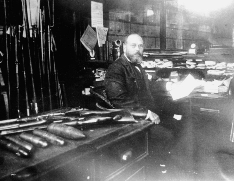
Today we’re examining an intriguing firearm with a fascinating history. It is difficult to understate the potential importance of the Curtis Rifle. Despite being designed in Britain in the 1860s the firearm gained more notoriety when it was offered as evidence in a legal battle between the Winchester Repeating Arms company and Francis Bannerman. What makes the firearm most noteworthy, however, is its fundamentally unconventional layout. Designed by William Joseph Curtis in the mid-1860s, it is arguably one of the earliest ‘bullpups’ and almost certainly the first repeating bullpup.
William Curtis’ 1866 ‘bullpup’ rifle, built in 1895 by Winchester (Photo by Matthew Moss, courtesy of the Cody Firearms Museum)
For the purpose of this article it would be wise to first define what a bullpup actually is. It can be defined as a weapon with a somewhat unconventional layout which places the action and magazine behind the weapon’s trigger group. This has the benefit of maintaining a conventional rifle’s barrel length while making the overall length of the rifle more compact.
Bullpup rifles became popular with a number of militaries around the world during the 1970s and 1980s – namely the Austrian Steyr AUG, the French FAMAS and the British SA80, and more recently with rifles from China and Singapore as well as the Tavor series of rifles from Israel.
Thorneycroft, Farquhar and Hill’s 1905 carbine patent (source)
The bullpup, however, dates back much further with some argument to be made for the first firearms to utilise the concept being 19th century percussion target shooting rifles. The earliest military bullpups date to the beginning of the 20thth century, these include a rifles designed by Samuel McClean, the initial designer of the Lewis Gun, patented in 1896 (US #723706), by Major Philip Godsal (US #808282) and a carbine developed by James Baird Thorneycroft in 1901. Thorneycroft subsequently worked with Moubray Gore Farquhar and Arthur Henry Hill to patent a refined version of the carbine in 1905 (US #827893). While the Thorneycroft was tested by the British army it was rejected due to ergonomic and reliability shortcomings.
In 1908 Lieutenant-Colonel Armand-Frédéric Faucon of the Troupes Coloniales (French Colonial Infantry) began developing what he termed a ‘Fusil Équilibré’ or balanced rifle. Faucon patented his concept in France in 1911 (FR #422154) and continued to work on the balanced rifle during World War One, utilising a Meunier A5 semi-automatic rifle in working prototypes. The Faucon-Meunier rifle was tested in 1918 and 1920 but eventually rejected. It would be nearly 45 yeas before the bullpup concept was revisited by a major power. Engineers working at the Royal Small Arms Factory at Enfield and at the British Armament Design Department in the 1940s began to develop designs based around the bullpup concept. (Some of these will hopefully be the focus of future videos!)
William Curtis’ design, however, predates all of these. Patented in Britain on 10th July, 1866, Curtis is listed by the London Gazette as a Civil Engineer. His design is unlike anything that had been seen before. Based on a slide-action with a drum magazine, it was placed over the shoulder – much like a modern shoulder-fired anti-tank weapon.
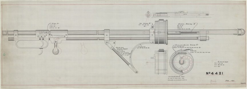
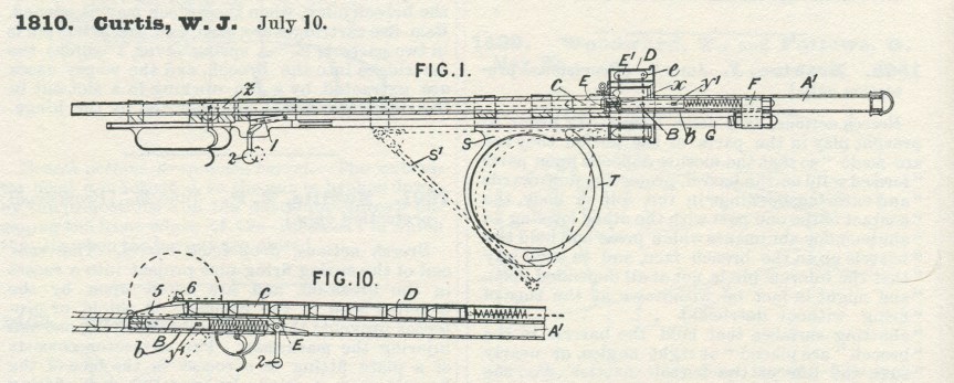
William Joseph Curtis’ July 1866 patent for ‘Breech actions, sliding breech-block & stocks’ (courtesy of Research Press)
Curtis’ rifle is probably the very first bullpup magazine rifle, one of the earliest to have a drum magazine (an Italian, Marco Antonio Francois Mennons, patented an earlier design for a drum magazine in March 1862, GB #637) and also an early striker-fired design. Clearly a design well ahead of its time and radically unconventional.
This unconventional gun’s designer was born in Islington, London in 1802, as a civil engineer he worked on Britain’s rapidly growing railway network. He died in 1875, placing the development of his rifle nearer the end of his life. With hindsight Curtis’ design clearly had revolutionary potential but it appears that his concept was never taken up. It appears that he only patented his design in the United Kingdom. If not for a corporate lawsuit on another continent, decades later, then it is possible Curtis’ design, like so many others, would have slipped into historical obscurity.
Francis Bannerman vs. the Winchester Repeating Arms Company
In 1890, Francis Bannerman VI, a successful entrepreneur specialising in junk, scrap and later surplus, purchased the Spencer Arms Company and the rights to their patents. The company had been founded by Christopher Miner Spencer, designer of the Spencer Rifle, they produced the first commercially successful slide or pump-action shotgun. This pump action shotgun was designed by Spencer and Sylvester H. Roper and patented in April, 1882 (US #255894). Bannerman continued producing the shotgun as the Bannerman Model 1890, however, in 1893 the Winchester Repeating Arms Company, introduced the John Browning-designed Model 1893 pump shotgun (US #441,390).
Spencer & Roper’s 1882 patent for their pump action shotgun (source)
In response in October 1894, Bannerman filed a law suit against the Winchester Repeating Arms Company claiming that the slide/pump actions used by Winchester’s Model 1890 and new Model 1893 shotgun infringed on the patents that he owned.
He called for the court to force Winchester to halt production and claimed $10,000 in damages and royalties for the sale of guns which he believed infringed his patent. Winchester temporarily halted production of the Model 1893, in the meantime Bannerman continued producing and improving his shotgun introducing the 1894 and 1896 models.
News report on the ruling of the Bannerman vs Winchester case from The Times (Philadelphia), 27th June, 1897
Various contemporary newspaper reports suggest between 100,000 and 500,000 people were directly interested in the case as ordinary owners were liable under the conditions of Bannerman’s suit.
Winchester dispatched George D. Seymour to Europe to scour the French and British patent archives for any patents for similar actions that had been filed there before those now owned by Bannerman. Winchester discovered four patents: three British and one French. The earliest of these was Alexander Bain’s patent of 1854. Two more patents held by Joseph Curtis and William Krutzsch were found, dating from 1866. The later French patent was filed by M.M. Magot in 1880. All of these designs, including the Curtis we are examining here, never progressed beyond the development stage and were largely forgotten until rediscovered by Winchester.
Model of William Krutzsch’s pump action rifle (Photo by Nathaniel F, courtesy of Cody Firearms Museum)
Winchester claimed that these earlier designs invalidated Bannerman’s patent claims. To illustrate their defence Winchester decided to build working models of each of the designs, breathing life into long forgotten patent drawings. This must have been a major engineering task as the patent designs would not have had all the information needed to produce a working model.
In 1895-96 Winchester engineers, including T.C. Johnson, assembled working models of each of the designs to prove their viability. These were tested and Winchester’s lawyers took them into court and submitted them as evidence, even offering a firing demonstration. The court declined the demonstration and made its decision on June 27th 1897. Judge Hoyt H. Wheeler of the United States District Court for the Southern District of New York ruled in favour of Winchester and threw out Bannerman’s suit.
Winchester had produced some 34,000 Model 1893s before, in November 1897, they introduced the improved Model 1897 which proved to be hugely popular on both the civilian and military markets. Bannerman unveiled a final shotgun, the Model 1900, but production ended in the early 1900s.
Curtis’ Unconventional Design
Right side, rear quarter, view of the Winchester-made Curtis Rifle (Photo by Matthew Moss, courtesy of the Cody Firearms Museum)
Curtis’ design encapsulates a number of features which, in 1866, were unheard of and arguably revolutionary. Not only is it probably the first magazine-fed repeating bullpup but it also uses a drum magazine, something that would not see substantial military use until the First World War. It has a folding shoulder support or stock, uses a striker fired action and makes use of self-contained ammunition.
This slideshow requires JavaScript.
The Curtis’ rifle is placed over the top of the user’s shoulder with a folding leather strap which fits into the shoulder pocket. Curtis’ original patent also suggests a fixed hook and strap. The user then grasps the loop near the muzzle with their support hand and the trigger and bolt handle with their other hand. Novel, but not the most ergonomic of designs.
Illustration of how the Curtis Rifle was ‘shouldered’ (Courtesy of the Cody Firearms Museum)
The magazine appears to hold at least 13 or more rounds according to the available patent and Winchester’s engineering drawings. The magazine is fixed in place and rounds appear to have been fed into it through the loading/ejection port on the left side of the weapon. This would have also put spent cases being ejected right next to the user’s neck. Curtis’ patent explains that the magazine has a spring inside which has a length of string attached to the top of it which the user can pull back to depress it and allow cartridges to be loaded into the drum. The magazine has a single stack or loop of cartridges. Once loaded the string can be released, allowing the magazine spring to push rounds into the action.
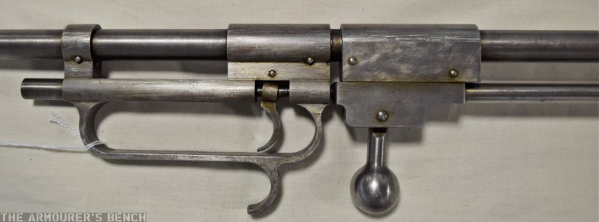
Close up of the left side of the Curtis’ trigger, bolt assembly and hand loop (Photo by Matthew Moss, courtesy of the Cody Firearms Museum)
The Curtis rifle’s action appears to lock at the front of the weapon with the bolt handle acting on a hinged, spring-loaded, locking piece or flapper which dropped into place when locked. To unlock the action the bolt handle was sharply pulled to the rear which pushed the locking piece out of engagement and unlocked the action allowing the operating rod to be cycled.
The weapon’s chamber appears to be just forward of the centre of the drum magazine with the striker assembly located behind it. To operate Curtis’ rifle the magazine was loaded and then the user had to unlock the action by pulling the bolt handle backwards. This then allowed the operating rod to be pulled backwards, like a pump action, which pushed the bolt and striker assembly to the rear, cocking the striker, the bolt handle was then returned forward and locked back into position. This chambered a round ready to be fired.
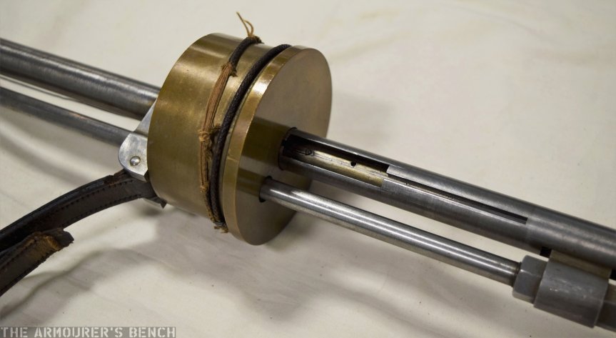
Close up of the Curtis’ brass drum magazine and loading/ejection port (Photo by Matthew Moss, courtesy of the Cody Firearms Museum)
The trigger at the front of the firearm is connected to the striker assembly by a long length of wire. When pulled the wire becomes taught and trips a sear to release the striker, firing the weapon.
Originally Curtis’ patent describes how ‘small punches’ on the bolt face would pierce the cartridge base during firing to enable the spent case to be extracted once the action was cycled. From Winchester’s engineering drawings, however, it appears they replaced this with a more reliable and conventional extractor at the 7 o’clock position of the bolt face.
Given that the weapon would have fired black powder cartridges it is unclear how well the rifle would have faired with sustained firing. The drum magazine would have been susceptible to jamming as a result of powder fouling. This, however, would not have been an issue for Winchester later version of the rifle.
Detail of Fig.1 & Fig.10 from Curtis’ 1866 patent (courtesy of Research Press)
But the Curtis has one more interesting surprise. The original 1866 patent also includes what might be one of the earliest descriptions of a gas operated firearm. One of the most fascinating sections of Curtis’ original patent details how the rifle might have been adapted for gas operation:
“An arrangement is shown in Fig.10, in which the rod G is dispensed with; in this case the barrel may be shorter, not projecting beyond the shoulder; the butt is similar. The breech may be opened automatically by the powder gases, which pass by an opening in the barrel to a cylinder with which works a breech operating plunger.”
Curtis does not go into further detail but he is clearly describing a piston-driven, gas operated system. The patent drawing also depicts an alternative tube magazine instead of the drum magazine.
It is unknown if Curtis ever put his theory to the test and developed his gas system idea further. It is tempting to wonder if, in 1895 when Winchester were assembling their model of the Curtis, if John Browning or William Mason, who were also developing their own gas operated systems at the time, were aware of Curtis’ idea from 30 years earlier. As such Curtis’, admittedly vague, gas system pre-dates the first patents on gas operation by just under 20 years.
If you enjoyed the video and this article please consider supporting our work here.
Specifications:
Action: Slide action
Calibre: .32 Winchester Centre Fire
Feed: ~12 round drum magazine
My thanks to the Cody Firearms Museum at the Buffalo Bill Center of the West for allowing me to examine and film the Curtis. Special thanks to the CFM’s assistant curator Danny Michael for making extra time to open up the case where the rifle Curtis is on display so we could examine it and for also sharing Winchester’s technical drawings and other records.
Thanks also to David Minshall of Research Press.co.uk for his assistance finding Curtis’ original British patent abridgement and to John Walter for digging up some additional information about Curtis’ life.
Bibliography:
‘Winchester Suit Decided’, The Times (Philadelphia), 27th June, 1897
‘Recollections of the Forming of the Pugsley & Winchester Gun Collections: A Talk Given by Mr. Edwin Pugsley at the New Haven Meeting of the AS of AC’, September, 1955.
My thanks to the Cody Firearms Museum, at the Buffalo Bill Centre of the West, for allowing me to film the revolver. I am very lucky to have handled it as it is normally on display.
The US Patent Office granted Samuel Colt a patent for his ‘Revolving Gun’ in February 1836 (US #9430X). Colt had already patented his design in Britain in October 1835 – at the age of just 21. He subsequently patented his design across Europe and worked with Baltimore gunsmith John Pearson to build a number of prototype revolvers. Colt’s pistol was not the first revolver but it did embody a number of important features combining the use of percussion caps and a bored-out cylinder with a single action trigger mechanism and cylinder locking bar.
With backing from his cousin and other investors Colt established the Patent Arms Company, building afactory in Paterson, New Jersey in late 1836. The Patent Arms Company produced a variety of revolvers in different sizes including pocket, belt and holster models. The .28 calibre Pocket Model No.1 being the smallest and the .36 calibre No.5 holster revolver being the largest. The company produced approximately 2,300 – 2,800 firearms (sources have various estimates on just how many revolvers and revolving rifles were manufactured) before the company collapsed, due to insufficient sales, in 1842.
The Colt Paterson
It was the No.5 which saw the greatest sales with small numbers being purchased by the Texas Rangers, Texan Navy and private citizens. The US Army reportedly tested Colt’s revolver in February and June 1837, finding a number of weaknesses to the design. Despite the approval of President Andrew Jackson the US military remained largely uninterested in the Paterson.
Small numbers of the revolvers were purchased by the U.S. government including 100 for the Navy in 1841 and 50 for the Army in 1845 after the company had collapsed. The Republic of Texas also purchased 180 revolvers for its navy in 1839.
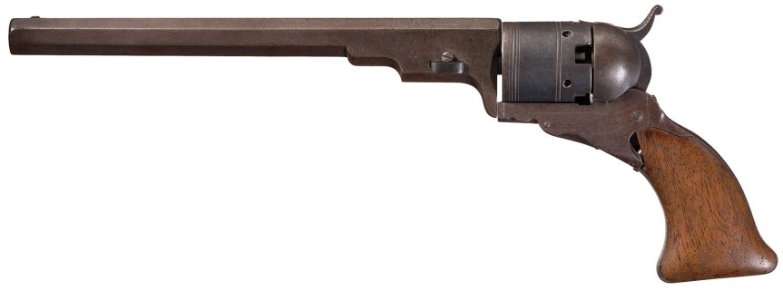
The Paterson has a number of interesting features and lacks some components that would become standard on Colt’s later revolvers. The Patersons had octagonal barrels and were sold in a number of barrel lengths ranging from 2.5 to 9 inches, with 7.5 and 9 inches being the most popular. The barrel assembly attached to the receiver via the cylinder axis pin which was locked together by a wedge – a method which would be used in Colt pistols for over 30 years. They had a small front sight and a notch cut into the hammer that acted as a rear sight. The pistols had no trigger guard, instead they had a folding trigger, which deployed when the weapon was fully cocked. Initially, the Patersons lacked a loading lever beneath the barrel. Instead the cylinder was removed to enable loading and capping with a separate loading tool. Another characteristic of the belt and holster Patersons was their flared pistol grips.
Despite this Colt’s .36 calibre No.5 revolvers proved popular with Texas Rangers, so much so that workers often referred to it as ‘The Texas Arm’, who were frequently engaged in skirmishes with Mexicans and Native Americans. During one engagement with a large Comanche warriors along the Guadeloupe River one ranger recalled: “They were two hundred in number, and fought well and bravely, but our revolvers as fatal as they were astonishing, put them speedily to flight.”
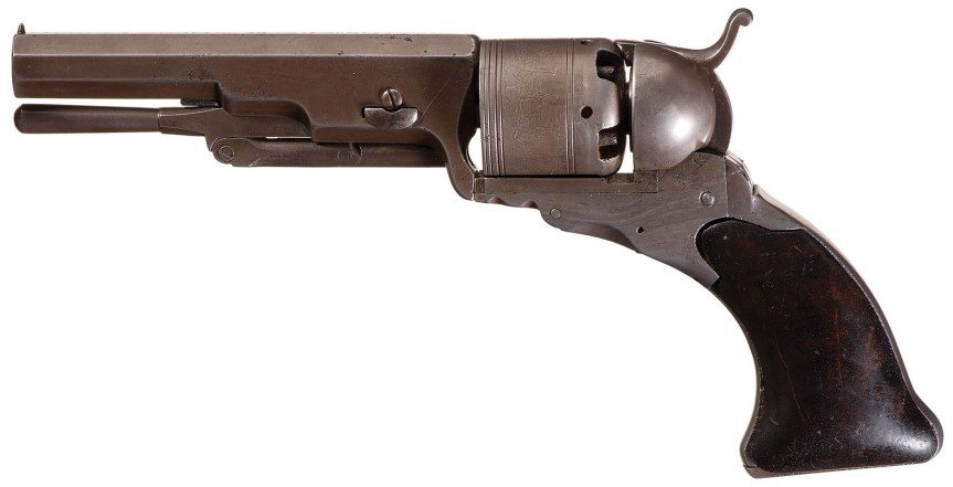
Patent Arms Company ‘Colt Paterson’ No.5 holster revolver (Rock Island Auctions)
Despite the Patterson’s relatively small calibre, lack of an integral loading arm and the frailties of the design (such as a bent axis pin) the revolver’s five round cylinder offered the men wielding them five times the firepower of their muzzle-loading, single shot pistols.
Despite the limited success of Colt’s revolver the design still needed improvements and Colt became determined that the path to success was through military contracts. Sadly, for Colt there weren’t forthcoming and the Patent Arms Company collapsed in 1841/2.
It was the Mexican–American War (1846-48) that revived Colt’s fortunes. Captain Samuel Walker, of the Texas Rangers and the US Army’s Regiment of Mounted Riflemen, was an admirer of Colt’s revolver having carried them in the field for a number of years. So much so that he wrote to Colt in 1846 saying:
“The pistols which you made… have been in use by the Rangers for three years, and I can say with confidence that it is the only good improvement I have seen. …Without your pistols we would not have had the confidence to have undertaken such daring adventures.”
Subsequently, the US government contracted Colt to produce 1,000 large calibre revolvers, the Model 1847. These huge, robust pistols had a fixed trigger and a loading lever as standard.
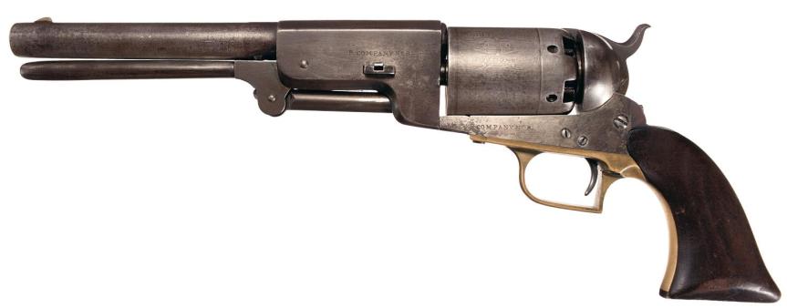
Colt’s Patent Manufacturing Company Model 1847 ‘Colt Walker’ Army Revolver (Rock Island Auctions)
In 1847 Colt began manufacturing what has since become known as the ‘Colt Walker’, a large, .44 calibre revolver with a six-shot cylinder, that weighed 4lbs 9oz (2.07kg). He subcontracted the production to Eli Whitney Jr. who set up tooling to manufacture the new pistols. These were issued to the US Army’s mounted regiments including the Texas Mounted Volunteers, the US Mounted Riflemen and Dragoons. The success of the Colt Model 1847 Army Revolver paved the way for Colt’s future success.
Adapted Colt Paterson with Loading Lever
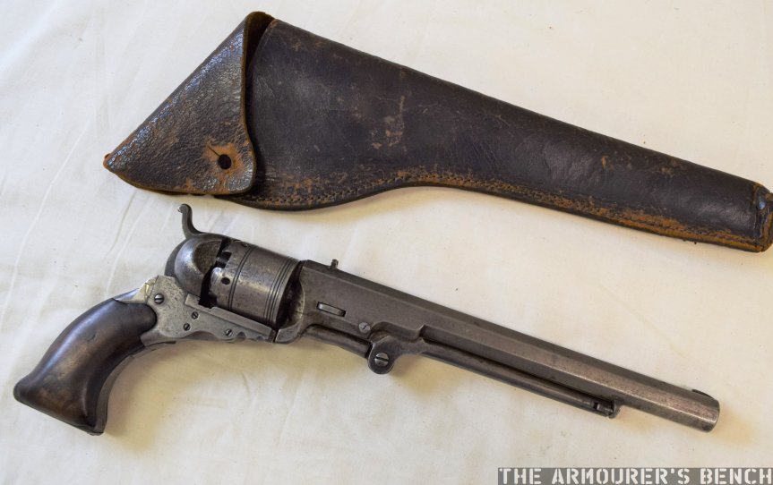
Adapted Colt Paterson No.5 Holster Model with contemporary holster (Photo: Matthew Moss, Courtesy of Cody Firearms Museum)
The Colt Paterson was an expensive item when it first appeared on the market, costing between $40 and $50 – well over $1,000 today. So then, as now, it makes sense that people who invested a considerable amount in a revolver would adapt and upgrade it if they could.
Below is another example of a Colt Paterson which was adapted. A No.5 Holster model, serial number 951, which had had its barrel cut down to 5 inches. This was done after it left the factory as the cut interrupts the original factory marker’s markings. The pistol also has a new cone front sight added.
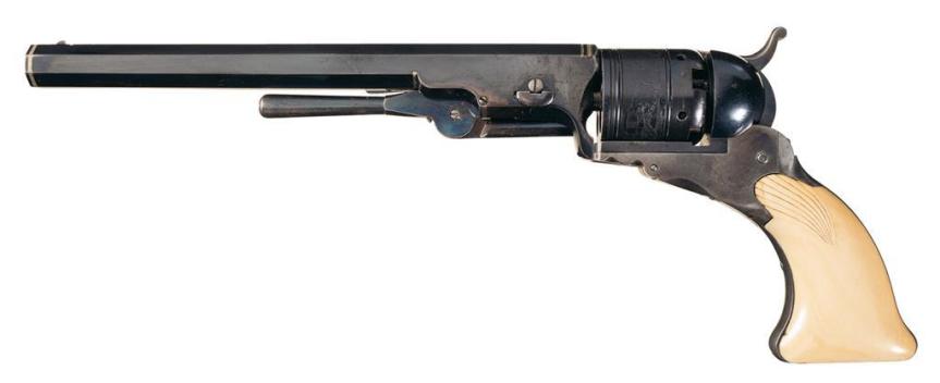
Adapted Colt Paterson No.5 with factory loading lever, with a shortened barrel and new front sight. (Rock Island Auctions)
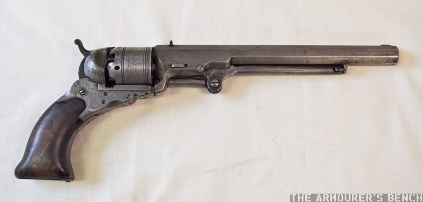
The pistol we are examining in this blog/video, is part of the Cody Firearms Museum’s collection – serial number 954. It had a number of alterations to the revolver, principally the addition of a captive loading lever and a new rear sight. While the Patent Arms Company had begun adding a loading lever to their revolvers in 1839, these were of a different style and shape. Below we can see two original examples of Patent Arms Company factory loading levers.
Colt Paterson with long loading lever and scalloped cutout to allow capping, Serial number 818 (Collector Firearms)Colt Paterson with a short loading lever, serial number 515 (Rock Island Auctions)
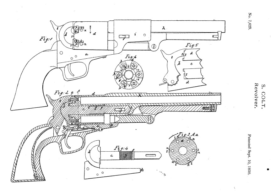
It appears that loading levers of different designs were used on the post-1839 Patersons. The top revolver appears to use a lever similar to the one later utilised in the Model 1847. Both of the examples above differ significantly to that seen on serial number 954 (below), which is more akin to the loading levers seen on the Colt Model 1848 Percussion Army Revolver (or Colt Dragoon) and the later Model 1851 Navy. The profile of the levers and design and location of the pivot point differ. They both also lack any retention point near the end of the lever. This would suggest that #954’s lever is not a factory addition but something which was added later, copying the 1851 Navy’s retained lever which was patented in September 1850 (US #7,629). On close examination the cap cutout at the rear of the cylinder and the cut into the barrel assembly just in front of the cylinder to facilitate loading appear to differ from Patersons with factory loading levers.
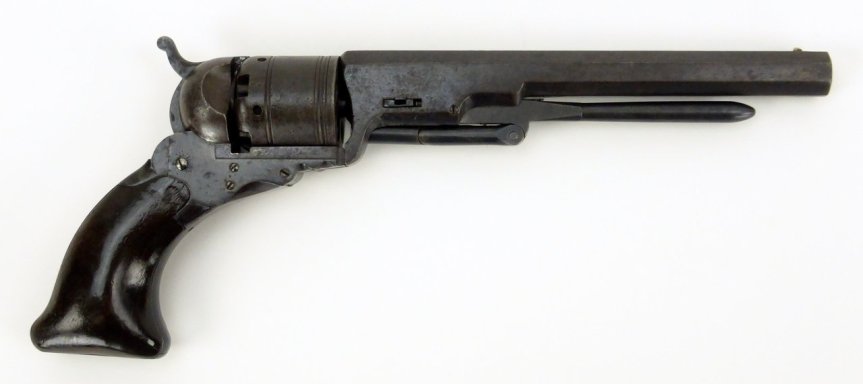
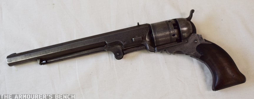
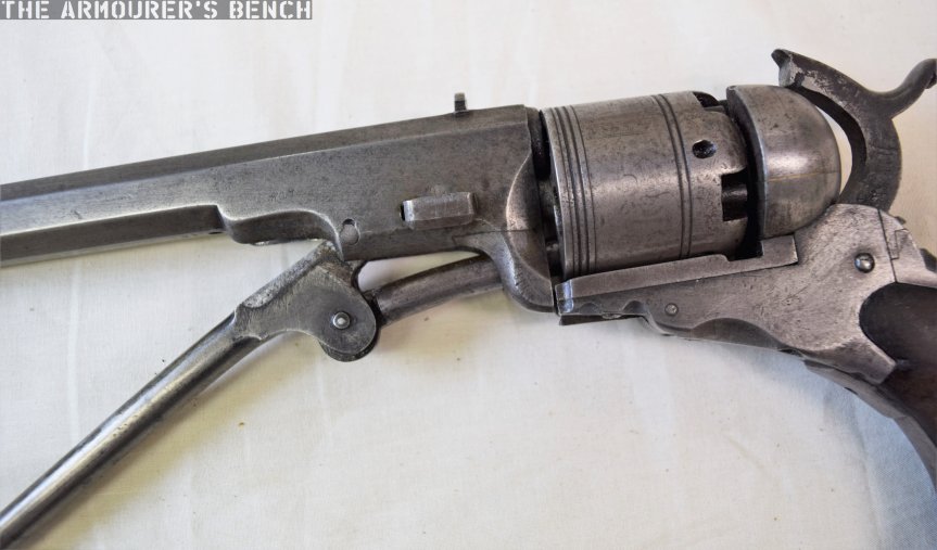
Colt Paterson No.5 serial number 954 held by the Cody Firearms Museum, note the 1851-style loading lever (Photo: Matthew Moss, Courtesy of Cody Firearms Museum)
A similar retention latch system can be seen in Colt’s 1850 patent:
Samuel Colt’s 1850 Patent, featuring a loading lever retention system (US #7,629)
As with other Colt percussion revolvers with loading levers, the rammer acts on the 6 o’clock cylinder. To load, the revolver was brought to half cock, powder was poured into the chamber, followed by round ball projectile. This was seated enough to allow it to line up with the rammer and the lever could then be pulled to ram the ball home. The cylinder could then be capped. The 1839 Paterson’s had a scalloped cutout to allow caps to be placed on the cylinder nipples without removing the cylinder.
Left-side view of the Colt Paterson No.5 (Photo: Matthew Moss, Courtesy of Cody Firearms Museum)
Interestingly the revolver has a slightly bent rammer but seems to function fine despite this. This is perhaps an indication of hand-fitting by the gunsmith who adapted the revolver.
Close up of the Colt Paterson at half cock, note the slightly bent rammer (Photo: Matthew Moss, Courtesy of Cody Firearms Museum)
At some point, perhaps at the same time as the fitting of the lever, a new set of sights were fitted. With a more prominent front sight and a rear notch sight added to the top of the barrel, just in front of the cylinder. This was a feature that the 1851 Navy did not have, and no Colt revolver would have until decades later. The gunsmith appears to have cut the dove tail for the sight though the original decorative scroll engraving surrounding the maker’s mark.
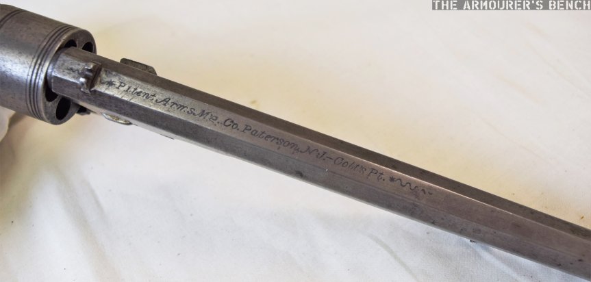
Close up of the revolver’s markers markings and added rear sight, which cuts through some of the original decorative scroll work (Photo: Matthew Moss, Courtesy of Cody Firearms Museum)
More Photographs of the Adapted Colt Paterson:
Adapted Colt Paterson No.5 Holster Model with contemporary holster (Photo: Matthew Moss, Courtesy of Cody Firearms Museum)
Close up of the Colt Paterson’s brazed on loading lever retention catch (Photo: Matthew Moss, Courtesy of Cody Firearms Museum)
Close up of the serial number, 954, on the CFM’s Paterson No.5 (Photo: Matthew Moss, Courtesy of Cody Firearms Museum)
The revolvers produced at the Patent Arms Company’s Paterson factory in the late 1830s and early 1840s date from a fascinating period of American history, on the cusp of an era dominated by Samuel Colt’s revolvers. While the exact circumstances of the adaptations/upgrades made to the revolver we have examined at the Cody Firearms Museum are unclear it tells us that Colt’s revolvers, even early examples, were highly prized.
If you enjoyed the video and this article please consider supporting our work here.
Specifications (for No.5 Holster model, #954):
Overall length: 13.5 in (35cm)
Barrel length: 8 in (20cm)
Calibre: .36
Capacity: 5-shot cylinder
Weight: ~2lb 10oz (1.2kg)
Bibliography:
‘Revolving Gun’, S. Colt, US Patent #9430X, 25 Feb. 1836 (source)
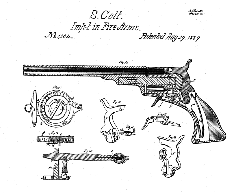
‘Improvement in fire-arms and in the apparatus used therewith’, S. Colt, US Patent #1304, 29 Aug. 1839 (source)
‘Improvement in revolving chambered fire-arms’, S. Colt, US Patent #7629, 10 Sep. 1850 (source)
During my recent research trip to the US I was lucky enough to handle and examine a lot of very interesting firearms. This short video is a bonus, while we were opening one of the cases at the Cody Firearms Museum to examine another firearm (that video is coming soon) I noticed a sectioned British Pattern 14 rifle, made by Winchester for the British government during the First World War. It was too good an opportunity to pass up so I filmed this quick video taking a look at the P14’s internals.
The P14 would go on to be the basis of the US M1917 rifle built by Winchester, Remington and Eddystone.
Cutaway of a Winchester-made Pattern 14, note the rear volley sight and sectioned magazine and chamber (Matthew Moss)
The cutaway shows the internals of the rifle’s actions as well as the barrel, chamber and magazine. It was cool to see a cutaway of the P14 up close and I couldn’t resist grabbing some footage.
My thanks to the Cody Firearms Museum, at the Buffalo Bill Center of the West, for allowing me access to their collection. You can find out more about the CFM here.