Bomarc Missile – The First Long Range Surface-to-Air Missile

The Boeing Bomarc was the world’s first long-range surface to air missile and despite its shortcomings remain in service for a decade. It was an extremely ambitious project and is a Cold War weapon that few today are familiar with.

In the late 1940s, Boeing began work on a surface to air missile – then described as a ‘pilotless interceptor’. The project was code-named MX-1599 and the Michigan Aerospace Research Center (MARC) joined Boeing to work on the programme.

DSC_0076wm
Boeing BOMARC at Hill Aerospace Museum (Matthew Moss)

The MX-1599 was to be a long-range supersonic nuclear-tipped surface to air missile (or SAM), detonated by a proximity fuse. The missile went through a number of official designations as it was developed during the 1950s – finally becoming known as the Bomarc – an acronym of Boeing and Michigan Aerospace Research Center.

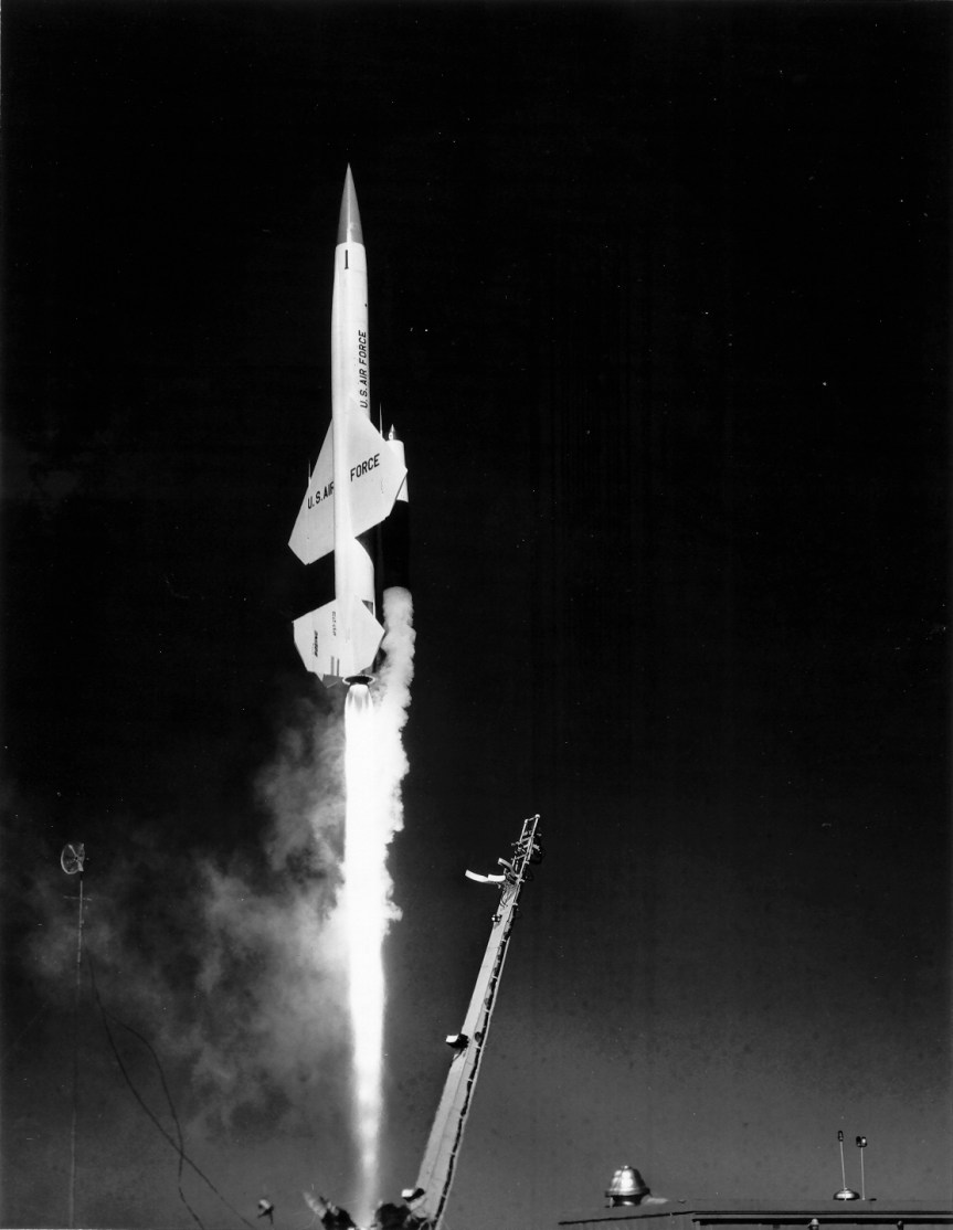
The Bomarc was launched vertically using rocket boosters, before its main ramjet engines took over, enabling it to cruise at Mach 2.5 (approx. 1,920 mph). The initial Bomarc A had a range of 200 miles with an operational ceiling of 60,000 feet.

It was ground controlled using NORAD’s Semi-Automatic Ground Environment (SAGE) system until it neared its target, when an onboard radar, a Westinghouse AN/DPN-34 radar, took over.

The Bomarc could be tipped with either a 1,000 lb conventional high explosive or low yield W40 nuclear warhead. These were detonated by a radar proximity fuse. The W40 had a yield of up to 10 kilotons, able to destroy entire formations of aircraft.

CIM-10_Bomarc_missile_battery
BOMARC Site No. 1 at McGuire Air Force Base (USAF)

The missile had a wingspan of just over 18 feet or 5.5metres, it was 45 feet or 13.7 metres in length and weighed approximately 16,000 lbs (7257 kg) on launch. The Bomarc’s first flight took place on 24th February, 1955.

The USAF intended to use the missile to engage incoming Soviet bomber formations and ICBMs. Originally planning for over 50 Bomarc launch sites, but only one was operational by 1959 and only eight were operational by the early 1960s. The upgraded Bomarc B was developed in the early 1960s, with an improved radar, a Westinghouse AN/DPN-53, and a greater maximum range of 430 miles, as well as a higher operational ceiling of 100,000 feet.

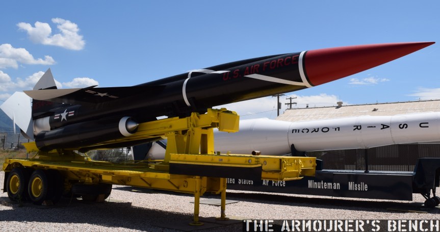
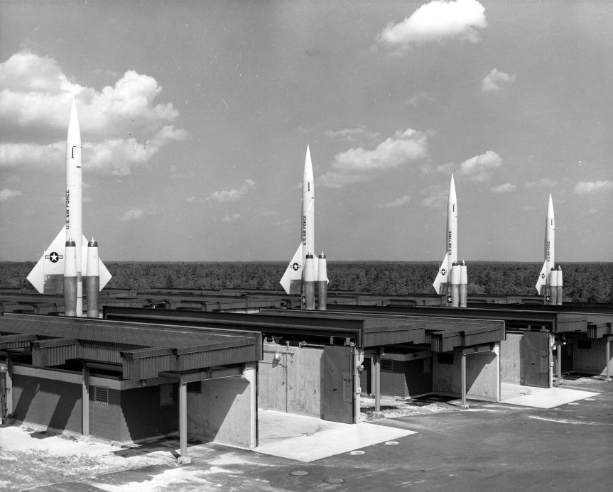
The Bomarc was stored horizontally in specially built semi-hardened bunkers and kept fuelled and ready to launch at a moment’s notice. When targets were detected the missile would be raised and launched vertically.

One of the dangers of keeping the missiles fuelled became clear in June 1960, when a nuclear-armed Bomarc A caught fire exploding the onboard tank and contaminated part of McGuire Air Force Base with melted plutonium. Despite this the missiles remained operational for over a decade with the first sites being deactivated in 1969 with the last stood down in 1972.

BOMARC (1)
BOMARC launching (USAF)

While the Bomarc missiles were the world’s first operational long-range anti-aircraft missile they were too slow to achieve operational readiness to keep pace with the rapidly changing nuclear threat – as both superpowers transitioned from bomber to ICBM-focused strategies. They were expensive to manufacture and difficult to maintain at readiness. In the late 1950s the Bomarc also embroiled in a war of words with the US Army arguing their short range Nike Hercules (SAM-A-25/MIM-14) missile was more effective. The Hercules remained in service through to the 1980s, albeit as a air defence missile – rather than targeting soviet ICBMs or bomber aircraft.

The Bomarc was an ambitious project when it began in the late 40s, but with technology and cold war nuclear strategy rapidly evolving the Bomarc was almost obsolete before it became operational. A total of 570 Bomarc missiles were built between 1957 and 1964 with the US and Canada (which led to considerable political controversy) being the only countries to deploy them.

I hope you guys enjoyed this look at the Bomarc, we’ll have a few more videos on missiles in the future.

If you enjoyed the video and this article please consider supporting our work here. We have some great new perks available for Patreon Supporters.


Specifications:

Wingspan: 18 feet 2 inches
Diameter: 35 inches
Length: 45 feet
Approx. takeoff weight: 16,000 pounds
Top speed: Mach 2.5
Range: 400 miles (IM-99B)
Ceiling: 100,000 feet
Power: 50,000-pound-thrust solid-fuel rocket (takeoff); two 12,000-pound-thrust Marquardt ramjet engines (cruise)
Armament: 1,000 lb conventional or 10 kiloton W40 nuclear warhead

Bibliography

IM-99A/B BOMARC Missile, Boeing, (source)
Nuclear Weapons of the United States: An Illustrated History, J.N. Gibson, (1996)
Nike Historical Society (source)
Supersonic Guardian, Boeing film, c.1960 (source)

The Bomarc featured in the video is part of the Hill Aerospace Museum’s collection.

Browning Prototypes – Detachable Box Magazine Lever Action Rifle

The rifle we’re examining is one of dozens of designs sold by the Brownings to the Winchesters Repeating Arms Company during their long relationship. This design dates from the early 1890s and represents one of Browning’s numerous attempts to move away from the tube magazine-fed designs favoured by Winchester.

The prototype is based around the lever-actuated vertically sliding locking block patented by Browning in May 1884 and first used by Winchester in the Model 1886. The rifle itself is in the ‘military musket’ configuration with full-length handguards, military sights, a cleaning rod and able to mount a bayonet.

DSC_0590
Right side of the rifle (Matthew Moss)

The rifle is chambered in a .45 calibre cartridge, likely .45-70, and weighs just over 9lbs. Browning patented the design of the rifle and magazine in August 1891, with the patent being granted in December (US #465339). It is attributed to John Moses Browning and his younger brother Matthew S. Browning.

The most interesting feature of the rifle is its detachable box magazine. The magazine is held in place by a spring-loaded catch at the front of the magazine which locks against a tab in the magazine’s wall.

DSC_0577
A close up of the magazine well, note the added metal lip of the front of the well, not a part of the receiver (Matthew Moss)

It differs from the box magazines previously developed by James Paris Lee, which Lee begun developing in the mid-1870s (see examples listed below). It’s a simple design with a follower powered by a coil spring. The prototype mag itself is made from pressed metal and is held together with some rough welds. Unlike the magazines we’re familiar with today, the top of the Browning’s magazine is almost entirely enclosed with only a small opening at the rear. The rounds would be loaded nose-first with their rims sliding into the channel at the rear of the magazine.

DSC_0580
Close up of the magazine removed from the rifle – right side (Matthew Moss)
DSC_0586
A view of the top of the magazine with the small opening and notch for the cartridge rime visible (Matthew Moss)

The single-stack magazine appears to hold around five rounds, with Browning’s patent supporting this. The position of the magazine, in front of the action – not below it, is a hint at how it worked. An almost fully enclosed magazine does have its advantages – it would have prevented dirt from entering the mag and it also overcame the need for feed lips which were susceptible to damage, one of the elements which took Lee some time to perfect.

DSC_0582
A close up of the front wall of the magazine, note the locking notch (Matthew Moss)

So How Did The Magazine Work?

There is a shoulder on the underside of the bolt which caught the rim of the cartridge which was protruding from the magazine. The bolt pulled the cartridge backwards, out of the magazine and onto a cartridge lifter. As the lever reached its full forward travel the lifter then elevated the round up into line with the breech. When the lever was cycled back again the round was pushed off the lifter and chambered, just as in a normal tube-fed Winchester. As the lever reached the end of its return travel the locking block rose to locked the action.

US465339-drawings-page-2
The Browning’s 1891 patent for the magazine, note ‘h‘ is the shoulder which pulled rounds out of the magazine (US Patent Office)

The prototype has a sliding safety bar that locks the lever and blocks the trigger. The trigger differs from the Model 1886 as it is integrated with the lever. In the photograph below we can see the locking block descended, with the lever forward, and the breech block to the rear with the action open. We can also see the striker assembly at the rear of the bolt. The striker cocks on closing when the lever is returned rearward.

DSC_0595
The rifle with its action open, bolt o the rear and lever forward. Note the striker assembly at the rear of the bolt (Matthew Moss)

It’s quite an exposed action, with the entire top of the action open. With the action closed in the photograph below we can see the extractor running along the right side of the bolt.

DSC_0572
A close up of the rifle’s receiver which is still ‘in the white’ (Matthew Moss)

It’s clear from the design of the magazine that Browning didn’t intend the rifle to be reloaded with stripper clips, although single loading of the rifle itself (not the magazine) would have been possible. When compared to other contemporary system this would have been somewhat of a disadvantage compared to Lee’s magazine’s later loading with chargers and stripper clips. However, from examination of Browning’s 1891 patent his intention becomes clear, the patent explains that he intended for the magazine itself to be replaced:

“One magazine may be readily removed from the gun and another introduced in its place, so that the person, using the arm may have at hand several magazines to be interchanged as the cartridges from one magazine are exhausted.”

This is a concept that wouldn’t be accepted by militaries for decades. Winchester purchased the rights to the design but this was one of many designs Browning sold the company which never saw production. The design and prototype are fascinating and represent one of Browning’s lesser-known concepts.

DSC_0591
Left side profile of the rifle (Matthew Moss)

This rifle is a unique prototype and it was a true honour to examine it. It’s now on display at the newly refurbished Cody Firearms Museum, at the Buffalo Bill Centre of the West. The new museum is phenomenal and well worth a visit. Our thanks to the museum for allowing us to film items, like this one, from the museum’s collection.

If you enjoyed the video and this article please consider supporting our work here. We have some great new perks available for Patreon Supporters.


Bibliography:

‘Magazine Gun’ J.M. & M.S. Browning, US Patent #465339, 15 Dec. 1891 (source)

John M Browning: American Gunmaker, J. Browning & C. Gentry (1964)

Some of James Paris Lee’s magazine patents, for comparison:

‘Improvement in Magazine Fire-arms’, J.P. Lee, US Patent #221328, 4 Nov. 1879 (source)

‘Magazine For Fire Arms’, J.P. Lee & L.P. Diss, US Patent #295563, 25 Mar. 1884 (source)

‘Magazine Fire Arm’, J.P. Lee, US Patent #383363, 22 May, 1888 (source)

‘Gun Magazine’, J.P. Lee, US Patent #627824, 27 Jun. 1899 (source)

Matt on Forgotten Weapons!

Last month while Matt was visiting the Cody Firearms Museum for their Arsenals of History Symposium he had the pleasure of meeting lots of great people from the historic firearms world. One person he met was none other than Ian of Forgotten Weapons.

Ian was kind enough to suggest doing an interview to share and highlight our work here at TAB with his subscribers. Matt discussed the idea behind TAB and some of the things that we cover.

We very much appreciate Ian’s support of our project and opportunity to chat on camera about our work. Thanks Ian!

Live Fire: Shooting the M1917 at 700 Yards

A month ago I posted a short video from a range trip shooting the Remington M1917 at about 100m, getting a feel for the rifle and checking zero. I said in that video that I was planning on stretching the M1917s legs in the near future and last week I got the chance. I had the opportunity to shoot the rifle out to 700 yards (640m) which was a lot of fun.

rrem_soft
The view down range from the firing point (Matthew Moss)

With some 147gr S&B I managed a half decent score only missing twice out of 20 rounds. I’ve never shot out to 700 yards especially not with iron sights so it was a fun challenge, amazingly my last round was a bull, which was a real bonus!

If you enjoyed the video and this article please consider supporting our work here. We have some great new perks available for Patreon Supporters.

Webley-Bentley Percussion Revolver

During a recent visit to my local gun shop, I was having a look through one of their cabinets when I spotted something interesting. A Webley-Bentley Revolver from the mid-1850s.

nor_soft
Right side of the revolver (Matthew Moss)

The Webley-Bentley was a double-action only, or as it was then known ‘self-cocking’, percussion revolver and a contemporary of the Adams revolver. Based on lock-work designed by Joseph Bentley the revolver was offered in a series of calibres. The Webley-Bentley was introduced in the mid-1850s and continued to be produced into the 1860s. This particular pistol was sold by R. Jones of Liverpool – remarkably the gun has stayed local for 160 years.

nor_soft
You can just make out the faint remains of the merchant’s mark – ‘R. Jones Liverpool’ (Matthew Moss)

The pistol is a .36 calibre open-top revolver, with a 5-shot percussion cylinder and a hexagonal barrel. On the left side of the pistol is a James Kerr-style rammer for loading. It’s hammer is spurless and the action is double action only. The revolvers also came in larger calibres like .40 and .45.

nor_soft
Left side of the revolver (note the rammer and spring catch) (Matthew Moss)

The overall condition of the revolver wasn’t great, but it had that worn patina of a gun that’s seen some use, which is a charm in itself. The cylinder pawl was a little worn and the timing was a little off, but it still worked and the main spring was strong. On the left side of the revolver is a flat spring catch, held to the frame by a screw, that enables the hammer to be set at half cock, for loading. In this example the post that interfaces with the hammer has long since worn. 

Of course Webley have since become best known for their line of top break, centre-fire revolvers which were used extensively by the British Army but it was interesting to get a look at one of their earlier pistols.

If you enjoyed the video and this article please consider supporting our work here.


Bibliography:

Webley Revolvers, G. Bruce & C. Reinhart (1988)

The Webley Story, W.C. Dowell, (1962)

‘Improvements Aplicable to Fire-Arms’, J. Bentley, UK Patent #960, (04/12/1852)

Car vs Train (1919)

Following on from last week’s episode on massive US Railway Guns, I thought we’d stay with the railroad/railway theme but stepping away from our figurative Armourer’s Bench for a moment to appreciate some really incredible contemporary footage.

While I was doing research for our earlier video on the M1918 Ford Light Tank, I came across this amazing footage filmed by the Ford Motor Company in 1919. It shows what appears to be a Ford Model T Touring car being hit by a train. The result, as expected, is carnage.

The footage, which is clearly staged, was filmed for a traffic safety film by Ford in 1919. While the scenario might be staged, the results certainly are not.

If you enjoyed the video and this article please consider supporting our work here. We have some great new perks available for Patreon Supporters.


Bibliography:

Traffic Safety and Ford Automobiles, US National Archives, (source)

US Military Railway Guns In Action

While doing some research in the US National Archives’ online catalogue I came across a very interesting video composed of footage from a couple of US Army Ordnance demonstrations so I thought I’d take the opportunity to talk about some very big guns.
Railway guns emerged during the late 19th century as a way of moving massive, large calibre guns which had a reach far beyond that of field artillery. Before aircraft were able to effectively attack behind enemy lines railways allowed armies to bring huge guns within range and harass their enemies lines of communication and supply.
This footage comes from Ordnance demonstrations at the Aberdeen Proving Ground in the early 1920s.

New Movie (5).Movie_Snapshot
16in Coastal Gun (US National Archives)

First up we have a US-built copy of the French 305mm Canon de 305 modèle 1893/96 à glissement, which according the original footage notes, was a 10in sliding mount for a gun firing a 150lb projectile. I also found some contemporary images of the gun being built at the US Watertown Arsenal, in Massachusetts, which describes it as the Model 1919. It may be the only example built by the US, Schneider built 8 of these guns for France during the war.  When the gun fires we can see the whole gun and carriage recoil back a meter or so. Guns on sliding mounts cant be traversed and have to be aimed with specially laid track.

111-SC-46528
M1895 12in Coastal Gun in a ‘disappearing#’ mount (US National Archives)

Next we have a 12 inch M1895 gun, mounted on a M1918 railway carriage which was based on the French Batignolles mount, with 360-degree traverse. Originally designed as a coastal defence gun, here’s a photograph taken in 1918 of the gun firing from a disappearing mount.
The M1895 had long been used as a coastal defence gun, and with US entry into the war surplus or unnecessary coastal guns were remounted as railway guns. The railway mounted M1895s had a large recuperator to mitigate the gun’s recoil. 12 were mounted, however, none reached France before the end of the war. We also get a nice shot of the shell hitting its target in the distance.

111-SC-46247
A 14in Railway Gun in Bassens, France c.1919 (US National Archives)

The 14 inch railway guns were the only big US guns to see action during WW1. Taking spare US Navy 14in naval guns, the 14″/50 caliber Mk 4 gun, which had been mounted in the New Mexico and Tennessee-class battleships, and mounting them in a carriage built by the Baldwin Locomotive Works. Once in position the guns had to have a recoil pit dug out beneath the carriage to allow space for the gun to recoil when it was at high elevation. They had a range of up to 25 miles.
Five Mk1 guns made it to France operating as single gun batteries manned by US Navy Sailors. The guns fired a total of 782 shells during the war, with Battery 4 firing its last shell at 10:57:30 a.m. on 11 November 1918.

Unlike the MkI guns that made it to France in this footage we see the gun without an armoured gun house, with the gunners working the gun in the open.

16 inch Gun M1919 clip 1 111-h-1246-r1_HD_2Mbps_Trim_Moment
An M1919 16in Coastal Gun in a Barbette mount (US National Archives)

Finally, we have the truly massive 16 inch M1919 coastal gun . Designed for the Army Coast Artillery Corps to defend the US’ major coastal ports the 16-inch gun could throw a 2,340 lb shell up to 28 miles. In this footage we can see the gun mounted on an M1919 barbette carriage which could be elevated up to 65-degrees.
This second piece of footage dates from between 1929 and 1931, with dozens of West Point cadets gathered eagerly to see the gun in action.

If you enjoyed the video and this article please consider supporting our work here. We have some great new perks available for Patreon Supporters.


Bibliography:

Demonstration of Ordnance Materiel at Aberdeen Proving Grounds, 1920-1926 (source)

Railway Artillery: A Report on the Characteristics, Scope of Utility, Etc., of Railway Artillery, Vo.1, H.W. Miller & US Ordnance Dept. (1921) (source)

Railway Artillery: A Report on the Characteristics, Scope of Utility, Etc., of Railway Artillery Vol.2, H.W. Miller & US Ordnance Dept. (1922) (source)

The United States Naval Railway Batteries in France, E. Breck (1922) (source)


Rheinmetall G3

We’re all familiar with the Heckler & Koch G3 and its roller-delayed blowback action. What is less well-known is that H&K were one of two companies originally contracted by the West German government to produce the Bundeswehr’s new service rifle. The other company was Rheinmetall and today we’re lucky enough to be taking a look at an example of an early production Rheinmetall G3.

Left side (courtesy of the Cody Firearms Museum)

The rifle which became the G3 was of course originally developed by German and Spanish engineers working at the Centro de Estudios Tecnicos de Materiales Especiales (CETME) and was intended to equip the Spanish armed forces. Initially, the West German Bundesgrenzschutz (border guards) were interested in purchasing a substantial number of the new CETME rifles, with an initial order for 5,000 agreed, however, in September 1955 the order was cancelled due to delays in production and the Bundesgrenzschutz subsequently ordered the FN FAL instead.

In November 1955, the Bundeswehr (West German military) was formed and began to search for a suitable new 7.62x51mm service rifle. Having observed the Bundesgrenzschutz’ testing the fledgling Bundeswehr took an interest in the CETEME rifle. 400 ‘STG CETME’ rifles were ordered for troop trials and these were assembled in Germany by Heckler & Koch. The rifles were delivered in late 1956, and comparative trials against the FAL began the following year.

2015-06-05 13.18.23
CETME Model A (Courtesy of P. Hokana)

The trials found the ‘STG CETME’ to be satisfactory in terms of features and design but lacking in durability. A number of small changes were requested including a flash hider suitable for launching rifle grenades, either a flip-up or dioptre rear sight instead of a traditional tangent style, a case deflector, a simpler more ergonomic pistol grip, a longer more ergonomic cocking handle, changes to the recoil spring guide and tweaks to the shape of the buttstock. Additional improvements such as a stronger bipod, lighter magazine, a last round hold open mechanism, overall lightening of the rifle, a lighter 20-round magazine and a proper handguard were also requested.

DSC_0039
Left-side of the G3’s receiver, note the partial reinforcing rib on the magazine housing (Matthew Moss)

FN were unwilling to grant Germany a manufacturing license and the $110 per rifle price for the FAL proved substantially higher than CETME’s production estimates (The ArmaLite AR-10, J. Putnam Evans (2016), p.204). With adoption looking likely, legal wrangling over patent ownership began between Mauser, Rheinmetall and Heckler & Koch. All claimed the ownership of the roller-delayed blowback principle used by the CETME rifle. Eventually, however, the West German government awarded Rheinmetall and H&K future production contracts for the new rifle with the government supporting H&K’s claims but the legal battles continued for almost a decade.

In the meantime, with production of the CETME rifle not yet initiated and in light of some durability/reliability issues suffered during the STG CETME’s troop trials, 100,000 ‘Series C’ FN FALs were ordered for the Bundeswehr in late 1956. In 1957 the Swiss SIG 510 (designated the G2) and the American ArmaLite AR-10 (designated the G4) were also evaluated. Once the modifications requested after the troops trials were completed by H&K, a run of twenty rifles was produced and tested again.

DSC_0047
A view inside the ejection port of the G3 with the charging handle locked back (Matthew Moss)

In 1959, the West German government finally adopted the CETME rifle, designating it the G3. The German federal government decided that they wished to purchase the worldwide manufacturing rights to the G3, which naturally the Spanish government was reluctant to agree to. An agreement was finally reached in January 1958 and the contract giving West Germany worldwide rights to the G3 was finalised on February 4th, 1959.

One issue was that in June 1957, CETME had agreed a licensing deal for manufacture and sale of the rifle with a with a Dutch company Nederlandsche Wapen en Munitiefabriek (NWM). In order to gain the manufacturing rights sold to NWM the German government awarded the Dutch company a lucrative contract producing 20mm ammunition (Full Circle, p.234).

DSC_0045
A close up of the trigger mechanism housing, note ‘Germany’ faintly scratched into the surface (Matthew Moss)

Interestingly, as the German government owned the manufacturing rights, H&K initially had to pay the government 4 Deutsche Marks per rifle, despite having been awarded the contract by the German government. In late January 1959, H&K were awarded the first substantial production contract, amounting to 150,000 rifles. Rheinmetall were subsequently awarded a similar contract (Full Circle, p.235).

According to R. Blake Stevens’ book on the roller-delayed blowback action, Full Circle, Rheinmetall produced 500,000 G3s during the 1960s, delivering 8,000 rifles per month (Full Circle, p.287). As H&K had been designated as the technical lead on the G3 project, Rheinmetall’s engineers made no attempts to develop modifications or improvements and even when H&K had switched to plastic furniture the Rheinmetall guns continued to use wood. Rheinmetall’s only other G3-related project was the RH4, a 7.62x39mm chambered, roller-locked but gas-operated rifle designed for export (Historical Firearms).

Bundeswehrsoldaten_während_eines_Manövers_(1960) - Copy
W. German Army Armoured Reconnaissance car, with MG3 team with No.2 armed with G3, c.1960 (US Army)

In addition to the G3, Rheinmetall were the sole manufacturer of the MG3 machine gun, the 7.62x51mm MG42. Blake Stevens explains that in 1969, when a new tender for MG3 production was due, that H&K moved to undercut Rheinmetall who had until now held the monopoly on MG3 production (Full Circle, p.292). As a result an agreement was reached where Rheinmetall retained their monopoly on MG3 production and H&K became sole manufacturer of the G3 for the West German military.

Examining An Early Production Rheinmetall G3

The G3 went through a large number of changes both before and after it went into service. The rifle we’re examining today is a good example of an early production rifle, as adopted in 1959. This rifle is lightly marked with ‘G3 [Rheinmetall’s ‘star-in-a-circle’ logo] followed by a serial number of 745 and below that it is date marked with the ‘3/60’, for March 1960.

DSC_0043
A close up of the G3’s front sight and sling attachment point (Matthew Moss)

Working our way from the muzzle back; the rifle has the early style of flash-hider/grenade launcher support which was introduced in 1957 and altered in early 1961, an enclosed front sight and a detachable bipod (which was not Bundeswehr general issue). It has a stamped metal handguard which was replaced by one with a wooden insert in 1961, before H&K introduced plastic furniture in 1964.

DSC_0065
The G3 field stripped (Matthew Moss)

The folding carrying handle seen on the troop trials rifles has been removed, the receiver is stepped for the attachment of a scope base and the magazine housing has a single strengthening rib, rather than the later ‘full-frame’ continuous rib. It has an S-E-F selector (S – Sicher/safe, E – Einzelfeuer/semi, F – Feuerstoß/auto) and black plastic pistol grip. Internally, the rifle has a captive mainspring. Unlike later G3’s the rifle has a 2-position folding L-shape rear aperture sight with apertures for 200 & 300 metres rather than the later dioptre sight adopted officially in mid-1960. The rifle has a wooden stock held with a stamped metal sling attachment and a plastic buttplate.

If you enjoyed the video and this article please consider supporting our work here. We have some great new perks available for Patreon Supporters.


Specifications:

Overall Length: 40 in /1.2m
Barrel Length: 17.7in / 45cm
Weight: 8.6lbs / 3.6kg
Action: Roller-delayed blowback
Capacity: 20-round box magazine
Calibre: 7.62x51mm


Bibliography:

HK G3 Operator’s Manual – early 1970s (source)

Full Circle: A Treatise on Roller Locking, R. Blake Stevens (2006)

The ArmaLite AR-10, J. Putnam Evans (2016)

The CETME Assault Rifle, Small Arms Review, J. Huon, (source)

Our special thanks to the Cody Firearms Museum, at the Buffalo Bill Center of the West, for their kind permission to film items from their collection and their assistance in filming and research.

Ford M1918 Light Tank- America’s First Tank

When the US entered World War One in April 1917, the US Army had no experience with tanks. American observers in France had reported on the early Allied uses of tanks at the Somme and American enthusiasm for the new machines was lacking in many of the Army’s upper echelons.

This began to change after the arrival of General Pershing and his staff in France, ahead of the American Expeditionary Force. Pershing directed that a Tank Corps be raised and detailed a number of officers, including the enterprising young officer, Captain George S. Patton, to establish a training ground and report on how best to deploy tanks.
Patton was instrumental in shaping the US Army’s early tank doctrine, he wrote a highly detailed report on how to deploy tanks to maximum effect. Patton, a cavalry officer by training, admired the French Renault FT’s speed, mobility and manoeuvrability but felt the two doctrines of French light and British Heavy tanks could be combined. In December 1917, Colonel Samuel Rockenbach was placed in command of the new, but still tank-less, US Tank Corps.

165-WW-313A-003
A Ford Model 1918 Light Tank, weighing 3 tons it was armed with a single .30 calibre machine gun (US National Archive)

Britain and France shared their tank designs with the US but in early 1918, the American automobile giant, Ford, began work on an American light tank. The result was a light and mobile tank weighing in at 3 US tons (or 2.7 metric tons). Sometimes referred to as the Ford 3-Ton Tank or the Ford Model 1918. Ford hoped to produce the new tank using as many off the shelf components, from their automobile and truck production, as they could. So the new tank was powered by two 4-cylinder Ford Model T engines, in theory developing around 40 horsepower, with a maximum speed of 8 mph and an operational range of just over 30 miles. Taking cues from the French FT, the M1918’s engines, fuel tank and transmission were mounted in a compartment at the rear of the tank. Some sources note that the tank was developed with the assistance of the Van Dorn Iron Works, in Cleveland, Ohio, presumably assisting in the manufacture of bullet-proof steel plates making up the tank’s armour.

165-WW-313A-064 - Copy
An early version of the 3-Ton Ford being assembled in one of Ford’s Detroit workshops (US National Archive)

Contemporary photographs show the prototype during assembly in one of Ford’s Detroit workshops. We’re extremely lucky to have these photos showing the development process, they show that the initial shape and layout changed very little but some important changes were made as the tank was tested. The photographs date to April 1918, suggesting that by late spring the first prototype was assembled.

Like the French FT, the M1918 had a two-man crew but was significantly lighter weighing 4 tons less. The Ford could reach speeds of up to 8 mph while the slower FT could achieve around 5 mph. The Ford M1918 was 14 feet (or 4.3m) long, making it slightly shorter than the FT. The Ford’s armour was much thinner than its French counterpart, while this helped with weight, it would have left the crew vulnerable. It had just 7 to 13mm of armour compared to the FT’s 8 to 22mm. The tank’s tracks were also extremely narrow, and while the tank was light, this could have conceivably led to issues with getting bogged down in thick mud. Some of the contemporary footage of the prototype shows it with wider, more practical looking, tracks but the later pre-production models seem to have reverted to the narrower tracks.

165-WW-303A-116 - Copy
The M1918 was powered by a pair of 4-cylinder Model T engines (US National Archive)

The earlier prototype Ford tank did not have a gun fitted and the front doors for both driver and gunner were hinged at the sides, rather than at the top. Some of the contemporary footage shows the gun-less prototype becoming trapped nose-up, at an almost 90-degree angle, after trying to cross a relatively narrow trench. To prevent this we see that the later tanks were subsequently fitted with a ‘trench tail’.

In terms of armament, the Ford was also limited with a single .30 calibre machine gun, mounted on the right side of the hull in an armoured casement. The casement doesn’t appear to have a prominent sight aperture or vision slit for the driver so how the gun was aimed is unclear. The gun also appears to have a very limited firing arc compared to the FT’s turret mounted gun, which could rotate a full 360 degrees. It is unclear exactly what sort of gun was going to be mounted in the tank although an Hotchkiss M1909 Benét–Mercié (also used in British tanks) may have been an option. Another more likely option would have been the specially-developed M1919 air-cooled Browning Machine Gun, which had been specially developed for tank mounting. Judging from the size of the armoured housing for the gun, however, it may have been intended to mount the M1918 Marlin Tank Machine Gun, which had large aluminium cooling fins.

165-WW-313A-004 - Copy
If we look closely we can see that the gunners hatch appears to be hinged, suggesting it can be opened too. Just to the right of the gun there is a round hole in the armour with what appears to be a starting handle sticking out of it (US National Archive)

The Ford had a two-man crew with the driver on the left and a gunner on the right. The driver also had a cupola, with vision slits, on the roof of the tank which allowed him to drive when the hatch was closed. But this must have been difficult to see out of unless the driver changed his driving position.

The tank had an exposed front axle connecting its large front track idlers, this would have been susceptible to damage from enemy fire and from hitting obstacles. At the rear is the drive sprocket and along the body of the tank are two sets of three suspension wheels with two track support rollers above. Note that the support rollers are mounted on a truck leaf spring, another example of off-the-shelf parts being utilised. This represents a change from the single support roller seen in the earlier prototype

The later footage shows as many as half a dozen pre-production tanks on the move during a demonstration at Ford’s plant in Detroit. We get a good feel for how fast and manoeuvrable the Ford tanks were. But they also struggle to navigate some of the more difficult terrain and don’t appear to have the power or traction to tackle some of the steeper hills or ditches. The tanks much have been difficult to steer, likely using a pair of clutch levers to control the tracks on either side. Two tanks even collide with each other and there’s a couple of other near misses as the Ford’s navigate around the test area. One tank becomes stuck requiring two others to pull it clear of the bank.

165-WW-313A-020 - Copy
Six pre-production Ford M1918s lined up before a demonstration (US National Archive)

The War Department was eager to get tanks into production ordering 15,000 M1918s from Ford, with 500 to be delivered in January 1919 with production continuing at 100 per day after that. An initial batch of 15 were ordered for testing. At least one of these was sent to France for evaluation before the end of the war. The French were unimpressed finding it inferior to the FT, they did consider it as an artillery tractor for the French 75. The US also considered the Ford for this role and some photograph captions from early 1919, of Battery A, 140th Field Artillery, describes it as a ‘3-ton tractor’ for pulling “the new American 75mm split trail gun”, the M1916. These photographs also prove that more than one M1918 reached France.

111-SC-51469 - Copy
Several Ford M1918s in use as ‘3-ton tractors’ for pulling the M1916 75mm gun, taken at the Artillery Training School in Le Valdahon, in 1919 (US National Archives)

The Ford tanks were not well regarded by those with practical experience, with the men of the US Tank Corps in France not consulted about the tank before it was ordered by the Ordnance Department. The war ended before large scale production of the M1918 could begin, With just 15 M1918s built we’re lucky to have this much film of it in action. Today only two of the Ford light tanks survive in US Army collections.

165-WW-319A-078.jpg
A post-war development of the Ford, note the slightly different gun mount, now in a ball mount with a prominent aiming aperture, this photograph was tank in early 1919 – gun type unknown (US National Archives)

In reality the M1918 was more a Machine Gun Carrier than a tank. How effective it might have been is a matter of speculation. It’s difficult to say, while the French may not have felt it was an improvement over the FT, it certainly showed enough merit for the War Department to make a large order. Its narrow tracks, lack of protection and minimal armament may have proved to be problems. The M1918’s real legacy is that it while the US had built other tanks during the war, including the M1917, a copy of the FT, and the MKVIII heavy tank, in collaboration with the British, the M1918 Ford was the first truly American designed and built tank.

If you enjoyed the video and this article please consider supporting our work here. We have some great new perks available for Patreon Supporters.


Specifications:

Length: 14 feet / 4.3 metres
Height: 5.9 feet / 1.8 metres
Width: 5.9 feet /1.8 metres
Weight: 3 US tons / 2.7 metric tons
Powerplant: 2 Ford Model T 4-cylinder engines producing ~40HP
Speed: 8mph
Armour: 7 – 13mm
Armament: .30 calibre machine gun, likely M1918 Marlin Tank Machine Gun or M1919 Browning Tank Machine Gun


Bibliography:

Primary Sources:

All photographs and footage was sourced from the US National Archives.

Contemporary Footage:

https://catalog.archives.gov/id/7419799
https://catalog.archives.gov/id/7419811
https://catalog.archives.gov/id/7419095
https://catalog.archives.gov/id/7419804
https://catalog.archives.gov/id/7419628
https://catalog.archives.gov/id/7419174
https://catalog.archives.gov/id/89506
https://catalog.archives.gov/id/24823
https://catalog.archives.gov/id/24615

Contemporary Photographs:

https://catalog.archives.gov/id/45506351
https://catalog.archives.gov/id/45508549
https://catalog.archives.gov/id/45508547
https://catalog.archives.gov/id/45508551
https://catalog.archives.gov/id/45508430
https://catalog.archives.gov/id/45508545
https://catalog.archives.gov/id/45508428
https://catalog.archives.gov/id/45508446
https://catalog.archives.gov/id/45508462
https://catalog.archives.gov/id/45508450
https://catalog.archives.gov/id/45508448
https://catalog.archives.gov/id/45508444

Secondary Sources:

The Illustrated Encyclopaedia of Military Vehicles, I.V. Hogg & J. Weeks (1980)
The Complete Guide to Tanks & Armoured Fighting Vehicles, G. Forty & J. Livesey, (2012)
Camp Colt to Desert Storm: The History of U.S. Armored Forces, G.F. Hofmann & D.A. Starry (1999)
The Machine Gun: History, Evolution, and Development of Manual, Automatic, and
Airborne Repeating Weapons, G.M Chinn (1951)

Live Fire: Bren Mk1 (Modified)

Introduce in British service in 1938, the Bren remained in use into the 1990s. Based upon the Czechoslovakian series of ZB light machine guns, its name comes from an amalgamation of its origins: BR for Brno, the factory in Czechoslovakia, and EN for RSAF Enfield where it had been adapted for British service and was to be produced.

The Bren is chambered in .303, is gas operated and fires from an open bolt. It feeds from a top-mounted 30 round box magazine, as such the sights are offset to the left meaning the Bren can only be fired from the right shoulder – which as a lefty, I quickly realised.

DSC_0454.JPG
Bren Mk1(Modified) (Matthew Moss)

This example does not have the scope mounting dovetail machined into the left side of its receiver, or the folding grip and the hinged shoulder rest indicating that it is a Mk1 (Modified) ‘Pattern A’ gun, which was introduced after the evacuation of Dunkirk, the British Expeditionary Force lost most of the 30,000 Brens that had been taken to France. Only around 2,000 remained in inventory in the summer of 1940, so increasing production was essential, this model and the even more simplified MkII were introduced. While at the same time the BESAL light machine gun was developed as an emergency alternative by BSA – check out our earlier video on the BESAL here.

DSC_0829
The BSA-developed BESAL light machine gun (Matthew Moss)

As a Mk1, the gun has the original profile buttstock, with the fitting for a rear folding grip and tripod attachment point as well as a buttcap. It also has the drum rear sight rather than the later ladder sight of the Mk2 & 3. It also had a folding cocking handle and this Mk1(M) gun also has the earlier pattern height adjustable, rather than fixed, bipod legs. This gun is marked ‘MK1, with an E within a D, 1942’ indicating it was made at RSAF Enfield.


DSC_0451
Bren Mk1(Modified) with magazine off and dust cover closed, note the drum sight but lack of receiver cut for optic (Matthew Moss)

The Bren’s relatively slow rate of fire (of around 500 rounds per minute) makes it controllable and very easy to fire single shots while in full auto. The Bren does, however, have a selector on the left side of the gun, just above the trigger guard, which can be set to safe, semi or fully automatic. The Bren has a rocking recoil impulse as its heavy bolt moves back and forth, easily manageable if held tightly into the shoulder with the off-hand holding onto the wrist of the stock. The top-mounted magazine when fully loaded does have a tendency to want to fall to the side but once you’re used to this it’s not really an issue. The legend surrounding the accuracy of the Bren is certainly somewhat valid, at the time it was recognised as an accurate weapon and I found it accurate from my short time behind the trigger.  I found the Mk1’s rear sight aperture and drum adjustment easy to use.

Spent cases eject out of the bottom of the receiver, the weapon had a sliding dust cover for when the magazine was removed and the charging handle is non reciprocating and folds forward.

DSC_0456
Bren Mk1(Modified) with magazine off, dust cover closed and barrel removed (Matthew Moss)

The Bren has a quick change barrel system. To remove the barrel the release catch in front of the magazine was rotated upwards to unlock and then the barrel was rotated 90 degrees clockwise by bringing the carrying handle up to the 12 o’clock position and then sliding it forward.

We’ll have a more in-depth look at the Bren and its Czech predecessors in the future. My thanks to my friend Chuck over at Gunlab for letting me put some rounds through his Bren, I got a real kick out of it!


If you enjoyed the video and this article please consider supporting our work here. We have some great new perks available for Patreon Supporters.