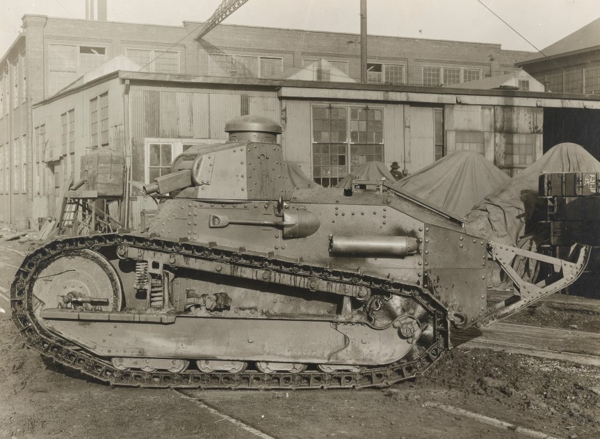
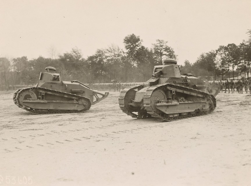
This week’s bonus video features some contemporary footage of a MkVIII Heavy Tank showing off what it can do during a demonstration outside Bridgeport, Connecticut, in October 1918.
This is the last of our series of videos/articles on the US Tanks of WWI, you can find all episodes here.
The MkVIII Heavy Tank holds the distinction of being the result of the first successful international co-operative tank project. Developed with input from British and American designers and engineers, intended to be equipped with British weapons and an American engine, with parts made in the US and Britain and to be assembled in France – a truly international undertaking. The MkVIII, sometimes referred to as ‘The International’ or ‘Liberty Tank’, owed its basic design to earlier British heavy tanks but a number of important changes were made.
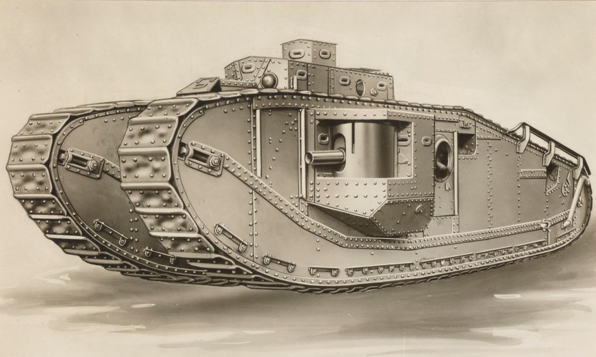
Port side of a MK VIII heavy tank (US National Archives)
Intended for introduction in 1919, the war ended before the MkVIII could enter service and even before its French factory had been completed. It did, however, see some production and inter-war service providing the heavy tank backbone of the US’ tank force for many years.
The design evolved from work by British Lieutenant G.J Rackham with later input from American engineer Major Herbert Alden. The MkVIII heavy was very much an evolution of the earlier British rhomboid heavy tanks but Rackham and Alden made some important improvements. Chiefly the redesigning of the tank’s sponsons which housed a pair of British 6pdr guns. While the tank was a foot narrower than its predecessors, the new folding sponsons could enabled the tank to be transported more easily by rail and to also, in theory, navigate narrow spaces. Alden patented this feature in December 1918 (US #1366550). Additionally, the commander’s ‘outlook turret’ positioned on top of the tank’s turret, which had vision slits on all four sides, was also retractable. Alden’s sponsons were hinged at the front and mounted on rolling bearings so they could pivot inwards.
Alden’s patent for his pivoting sponson (US Patent Office)
The MkVIII directly addressed several shortcomings of earlier British heavy tanks, firstly the engine was insulated in its own compartment to prevent exhaust fumes overwhelming the crew. A new ventilation system was also added with a fan keeping fumes out of the fighting compartment. Secondly, overall visibility was improved with protected vision and revolver slits and the addition of the tank’s commander’s turret.
Another important design change was the move to longer tracks, about 5 inches in length, which required a dozen less links than the MkV. Each of the links was shallowly stamped to increase its strength. In terms of armament the MkVIII was designed as solely ‘male’ – with guns in its sponsons, not machine guns – however, with a raised tower on the tanks roof this provided positions for five machine guns in hemispherical ball mounts. Two more machine guns could be mounted in the tank’s hull doors located behind the sponsons. The ammunition for the 6pdr guns was held in a central ammunition storage box but the sponsons also had shell storage space surrounding the guns themselves.
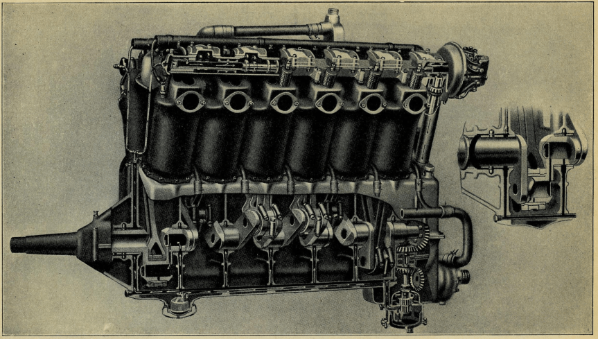
The MkVIII’s V12 engine (US Army Preliminary Handbook for the MkVIII)
The 37 ton tank was to be powered by an American V12 aircraft petrol engine manufactured by the Liberty company. Although a cheaper, water-cooled Liberty was eventually used in the American tanks. The British developed a similar 12 cylinder engine from Ricardo. This, in theory, produced 300 horsepower with a top speed of just over 6mph and a range of just under 40 miles. The MkVIII’s engine was moved from the centre of the tank to a separate engine compartment at the rear of the tank. This not only reduced engine heat and fumes in the fighting compartment but also made communication easier. Some sources also suggest that the MkVIII was the first tank to have an electronic intercom system.
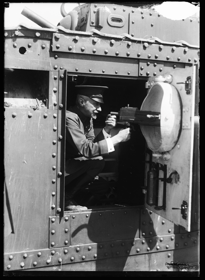
An officer illustrates how one of the tank’s ball mounted machine guns worked – the gun itself is an M1919 tank machine gun (US Library of Congress)
The American Preliminary Handbook for the MkVIII listed the tanks as being equipped with 7 ‘Hotchkiss .303-inch machine guns’, these are likely to be Hotchkiss Portative MkI*s popular in British service. In US service, however, the tanks were likely later equipped with the new Browning M1919 Tank Machine Guns. The tank carried 182 rounds of 6pdr ammunition and an additional 26 smoke rounds as well as 21,000 rounds of machine gun ammunition to keep the 7 machine guns fed.The tank’s armour was also increased lightly from the previous MkV, with 16mm of frontal armour and between 10 and 12mm at the sides. Less vulnerable areas had armour 6mm thick.
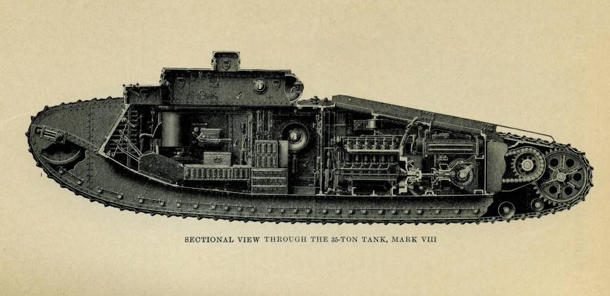
A partial cutaway view of the tank (US Army Preliminary Handbook for the MkVIII)
The American MkVIIIs were initially planned to be manned by an eleven-man crew made up of a driver, commander, two gunners and two loaders to man 6pdrs, four machine gunners and a mechanic. Later crew complements probably dispensed with two of the machine gunners as the US MkVIIIs operated during the inter-war period dispensed with two of the midships machine guns. The British crew was planned to be smaller with 8-men fighting the tank, made up of a driver, commander a pair of gunners and loaders for the main guns and two machine gunners who were tasked with manning the tank’s various machine guns. Impressively the 34 feet long tank also had room for as many as 22 infantry to be transported.
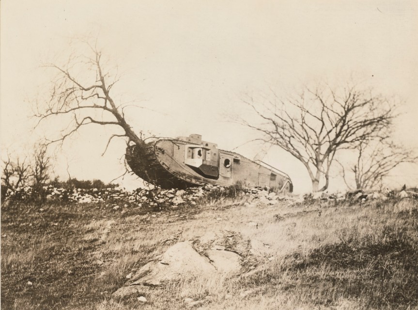
A MkVIII demonstrating its power by destroying a tree during testing (US National Archives)
As an allied collaborative project the production of parts was to be a collaborative effort. Britain was to contribute armour plate, structural frame work and armament. The American contribution was to include the automotive parts including the engine, brakes, drive sprockets, gears and transmission.
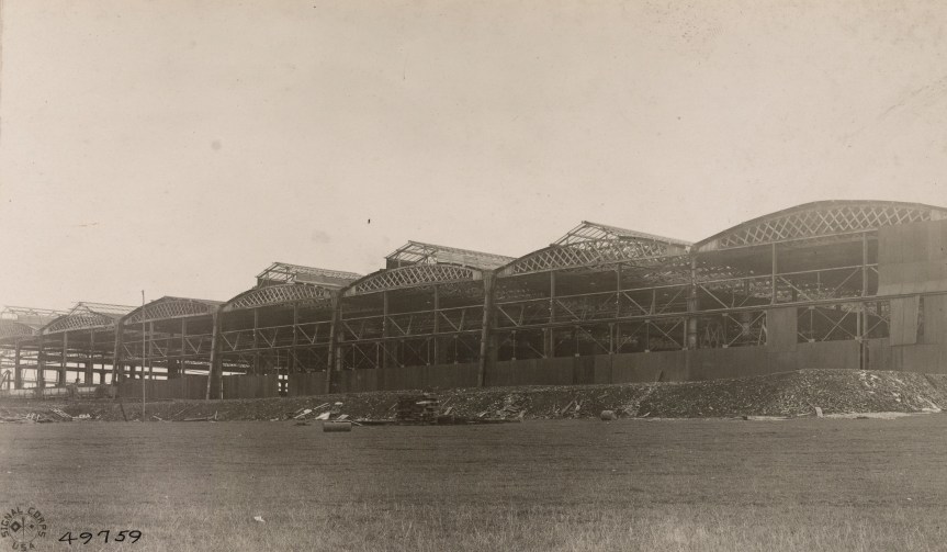
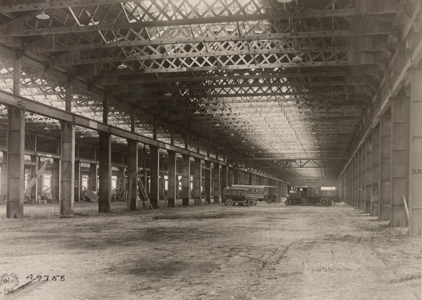
The French were largely uninterested in British heavy tanks and their primary contribution to the MkVIII project was a factory site near the village of Neuvy-Pailloux, 165 miles south of Paris, in central France. Critically located well away from the fighting on a main rail route north, through Issoudun. Construction of the impressive factory appears to have begun in early 1918, with the framework of seven long production halls and the installation of a powerplant and generators and the building of railway sidings completed before the armistice in November 1918. Production barely got underway in Britain, let alone in France. Contemporary photographs taken in January 1919, by the US Army Signal Corps show the factory with its roof in various stages of completion, its shop floors unfinished and empty and open to the elements. The factory would eventually be completed and used by the French army as an artillery park and later a maintenance depot.
The incomplete Neuvy-Pailloux factory c.1919 (US National Archives)
The oringal plan was for the tank parts to be shipped across the channel and the atlantic through France’s western coastal ports to be shipped by rail to Neuvy-Pailloux where they would be assembled into working tanks. It was envisaged that the workforce would be made up of Chinese labourers with British and American foremen and managers.
Inside the incomplete factory (US National Archives)
As many as 3,000 tanks were planned for 1919. The British intended to build 1,450 MkVIIIs of their own use in addition to the 1,550 to be produced for general allied use. The British tank parts were to be manufactured in Manchester, by the various workshops of the Manchester Tanks Association, and in Glasgow, by the North British Locomotive Company. Mass production in Manchester never got underway and the initial British MkVIIIs were built in Glasgow – just 24 are believed to have been built, all but six of these were scrapped almost immediately. The first American tanks were assembled by the Locomobile Company of Bridgeport, Connecticut. The American-assembled MkVIII completed acceptance trials in the spring of 1919. With the end of the war the US order was reduced from 1,500 to 100. 100 sets of hull components were bought from Britain and assembled with corresponding American parts at the Rock Island Arsenal.
A US MkVIII at Camp Meade, c.1921 (US National Archives)
The MkVIII was the last of the British rhomboid heavy tanks. The handful of British MkVIIIs built never entered service but the 100 American tanks along with American built M1917s, MkV Heavies and Renault FTs brought back from France, formed the backbone of the US Tank Corps throughout the early inter-war period. The US MkVIIIs remained in use as training tanks until 1932. Today, just three are believed to survive; two in the US and one in Britain.
With many of us being stuck in COVID-19 imposed lockdowns I thought now would be a good time for a video-walk around Donnington Castle. Think of it as a virtual stroll. The 14th century castle found itself embroiled in a long siege during the English Civil War (1642–1651) with extensive earthworks built to defend the old castle.
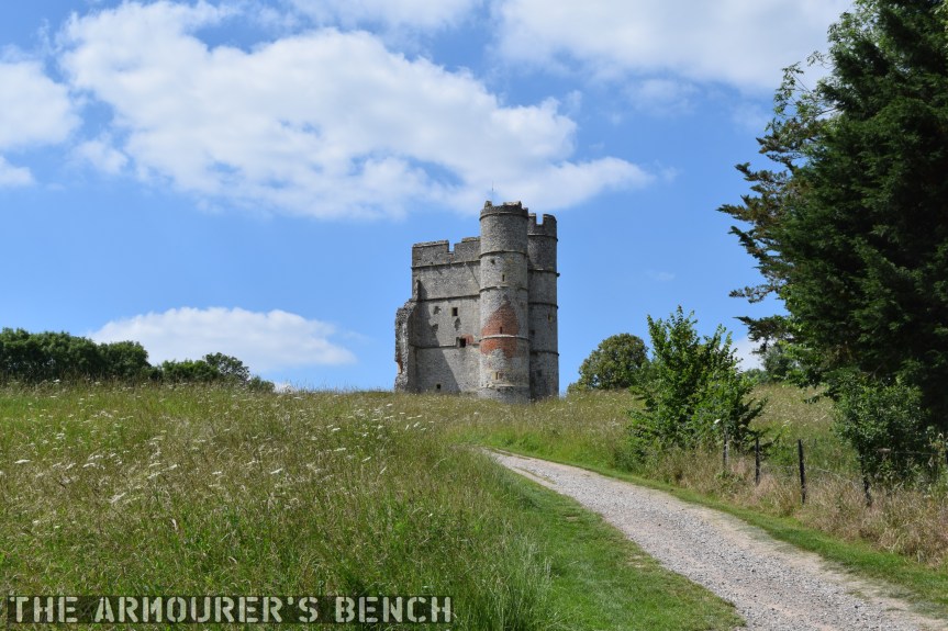
The approach to Donnington Castle (Matthew Moss)
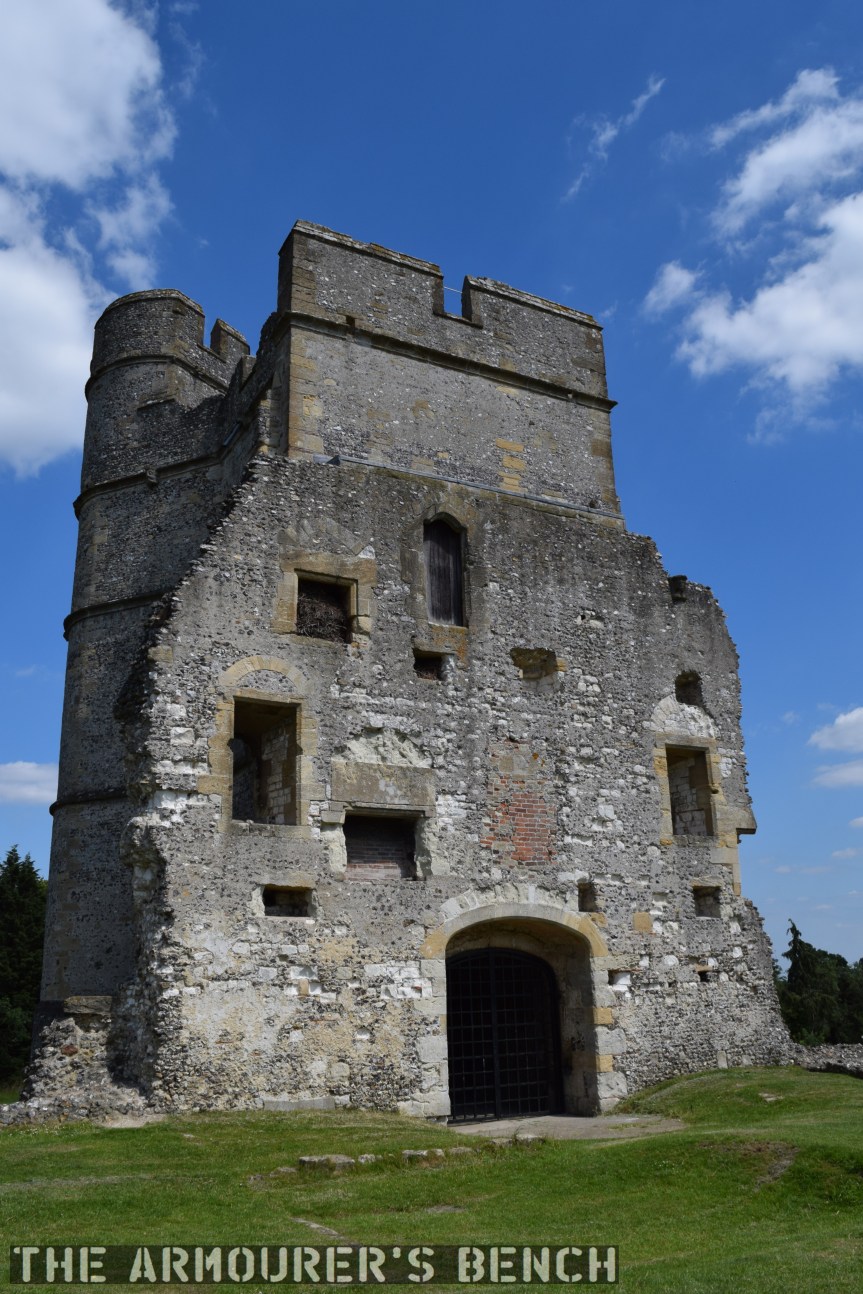
Donnington Castle in Berkshire is sited at the top of a hill overlooking the River Lambourne, a mile north of Newbury. It was built by its original owner, Richard Abberbury the Elder, under a license granted by King Richard II in 1386. The castle was designed as a fortified residence with a rectangular enclosure with a three-storey round tower at each corner and two square towers midway along the longest sides. The gatehouse, the only remaining part of the castle is a three-storey rectangular building with two, four-storey, round towers flanking the entrance. The wall opposite the gatehouse bows outwards.
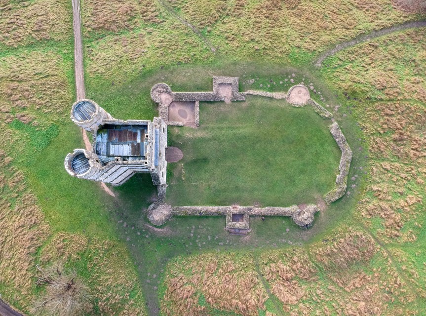
Aerial view showing the outline of the castle’s walls (Matthew Prior)
The castles walls probably enclosed a hall, kitchens, storerooms and accommodation for guests with the main quarters being in the gatehouse keep. While not an elaborate, larger or militarily complex as some other castles it still imposing sight.
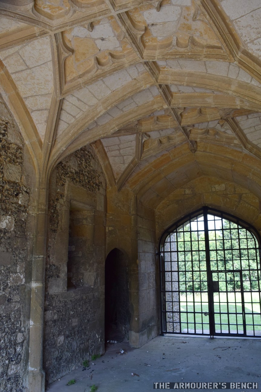
The rear of the gatehouse shows the outline of former rooms which were damaged and demolished. Note the later brick used to repair some damage (Matthew Moss)The vaulted and corniced ceiling inside the gatehouse entrance, hinting at the castle’s role as a home more than a military position (Matthew Moss)
Both Henry VIII and Queen Elizabeth I visited the castle during the Tudor period. The castle didn’t see action until the 1640s and the outbreak of the English Civil Wars (1642-1651). While the castle has been owned by a Parliamentarian family, the Royalists took control of the caste in 1643 and began fortifying it. Sir John Boys set about building elaborate star-fort defences around the original medieval castle. Boys built a set of angular trace Italienne at the considerable cost of around £1,000. Donnington Castle was one of many medieval castles that saw new life during the Civil Wars. Old castles along with churches and country houses were re-purposed and hastily defended by new earthworks.
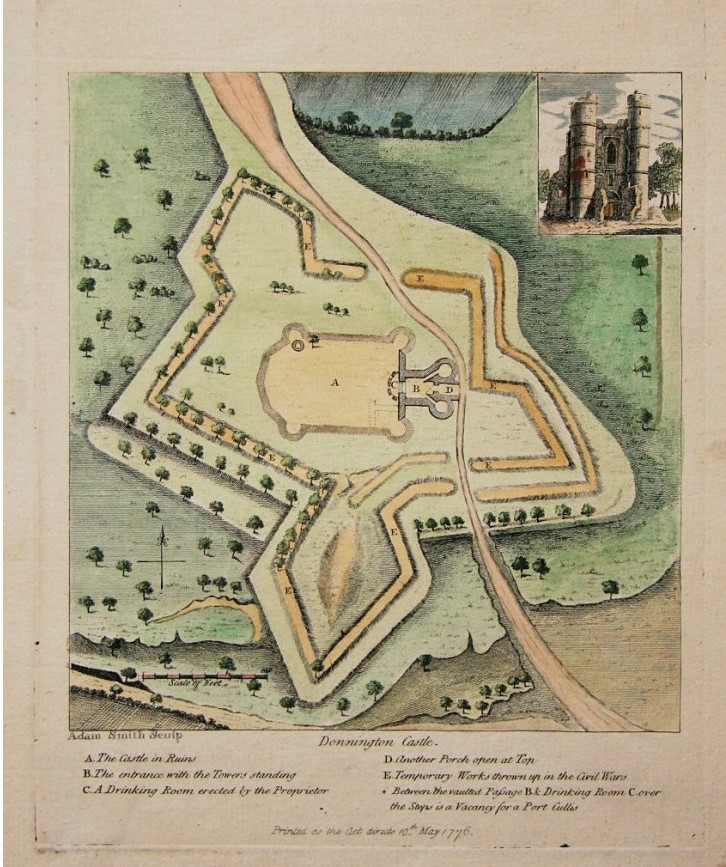
18th Century map showing outline of the castle’s Civil War defences
The castle’s new defences included four new bastions, with emplacements for cannon, ditches and a palisade wall. Royalist forces at the fort initially numbered just over 200 men and four cannon. The Second Battle of Newbury was fought within sight of the castle in October 1644 and after the battle the castle’s defences were reinforced by a number of large guns left behind by King Charles’ retreating forces.
The castle itself was attacked numerous times during the war, during the second attack on the castle part of the wall was damaged. The castle had to be and had to be relieved by Royalist forces twice the final siege in March 1646 began. The castle was badly damaged after the siege with its walls and outer towers hardest hit but remained defensible. With no hope of relief the garrison surrendered and were allowed to march out with their colours.
As with so many other castles after the war Parliament voted to demolish it and only the gatehouse was left standing. It is now a scheduled monument.
In April 1919, a lone US-built M1917 light tank climbed over 11,000 feet up a mountain in Colorado. We are lucky enough to have some original photos and footage of the tank’s climb up Pikes Peak in the Rocky Mountains.
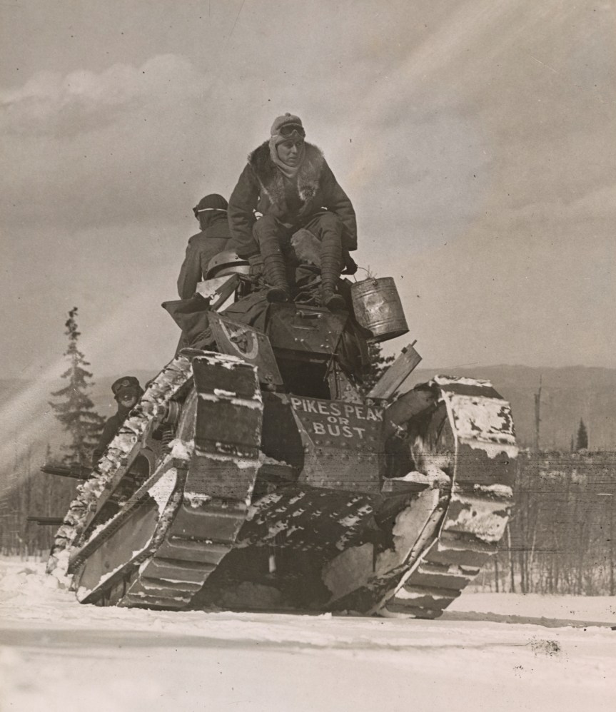
The tank with ‘Pikes Peak or Bust’ painted on its hull (US National Archive)
Why was a tank driving up a mountain?
Simply put the expedition was a publicity stunt to help raise cash to pay off America’s war debt. By 1919 the cost of US involvement in World War One had reached $32 billion – that’s around $547 billion today.
The purpose of the stunt was to encourage Americans to purchase ‘Victory Liberty’ War Bonds which would help pay off some of the debt accrued by the war. This was the fifth, and final, round of Liberty Bond sales. The drive began in mid-April 1919, and aimed to sell $4.5 billion of government bonds.
The tank arrived in Colorado Springs at the beginning of April and on the 14th a crowd of nearly 1,000 people watched Mrs W.H.R. Stote, the chairwoman of Colorado Springs’ Victory Liberty loan committee, christened the tank ‘Little Zeb’ – after explorer Brigadier Zebulon Pike – who led an expedition that attempted to climb the mountain in 1806)
Mrs Stote reportedly declared “I charge you with making the trip to the summit. As the Victory Loan shall not fail, you must make it to the top!” The tank’s commander Sgt. A.H. Worrell, told The Colorado Springs Gazette that he had “driven tanks over trees and trenches on the western front and I am betting we get to the top.”
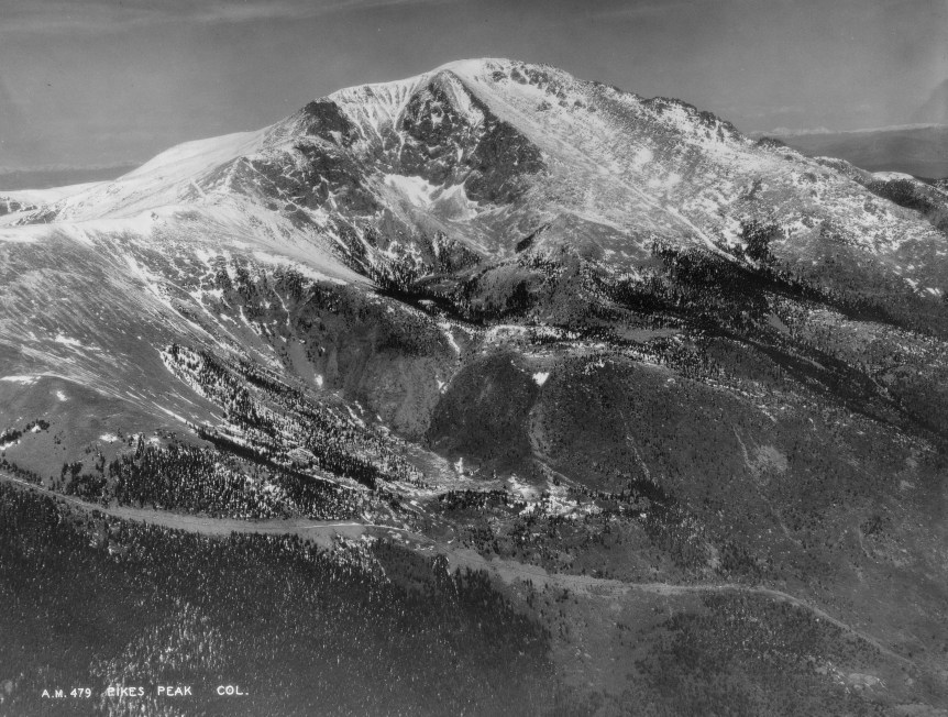
The road up to the summit of Pikes Peak, photographed in 1934 (US National Archive)
At the time the 19 mile road up to Pikes Peak was said to be the ‘World’s Highest Motor Drive’ with the summit at 14,115 feet (or 4,302m). Cpl. Howard Brewer, the tank’s driver told reporters “I know we can climb it. Given time, the tank could go to the top of the world.” In terms of publicity having the tank make it up the mountain would certainly have been quite a feat.
On the front of the tank’s hull the words ‘Pike’s Peak or bust’ were painted in white – this is a reference to a phrase coined by prospector’s during the Pike’s Peak Gold Rush of the 1860s.
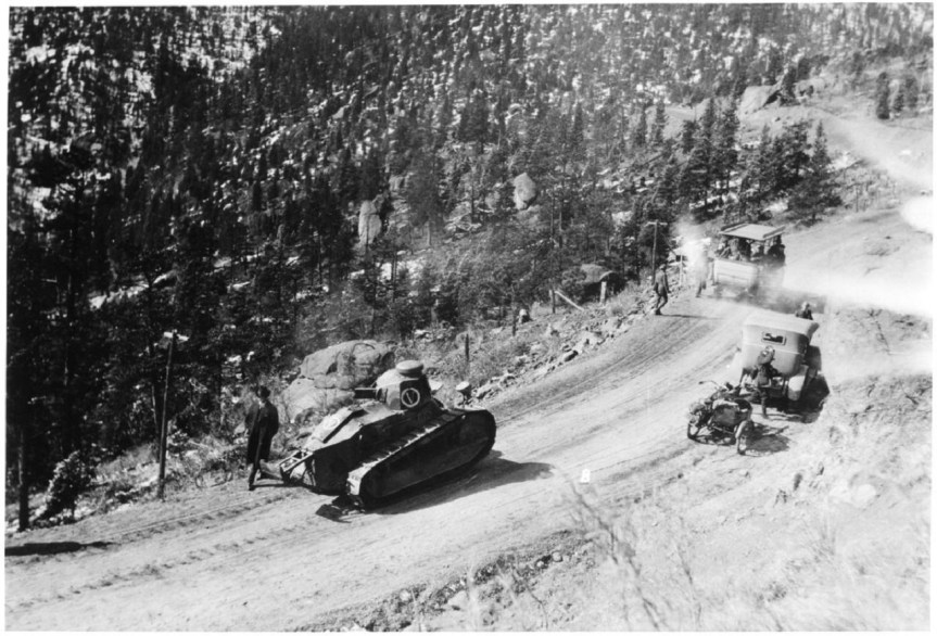
The tank on the road up Pikes Peak (Pikes Peak District Library)
The tank was driven by Corporal Howard Brewer and tended by a crew of mechanics and support vehicles. The road which climbed the mountain was unsurfaced and had only been completed in 1916. The tank’s ascent began on April 15, and incredibly over the next two days the tank climbed to 11,440 feet, 13 miles along the road and through several deep snow drifts, reportedly up to 20-feet tall, before a track plate snapped. After repairs the tank and support convoy pressed on – but the tank never made it to the summit. Not because of mechanical failure but unbelievably because it was needed to appear in other Colorado towns as part of the Victory Loan drive.
While the tank may not have reached the very top of the mountain, it unsurprisingly became a record breaker – setting the first elevation record for tanks. Western Union claimed that it also set a distance record for continuous distance travelled and penetrated the farthest into the snow than any other vehicle had ever done at that time of year – battling snow drifts up to 20 feet tall. While the US-built M1917 was never tested in battle the drive up the mountain proved it was a capable, hardy vehicle – demonstrating the tank’s abilities.
Bibliography:
Various photos and contemporary footage taken from the US National Archives (source)
Additional photos held by the The Manitou Springs Historical Society (source)
‘Army’s Tank Assault on Pikes Peak Was About More Than Being Macho’, The Gazette, M.L. Cavanaugh, (source)
U.S. Economy in World War I, Economic History Association, (source)
The Walther P5 was developed in the mid-1970s as an response to the West German police’s continued search for a 9x19mm service pistol to replace the older smaller calibre pistols then in service, like the Walther PP. It was developed to fit the new police specification for a small, handy pistol which could be brought into action quickly. Walther’s design competed against pistols from Mauser, Heckler & Koch and SIG Sauer.
Walther P38 (Rock Island Auctions)
The P5′s design evolved from the P38, combining the lock work and dual recoil springs of the P38 (re-designated the P1 in 1963) with a shortened barrel and a full length slide. While a shortened P38k had been produced in the early 1970s, this was only an as an interim solution. The P38K retained the same slide and frame as the original P38s, but had the front sight mounted on the front strap of the frame and none of the pistol’s contours were rounded to aid drawing and returning to a holster. Only around 2,600 P38Ks were produced.
Following the attack on the 1972 Munich Olympics games West German police began the search for a new service police. Walther’s response, the P5, was introduced in 1978. The P5 is a locked-breech pistol and has double-action/single-action (DA/SA) trigger. It uses the same short-recoil operated system and locking mech as the P38. This means that the barrel and slide recoil together for a short distance before the locking block falls and allows the slide to continue moving rearward, ejecting a spent case and chambering a new round.
Walther P5 (Matthew Moss)
Walther moved the P5’s decocker from the slide to the frame and this also served as the slide stop and slide release. I would say that the P5’s decocker is easier to operate, with a shorter length of travel, than the SIG P6’s.
Following the West German police specification Walther designed the pistol to be safely and rapidly brought into action, and as a result dispensed the manual safety. Instead, the pistol could be carried in condition two – with a round in the chamber and the hammer down. This was safely achieved by some upgrades to the P5’s hammer and firing pin. There is a small recess in the pistol’s hammer for the firing pin. The firing pin only moves into alignment with the hammer surface when the trigger is pulled.
The P5 has a 3.5 inch (9cm) barrel and fed from an 8-round, single stack, magazine with a heel release. Like the P38 the pistol ejects to the left rather than the right. The P5 has a stronger and more durable fully enclosed slide which is contoured to aid holstering. The pistol has an alloy frame, with full-length slide rails and an enlarged trigger guard for use with gloves.
Diagram showing the P5’s parts and internal layout (Walther)
In addition to the P5, Walther also developed a compact model for plain clothes use which had a slightly shorter barrel (3.1 inches), slide and a truncated hammer. It was introduced in 1988 and had a lighter alloy frame with the P5 Compact weighing 750g (1.65lbs) rather than 795g (1.75lbs). While early production pistols retained the heel magazine release the majority had a thumb release. A small number of P5-Lang, long barrel target pistols were also produced in the late 1980s.
Disassembly is simple and comes directly from the P38. The slide is retracted a little until the barrel catch can be rotated. The slide and barrel can then be slid forward off the frame once the trigger is pulled.
The P5 proved to be an accurate and reliable pistol and once it was accepted by the police trials (along with the designs from Heckler & Koch and SIG-Sauer – the P7 and P6 respectively.) It was adopted by uniformed officers of Baden-Württemberg and Rhineland-Palatinate’s State Police – these pistols were marked ‘BMI’ for Bundesministerium des Innern – the Federal Ministry of the Interior. This pistol is a BMI-marked gun and dates from February 1983.
Walther P5 brochure cover (Walther)
It also became the standard issue sidearm of the Dutch police who purchased around 50,000 pistols, becoming Walther’s largest customer for the P5. The Dutch guns were later fitted with aftermarket Houge rubber grips and some changes to the hammer safety system were later made in the mid-1990s. The Dutch police retired the P5 in 2013 replacing it with the P99Q.
The P5 also saw some military sales with elements of the Portuguese Army adopting it and the P5 Compact was also adopted by the British Army. Selected in the late 1980s for issue as a personal protection side arm. It was designated the Pistol L102A1 and was extensively issued to British troops in Ireland for use while in plain clothes or off duty.
The P5 on screen: Sean Connery as James Bond in, the technically unofficial, 1983 Bond movie Never Say Naver Again. Roger Moore’s Bond also carried it in Octopussy (also in 1983)
While certainly one of Walther’s lesser known pistols the P5 is a well-made, well-designed duty pistol, with comfortable ergonomics – the fiddly magazine catch not withstanding – and the slide and decocker are very smooth to operate. The trigger pull in both the single and double action modes is also pretty good. Overall, around 100,000 pistols were produced before production came to an end in 1993.
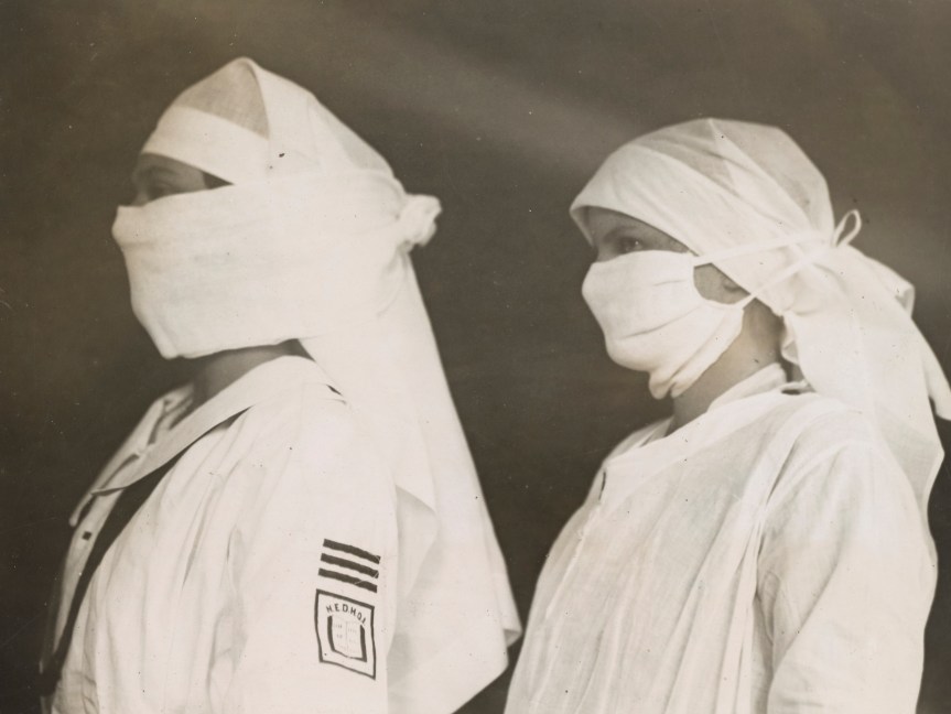
While doing some archival digging I came across this short clip showing Red Cross Nurses in Boston preparing gauze masks to wear while caring for those sick with the Spanish Flu in 1918-19. I was surprised to see the clip end with some advice that remains relevant in the current Coronavirus Outbreak. I thought it was worth sharing as it shows we’ve tackled crisis like these before and come through them – and will again.
Nurses in Boston wearing masks, c.1918 (US National Archives)
The Spanish Flu epidemic of 1918-1920 infected approximately 500 million people and likely killed more people than World War One. To illustrate the impact of the epidemic, in October 1918, the US Army Philadelphia Quartermaster Depot reported that of 1,489 staff were absent with the virus, the report ended “situation not improving”.
A flyer outlining precautions US Naval personnel were to take to avoid contracting influenza or Spanish Flu. The flyer was issued by the US Navy’s senior medical officer, Captain G.L. Angeny, at the Portsmouth Navy Yard in February 1920 (US National Archives)
Continuing our series looking at US tanks of World War One, in which we have already taken a look at the Ford M1918 3-Ton Tank, in this video/article we will take a look at the M1917 Light Tank.
The US Army entered the Great War with no tanks or experience in armoured warfare. When the American Expeditionary Force’s Tank Corps was formed in early 1918, it was equipped with French and British tanks. With plans to rapidly expand the US Tank Corps with battalions training in the US, France and Britain, a large number of tanks would be needed. The corps trained with the French Renault FT light tank and the British MkV but with French production stretched to capacity they could not hope to provide the US with the tanks it was expected to need for operations during 1919.
Renault FT on the Western Front (US National Archives)
As a result the US negotiated with France for a license to produce the FT in the US, commissioned a smaller 3-ton light tank from Ford and entered into an agreement with Britain to build a new heavy tank – the MkVIII. The American-made FTs were designated the Model 1917 6-ton light tank. 4,400 were ordered, with deliveries to begin in April 1918. The Ordnance Department finalised the M1917s design and contracted a number of private companies to build the tanks.
Delays in production, however, meant that the first American tanks were completed in October 1918, and none of the M1917s reached the Western Front before the war ended. As a result, the primary US tank of the war was the original French Renault FT, revolutionary for its turret which could rotate 360-degrees and its rear-mounted engine. It was cheaper to manufacture than the heavier British tanks and could be transported by lorries behind the lines. The FT equipped the 1st Provisional Tank Brigade, what would become the 304th Tank Brigade, commanded by Lt. Colonel George S. Patton. The American FT’s saw action for the in September 1918, at the Battle of St. Mihiel.
US-operated Renault FTs on the Western Front (US National Archives)
144 US FT’s took part in the battle and both the tanks and crews performed well. The Five of Hearts, a 37mm-armed FT with the 344th Tank Battalion took part in the Meuse-Argonne offensive and while making an isolated attack on German positions in support of bogged down US Infantry, the tank was immobilised and its gun mantle jammed by enemy small arms fire. The tank’s commander Sergeant Arthur Snyder recalled:
“My wounded driver kept filling pistol clips and I produced as much fire as possible with our pistols and the crippled 37mm. I paid more attention to the volume of fire than its accuracy for I fear the enemy would close in if the volume diminished. Three machine guns were set up at very close range, but just out of range of our piece with its limited elevation. The fragmentation of our shells did afford some protection but I could not train this fire on the German field piece. The constant hammering of these machine guns at close range was terrific. The hinges on the doors could not stand up under it for long, but it was the mushroom ventilator on top of the turret that gave way. I was hit in the back of my head with fragments of it and bullet splinters.”
Luckily for Snyder the German infantry made no attempt to rush the tank, content to pepper it from a distance, and they quickly retreated when infantry from the 16th Infantry arrived.
In terms of protection Snyder felt that “the armor plate on those old French Renaults was good, but when you came to close quarters the splinters from bullets hitting around the vision slits did considerable damage.” Two of Snyder’s drivers were badly wounded one by bullet splash splinters and the other in the throat.
A newly completed M1917 at the Van Dorn Iron Works, 1919 (US National Archives)
The M1917 was manufactured by the Van Dorn Iron Works, the Maxwell Motor Co., and the C.L. Best Co. Of the original wartime order for over 4,000 tanks, in total just 952 M1917s were produced. 375 of these are believed to have been equipped with 37mm M1916 cannons, while 526 armed with Marlin M1917 tank machine guns. The remaining 50 were outfitted as unarmed signal tanks.
The M1917 has a number of small differences from the FT. Its exhaust is located on left rather than right side of the tank. A new US-designed gun mount and mantlet was used. Solid steel idler wheels at the front of the tank rather than the spoked type used by the French. Additional vision slits for the driver were added and a bulkhead sectioned off the engine from the cab. Like their French cousins the M1917 was manned by a two-man crew, the driver and the commander who also acted as loader and gunner.
Marlin M1917 Tank Machine Gun (US National Archives)
A different, American-made, engine – a water-cooled 4 cylinder engine built by the Buda Engine company was used. Developing 42 horsepower, it had more torque than its French counterpart but was no faster, with a top speed of between just 6 – 8 miles per hour. The tank weighed just over 7 US tons and was 16.5 feet long and 7ft 7” tall. Its armour was 0.25″ to 0.6″ (6.35mm to 15.25mm) thick – slightly thinner than its French counterpart. The majority of the tanks were armed with machine guns, using the .30 calibre M1917 Marlin tank machine gun, rather than the French Hotchkiss. The ‘male’ or cannon armed tanks had a 37mm gun and carried more than 230 shells for the gun. The Marlin was later supplanted by the early iteration of the M1919 Browning tank machine gun. 50 command and signals tanks were also built, these unarmed tanks were similar to the French TSF (télégraphie sans fil) and fitted with a wireless radio.
An M1917 climbing Pikes Peak, April 1919 (US National Archives)
Perhaps the M1917s most impressive feat stemmed from a publicity stunt in April 1919, when a M1917 climbed Pikes Peak, a mountain in Colorado. At the time the road up Pikes Peak was said to be the ‘World’s Highest Motor Drive’, a single tank was driven up the mountain as part of fund raising efforts for the fifth, and final, round of Liberty Bond sales, which hoped to raise $4.5 billion from the sale of government bonds. We’ll have a separate looking at this exploit at a later date!
None of the M1917s reached the frontline but many were used a props for selling war bonds – in this photo dated April 1918, a platoon of M1917s is seen after they arrived at Camp Meritt by train, they are about to be painted up in camouflage for a Victory Loan parade in New York.
US M1917s exercising with infantry, at Camp Meade, 1920 (US National Archives)
After the war the M1917, along with just over 200 French-made FTs brought back from France, formed the backbone of the US Tank Corps. In these photos we can see several tanks taking part in a mock-battle with supporting infantry at Camp Meade in May 1919. This photo show men learning to service their vehicles at Camp Meade, in December 1919.
Obsolete M1917s arriving in Canada in 1941 (Library & Archives Canada)
But by 1921, the Corps had lost its independence and been all but disbanded with the Infantry given control of America’s tank force. A handful of the M1917s were deployed briefly overseas with the USMC, during the 1920s, but the M1917 was resigned to training as it became increasingly obsolete. They were finally removed from service in the mid-1930s. When World War Two broke out the remaining M1917s were sold to Canada and were reportedly used to help train the Royal Canadian Armoured Corps before many of them were finally scrapped.
Footage courtesy of the US National Archives (source)
Camp Colt to Desert Storm: The History of U.S. Armored Forces, G.F. Hofmann & D.A. Starry (1999) Tanks: 100 Years of Evolution, R. Ogorkiewicz (2015)
Light Tank M1917, Tank Encylopedia, C. Moore, (source)
The Saga of the Five of Hearts, Armor, July-Aug. 1988, Maj. Gen. W.R. Kraft Jr. (source)
In the late 1950s the US military began development of a bomb capable of destroying deeply buried bunkers. The result was a bunker busting unguided thermonuclear bomb. Durng a visit to the Atomic Testing Museum, in Las Vegas, Matt had the chance to take a look at a decommissioned B53 up close.
B53 on display at the Atomic Testing Museum (Matthew Moss)
The B53 is a two-stage high-yield thermonuclear weapon, designed as a bunker buster, that could deliver a massive shockwave deep underground to the deepest Soviet command and control bunkers. Developed between 1958 and 1961, the B53 was intended to combat deeply emplaced Soviet bunkers with a yield of 9 megatons. It used a highly enriched uranium core as its primary fission stage with Lithium-6 deuteride as its second stage fusion element. The warhead itself was developed from the earlier Mk46 warhead, the experimental TX-53 was tested at the Pacific Proving Grounds as part of Operation HARDTACK I, which saw no less than 35 nuclear test detonations. Codenamed HARDTAK OAK, the TX-53 was detonated aboard a floating barge on 28th June 1958, with a yield of 8.9 megatons. The detonation created a cloud 78,000 feet (23.8 km) tall.
Cloud produced by HARDTACK OAK (Los Alamos National Laboratory Archive)
Designed to be dropped from the Strategic Air Command’s B-47, B-52 or B-58 bombers, the B53 is a gravity bomb which free fell to its target and could be air or surface detonated. The bomb itself weighed 8850 lbs or 4014kg and the casing is 12.5 feet long (3.8m) and just about 50in (1.27m) in diameter. The bomb’s outer-casing is split into a nose section, a two-piece central casing and the rear assembly with four fins which housed the parachute assembly. They were built by the Atomic Energy Commission between 1962 and 1965, over 340 bombs were built. Initially designated the Mk53 it was re-designated the B53 in 1968, when the US Air Force updated its ordnance nomenclature.
The bomb itself could be deployed in four ways: a delayed surface burst, a free fall air burst, a parachute retarded air burst (the B53 had five parachutes at the rear which can be deployed) or an immediate contact surface burst. Here we can see the panel to control the parachute deployment, with markings for safe, free fall and retard.
Declassified general diagram showing the assemblies of the B53 (US DoD)
The B53 was obsolete in terms of its safety by the early 1980s with none of the more modern safety features such as an Enhanced Nuclear Detonation Safety (ENDS) additionally its explosive lens, consisting of a mix of RDX and TNT was not an insensitive munition – meaning it wasn’t designed to resist detonation from external stimuli or damage. The B53 also had no Fire-Resistant Pit (which prevents the spread of radioactive material in the event of a far), Permissive Action Link (which prevent unauthorised arming) or Command Disable safety measures.
B53 at the Pantex Plant in Texas about to begin the dismantling process (National Nuclear Security Administration)
Many of the B53s in US inventory were decommissioned in the mid-1980s, and by 1987 just 50 were retained in inventory. The last of these were disassembled and decommissioned by October 2011 – after being in service for 50 years. The B53 was replaced in its bunker busting role by the smaller B61 Mod 11.
Matt recently visited Berlin and took the opportunity to visit the German-Russian Museum in Karlshorst, the site of Nazi Germany’s unconditional surrender. The museum’s centrepiece is the hall in which the surrender documents were signed, restored to how it appeared at that historic moment.
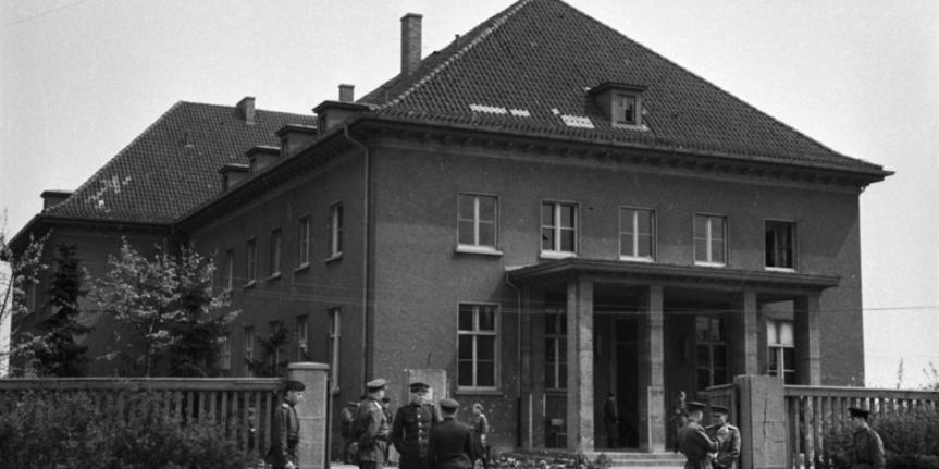
The hall itself is inside what used to be the officers’ mess of the Wehrmacht’s pioneer corps training school No.1 (Pionierschule 1) which was established in 1936 in Karlshorst, an eastern suburb of Berlin. The officers’ mess building was built in the late 1930s. Later, in 1942 the school was renamed the Fortress Pioneer School (or Festungspionierschule).
The Pioneer School’s Officers’ Mess under Soviet occupation, c.1945
During the Battle for Berlin and the Soviet push into the centre of the German capital, the school was occupied by a Soviet battalion on 23rd April. The Soviet military maintained a presence at the former pioneer school for the next 40 years, with parts used by the KGB.
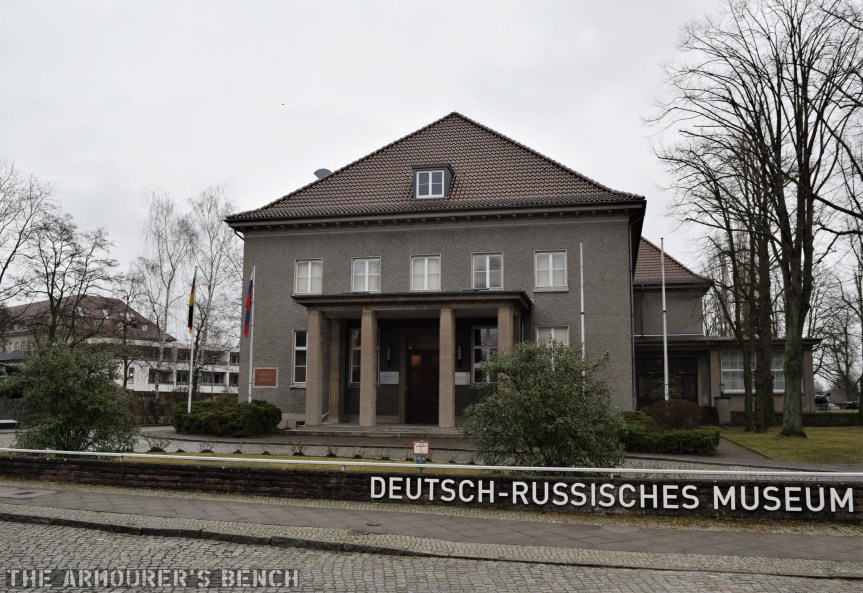
After the war the building housed the Soviet Military Administration in Germany until 1949, when the German Democratic Republic was formed. Today, much of the school has been reclaimed for housing and the mess the building is home to the awkwardly named, German-Russian Museum which tells the story of WWII from the Russian perspective.
The former Officers’ Mess today (Matthew Moss)
The surrender was signed by three representatives of the German high command, Field Marshall Wilhelm Keitel, Admiral Von Friedeburg and Colonel General Stumpff early on the 9th May, 1945 – in the presence of Soviet commander in chief Marshal Georgy Zhukov and Air Chief Marshal Arthur Tedder – Deputy Supreme Commander at Supreme Headquarters Allied Expeditionary Force.
The hall in which the surrender was signed (Matthew Moss)
The initial instrument of surrender had been signed in Riems, in France, the day before but the documents were officially ratified in Berlin at 00:16, on 9th May. The Soviets believed it was more fitting that the surrender be signed in the German capital – highlighting the Soviet role in victory. The surrender ended both the last of the fighting around Berlin as well as the war in Europe.
In 1967 the Soviet Armed Forces in Berlin established the museum, then called the ‘Museum of Unconditional Surrender of Fascist Germany in the Great Patriotic War 1941-1945’, the hall was restored to look as it did on the night of the surrender.
It was a surreal experience being in a room which was witness to one of history’s most defining moment and you could certainly feel the history of the room.
The SAR-80’s story begins in the early 1970s, when Frank Waters, the Sterling Armaments Company’s chief designer, began developing a 5.56x45mm rifle for sale to foreign militaries. While two initial prototypes were produced the project lapsed when Sterling secured a license to manufacture Eugene Stoner’s AR-18.
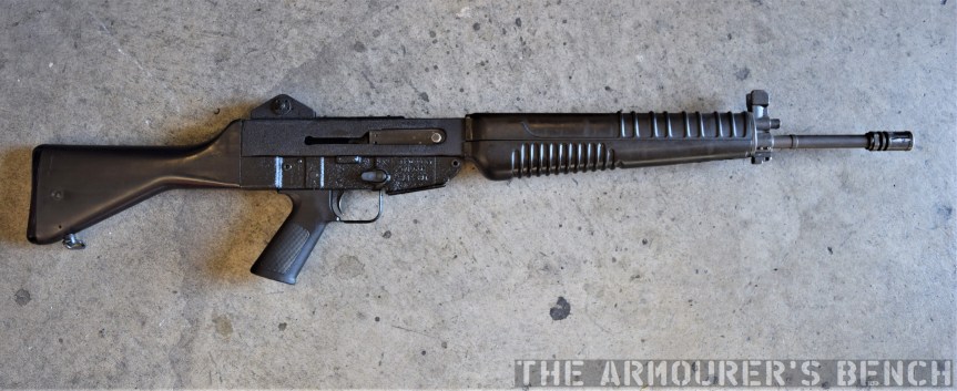
Right-profile view of the SAR 80 (Matthew Moss)
In the late 70s the project was resurrected and in February 1977, two prototypes were sent to Chartered Industries of Singapore (CIS)[later known as ST Kinetics] who had been seeking a 5.56x45mm rifle design to produce for export to sustain production at their factory. The initial prototypes reportedly suffered issues with obturation with some cartridges and Sterling engineers worked to rectify this with another batch of half a dozen prototypes being sent to CIS in late 1977. CIS produced their first pre-production prototypes in 1978, for testing by the Singapore Army. CIS opted for a plastic buttstock and redesigned the handguards too.
Factory brochure photo of Singaporean soldier with SAR 80 (CIS)
Initially described as the Sterling Light Automatic Rifle and later the Sterling Combat Rifle the rifle, however, as it finally entered production in 1979, it became known as the Singapore Assault Rifle 80 or the SAR-80. Some of the earlier rifles are also marked ‘Sterling Assault Rifle’.
The first SAR-80s were delivered to the Singapore Armed Forces in early 1981 for troop trials. Faults with these early production rifles included poor fit and finish and extractors which bent leading to extraction and ejection issues. Refinements made rectified these faults and subsequent production runs had improved reliability.
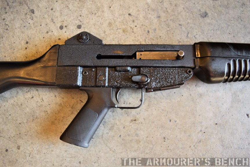
Close up of the receiver, note the sliding dust cover is missing from this rifle (Matthew Moss)
The SAR-80 can be described as a clone of the Armalite AR-18 with their internal designs almost identical. The SAR-80 is gas-operated, with a short-stroke gas piston and a rotating bolt. The bolt has 7 locking lugs, the internal mechanics of the rifle are more or less identical to that of the AR-18, using dual recoil springs and a rectangular bolt carrier. The bolt geometries differ slightly to the AR-18’s and the SAR-80 also has an additional weight inside its bolt – which adds mass and helps slow the rate of fire down to around 600rpm. Like the AR-18 its charging handle is attached directly to the bolt carrier and is reciprocating.
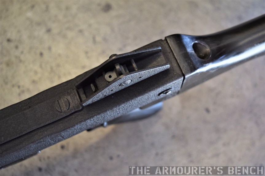
The rifle feeds from standard STANAG magazines and is select-fire, with a selector on the left side of the rifle and a magazine release on the right. The selector layout is modelled after the M16’s and the front handguard’s design was also influenced by the M16. The SAR-80 has simple stamped receiver, similar in profile to the AR-18’s, it has a crackle-paint finish, like that seen on the commercial Sterling Mk4 SMGs. It has a two-position folding rear peep sight and is 97cm (38in) long and weighs 3.7 kg (8.2 lb) unloaded.
Close up of the rifle’s sights, note the rudimentary scope mounting rail (Matthew Moss)
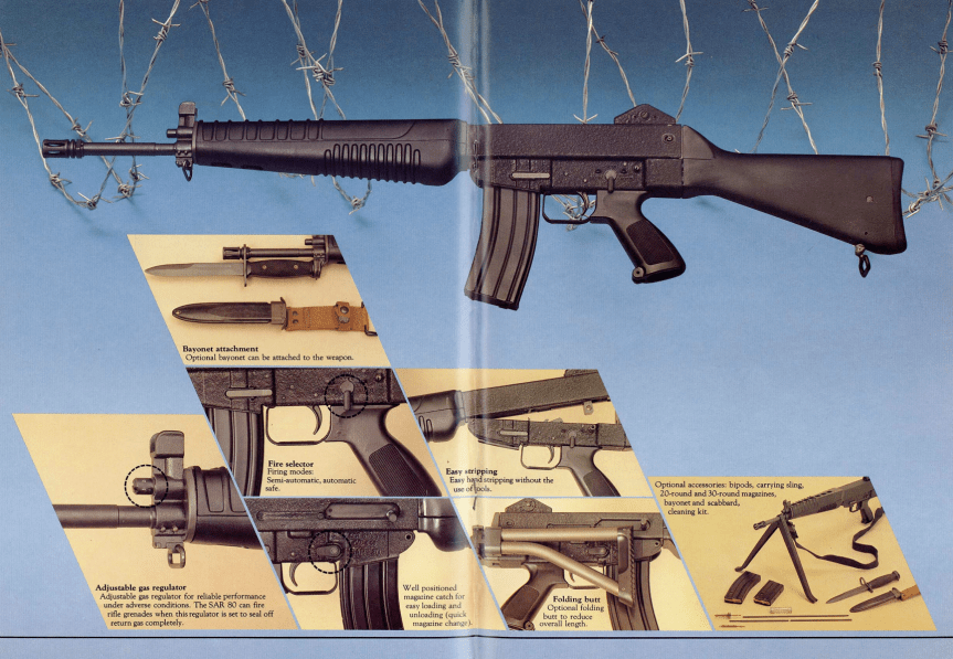
The SAR-80 had a bayonet lug just beneath its adjustable gas block and mounted an M16-pattern bayonet, other accessories included a scope mount, bipod and a blank-firing adaptor. And of course a folding stock variant was also available.
Graphic showing the rifle’s features from factory brochure (Matthew Moss)
I didn’t have a chance to strip the rifle but here you can see the hammer inside the receiver – its worth noting that this rifle does not have the sliding dust cover seen on other examples, and the charging handle slot is completely open.
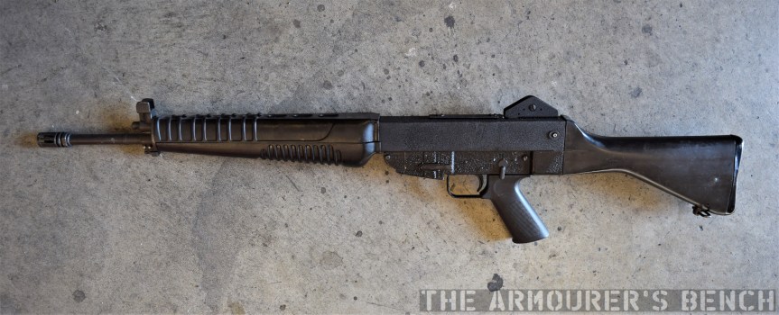
Left-profile view of the SAR 80 (Matthew Moss)
Developed with cost in mind, contemporary literature from CIS state an export price of around $300 per rifle, the equivalent to day of about $930. CIS produced more than 80,000 between 1980 and 1988, it saw limited service with Singapore’s military but did enjoy some export sales, with the SAR-80 used by the Central African Republic’s Gendarmerie, the Croatian Army, the Papua New Guinea Defence Force and the Slovenian Territorial Army. CIS replaced the SAR-80 with the SR-88, a rifle co-developed with Sterling as the SAR-87, but this proved unsuccessful and has since been superseded by the SAR-21 bullpup.