Last month while Matt was visiting the Cody Firearms Museum for their Arsenals of History Symposium he had the pleasure of meeting lots of great people from the historic firearms world. One person he met was none other than Ian of Forgotten Weapons.
Ian was kind enough to suggest doing an interview to share and highlight our work here at TAB with his subscribers. Matt discussed the idea behind TAB and some of the things that we cover.
We very much appreciate Ian’s support of our project and opportunity to chat on camera about our work. Thanks Ian!
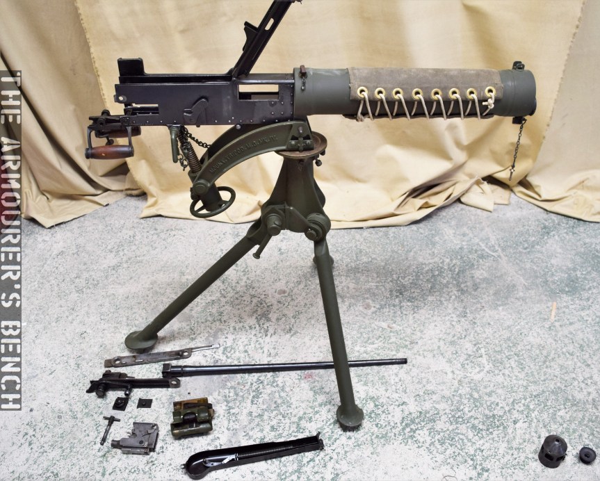
The Vickers Gun is an iconic weapon, developed from the Maxim and adopted by the British in 1912. It served for over 50 years in conflicts all around the world. In this video, we’re lucky enough to have Richard Fisher of the Vickers Machine Gun Collection and Research Association shows us how to disassemble a the gun and talk us through its internals.
Big thank you to Rich for taking the time to help with this video and provide the voice over explaining the process! We’ll have more videos on the Vickers Gun in the future! Check out Richard’s work over on the Vickers Machine Gun Collection and Research Association’s site here.
I’ll let Rich explain the disassembly process in real time in the video but here are a couple of photographs of the gun disassembled:
The Vickers gun field stripped (Matthew Moss)
This is the gun in its fully field stripped condition, with lock still assembled, but with its fusee spring and cover off and its barrel and action removed. Just below the barrel is the feed block.
Here’s the Vickers Gun’s lock disassembled into its 14 component parts:
The gun’s disassembled lock (Matthew Moss)
This photo gives us a good look inside the receiver with the barrel, action and side plates removed, The spade grip assembly simply folds down to allow the action and barrel to be slide out of the gun.
Once the action and barrel is removed you can look straight through the receiver and down through the water jacket (Matthew Moss)
Finally, here’s the gun reassembled and ready for action.
The gun fully reassembled (Matthew Moss)
Thanks again to Richard for his help with this video, it was great to collaborate and hopefully we’ll have more videos with Rich in the future. Please check out the Vickers Machine Gun Collection & Research Association’s site to find out more about what they do. They have some wonderful resources, including a comprehensive collection of manuals, for not just the Vickers but also the wider British Army from the past 100 years. You can also order copies of the brilliant instructional posters which were featured in the video over on the the associations website too!
What’s interesting about the concept of an Obrez or cut-down SMLE is the myth that has grown up around them. They’re often described as being used by men during trench raids or by tunnellers digging beneath No-Man’s Land. But it’s very difficult to confirm the use of cut-down rifles by tunnellers or trench raiding parties.
Right-side view of the rifle (Matthew Moss)
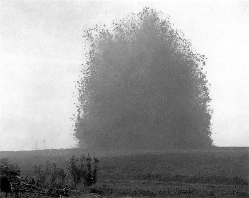
British tunnelling operations began in 1915, as an attempt to break the stalemate on the Western Front, with the formation of the tunnelling companies of the Royal Engineers. Tunnelling had historically been a feature of siege warfare since the medieval period and the Western Front proved no different. Occasionally, opposing tunnels may meet or a counter tunnel might break through often resulting in a short, sharp fight followed inevitably by one side blowing the other’s tunnel up. The final aim of the tunnelling was to lay massive explosive charges beneath enemy strong-points, no fewer than 19 were detonated on the 1st July 1916, the first day of the Battle of the Somme.
The mine under German front line positions at Hawthorn Redoubt is fired 10 minutes before the assault at Beaumont Hamel, on the first day of the Battle of the Somme, 1 July 1916. 45,000 pounds of ammonal exploded and the mine caused a crater 130 feet across by 58 feet deep (IWM)
Of course cutting down serviceable rifles was strictly prohibited and patrols were mostly issued with revolvers, grenades and knives or clubs. For tunnellers who encountered the enemy deep underground they were also normally armed with revolvers, knives and their mining tools.
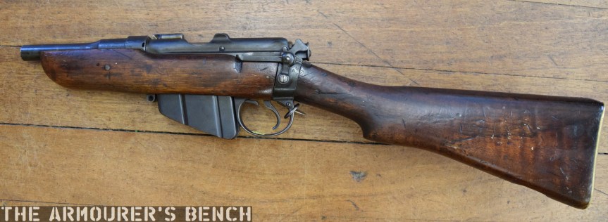
Left-side view of the rifle, note that the rear volley sight remains (Matthew Moss)
The only contemporary reference of using cut-down SMLEs, that I was able to find, comes from a sketch drawn by a tunnelling officer, Major R.S.G. Stokes, who sketched a cut-down SMLE supposedly used by Canadian tunnellers near Ypres. The rifle Stokes drew had a completely exposed barrel and an added front sight post.
The rifle we’re examining differs from the truly Obrez SMLE’s we might normally imagine. The provenance and origins of this rifle are unknown but with its stock still intact it differs from others and actually, in my opinion at least, makes the rifle more user friendly. With the extra point of contact from the butt you can work the bolt faster and don’t have to lower the rifle to work the action. While the SMLE was already one of WW1’s shortest service rifles. This cut-down SMLE is about 64cm or 25 inches long, with a 4 inch barrel.
From descriptions of these subterranean fights they were short, vicious affairs which began with both sides blazing away at one another with pistols before fighting hand to hand.
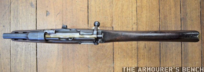
Top view of the cut-down rifle (Matthew Moss)
Most accounts describe revolvers and pistols being the primary weapon used. Captain Basil Sawers, of the 177th Tunnelling Company, described using “little automatics which were meant to shoot where your finger pointed.” Captain Matthew Roach of the 255th Tunnelling Company personally carried two revolvers. Another account from Captain William Grant Grieve describes British tunnellers breaking into a German tunnel, “they encountered a party of Germans and immediately opened fire on them with pistols.”
From the contemporary accounts we have available it appears that immediate volume of fire was key in tunnel fights. For this double-action revolvers and small pistols like those described by Captain Sawers would have been ideal. A cut-down rifle would have been deafening and the muzzle flash would have been blinding in the confines of the tunnel.
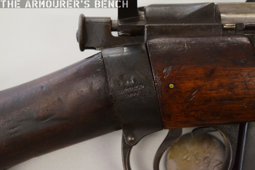
Close up of the cut-down rifle’s wrist socket markings (Matthew Moss)
This rifle has no sights, which while not a problem for short distances in the confines of a trench or a tunnel, anything over 25 yards is going to be challenging. Interestingly, however, who ever cut the rifle down left the long range volley peep sight in place. The rifle itself is a SMLE MkI, originally built in 1906, and as such does not have a charger bridge, which was introduced later with the MkIII, instead it has a pair of charger guides.
Despite cut-down rifles not being officially sanctioned, it is very likely that at least a small number were made – perhaps from damaged rifles which had been salvaged. How many were adapted we will probably never know.
British 2in Trench Mortar, with SMLE ignitor (Matthew Moss)
There were of course a number of occasions when cutting down a rifle was permissible such as the use of cut-down SMLE’s as ignitors for various trench mortars like the 2in Trench mortar that we have covered previously. These ignitors are sometimes confused with unofficial cut-down rifles but the metal grip plates and threaded muzzles are the easiest way to spot them. Some SMLEs were also later adapted as smoke dischargers, one was famously used as a prop in Star Wars: A New Hope, appearing as a Jawa blaster.
We’ve looked at a few cutaways in the past, today we’re going to take a look at a Lee-Enfield Rifle No.4 cutaway.
One of the main drawbacks of the venerable SMLE was that it was expensive and time consuming to manufacture. The No.4 was an attempt to address this. It evolved from the experimental No.1 MkV and MkVI which were trialled in the early 1920s. The key mechanical change was that the barrel was free-floated and had a heavier profile to deal with expansion of the stock. The No.4 also had a new rear aperture sight mounted further back on the receiver giving a better sight picture and a longer sight radius.
Close up of the Rifle No.4 Instructional Cutaway’s receiver (Matthew Moss)(Matthew Moss)
With this cutaway we get a look inside the butt trap, which has a pull-through and oil bottle inside, then as we move to the action we get a look at the rifle’s trigger, sear, sear spring and magazine catch. If we look closely we can see the bolt head catch. The magazine has also been cutaway, with the magazine follower spring just visible.
This cutaway rifle has had all of the wood around its receiver removed, so we can see the magazine housing floor plate and the point where the retaining screw attaches to the trunnion. As we move along we get a look inside the chamber where the outline of the cartridge neck is easy to see and we can also see the barrel’s rifling too.
Rifle No.4 Instructional Cutaway (Matthew Moss)
Down near the muzzle the rifle’s upper retaining band and the hand guard have been cutaway to show the barrel inside. The No.4 was adopted for service officially in November 1939 and just over 4 million were made during WW2. We’ll have a full, more in-depth video on the No.4 in the future.
Check out our earlier videos featuring cutaways including the Pattern 14 and the CETME AMELI.
The footage featured in the video above was filmed at the 1923 US Army Ordnance Exhibition of Ordnance, where John Walter Christie demonstrated his latest amphibious vehicle.
Christie’s amphibious vehicle is one of the earliest. It follows the amphibious variant of the British Mark IX tank, essentially an amphibious armoured personnel carrier (armed only two machine guns) and preceded by the Vickers-Carden-Loyd Light Amphibious Tank in the early 1930s.
Christie’s amphibious gun carrier returns to the land (US National Archives)
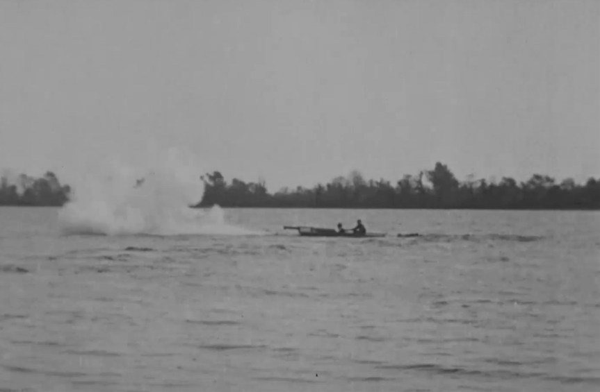
More of a gun carrier than a tank, as the vehicle was open topped, it was, however, equipped with a 75mm field gun. During the footage it not only seamlessly operates on both land and water, it also fires four rounds as it crosses a body of water at the Aberdeen Proving Ground.
Very little is known about the vehicle but it is believed to be the second of three amphibious vehicles developed by Christie during the 1920s. None of the vehicles were purchased by the US military and no major international orders were made either.
Christie’s amphibious gun carrier opens fire with its gun as it travels across a body of water (US National Archives)
The vehicle itself is manned by two people during the demonstration, presumably one steering while the other mans the gun. It appears to have narrow tracks over its four sets of wheels and a pair of propellers at the rear.
Bibliography:
Demonstration of Ordnance Materiel at Aberdeen Proving Grounds, 1920-1926, US National Archives, (source)
This week TAB hit 4,000 subscribers! Thanks for all your support over the last couple of years. I filmed this update on Tuesday during a recent research trip in the south of England. I visited Fort Nelson near Portsmouth and thought I’d film a quick update while I stopped for a break.
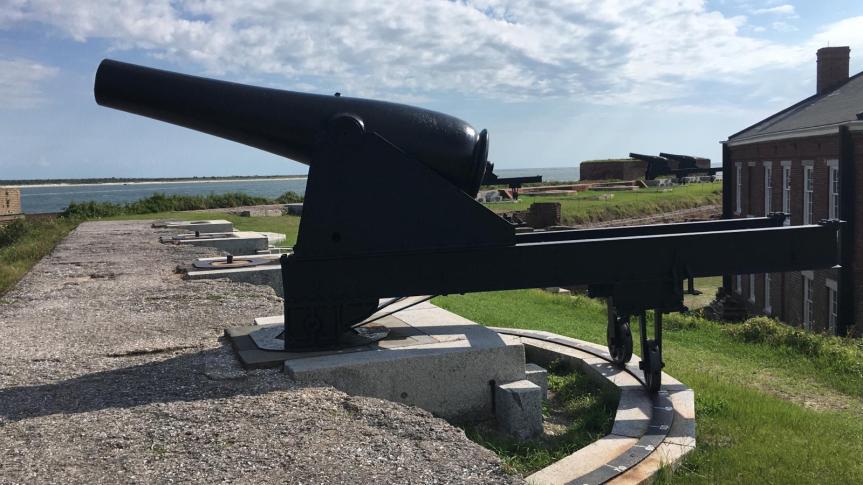
Today, we have a short video looking at Fort Clinch, a fort built at the mouth of the St Mary’s river in North eastern Florida. The pentagonal masonry fort defends the strategic position on Amelia Island, at the mouth of the river and Cumberland sound.
Fort Clinch (Steve Moss)
While the site had been fortified by the Spanish in the 1730s, construction of the present fort began in 1847 after the end of the Second Seminole War. Built as part of the Third System of coastal defences, which began in the 1820s and was characterised by building thick masonry walls. Clinch is one of the smaller forts that were built to defend less important harbours. Named after General Duncan Lamont Clinch, the fort wasn’t fully completed until 1869.
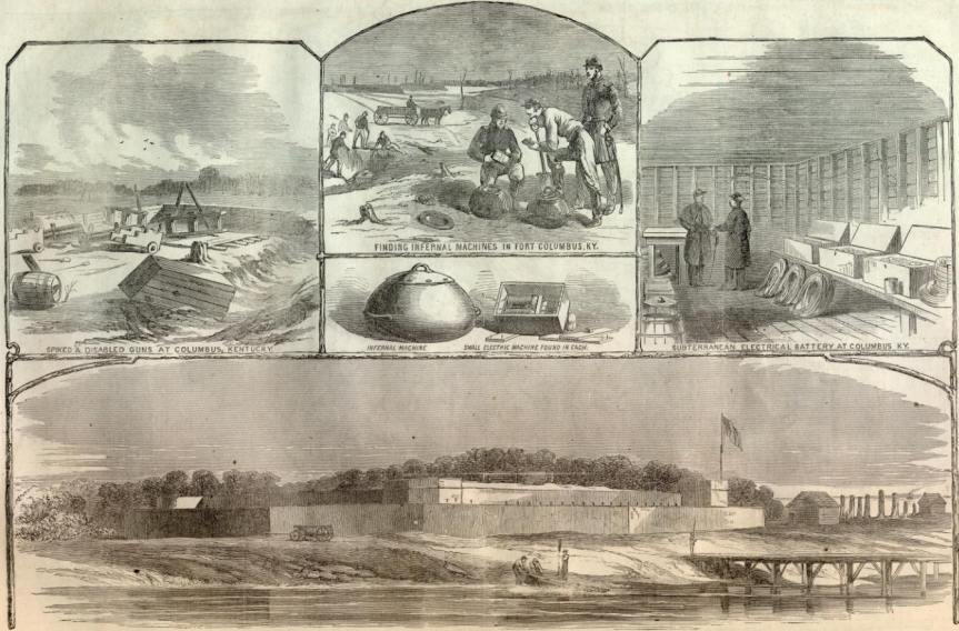
During the civil war it was originally held by the Confederacy before they abandoned it and it was taken over by the Union in spring 1862. The Union then set about finishing the fort. While some sources suggest it was designed to mount as many as 70 guns, it was never fully equipped but we can see that it has mounts and barbettes for around 40 guns on its ramparts.
An illustration of the incomplete Fort Clinch featured in a March 1862 copy of Harper’s Weekly
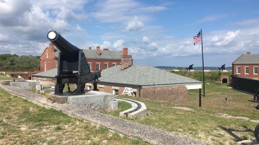
Today, the fort has a handful of Rodman guns in place. The guns appear to be mounted on front-pintle barbette carriages. Beneath the guns are ammunition casements; powder rooms and shot stores, the holes for bringing up ammunition can still be seen.
Rodman guns were a staple of US coastal forts during the late 19th century, designed by Thomas Jackson Rodman, they were hollow cast and much stronger than earlier, traditionally cast guns. They were produced in a variety of calibres ranging from small 8 and 10in guns to huge 15 and even 20in guns. They were designed to be fired from behind a parapet, giving the crew some protection, the parapet at Fort Clinch is missing. The guns themselves were smoothbore and were designed to fire round shot and explosive shell. They would have been manned by an 8-man crew and, depending on calibre, had a range of over 4,000 yards.
An 8 or 10 inch Rodman Gun (Steve Moss)
In 1864, Major-General John Foster, a veteran of the Siege of Fort Sumter, reported that the fort was poorly sited and its design was flawed. It’s clear to see that the fort’s brick walls certainly wouldn’t have withstood fire from rifled artillery for long.
The fort never saw action and once finished wasn’t garrisoned again until 1898 during the Spanish-American War, when a 8″ Rifled Cannon Emplacement with a concrete gun shield was built. The fort was subsequently abandoned again and began to deteriorate until the 1930s when it became part of a state park and was renovated by the Civilian Conservation Corps.
Bibliography:
September 3, 1864: Foster relates the “main defects” of Fort Clinch, Florida, To the Sound of the Guns, (source)
Map of the Entrance to Cumberland Sound Ga. & Fl., Tampa Bay History Centre, (source)
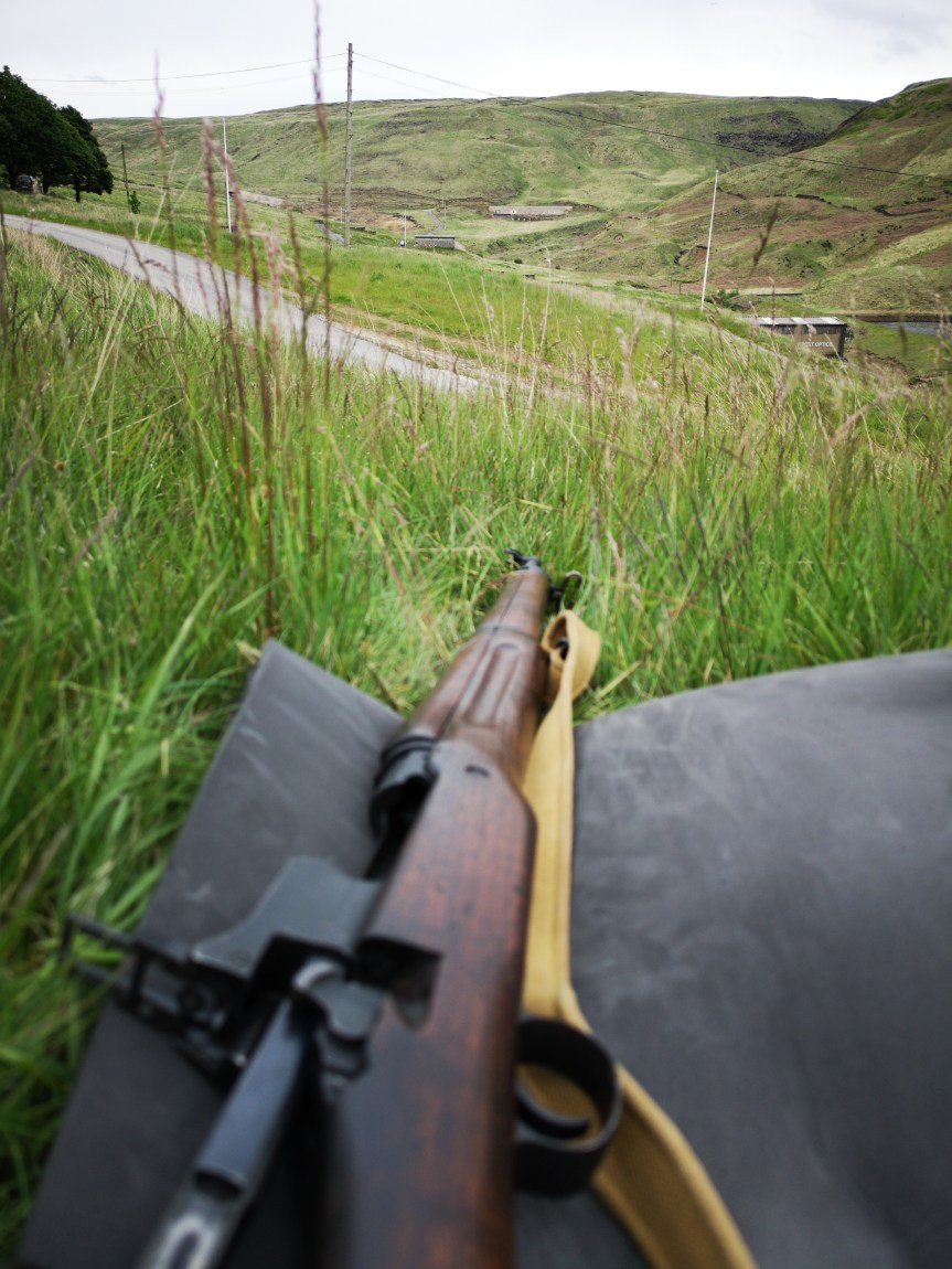
A month ago I posted a short video from a range trip shooting the Remington M1917 at about 100m, getting a feel for the rifle and checking zero. I said in that video that I was planning on stretching the M1917s legs in the near future and last week I got the chance. I had the opportunity to shoot the rifle out to 700 yards (640m) which was a lot of fun.
The view down range from the firing point (Matthew Moss)
With some 147gr S&B I managed a half decent score only missing twice out of 20 rounds. I’ve never shot out to 700 yards especially not with iron sights so it was a fun challenge, amazingly my last round was a bull, which was a real bonus!
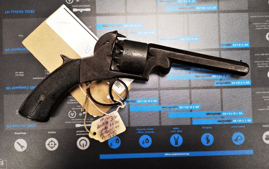
During a recent visit to my local gun shop, I was having a look through one of their cabinets when I spotted something interesting. A Webley-Bentley Revolver from the mid-1850s.
Right side of the revolver (Matthew Moss)
The Webley-Bentley was a double-action only, or as it was then known ‘self-cocking’, percussion revolver and a contemporary of the Adams revolver. Based on lock-work designed by Joseph Bentley the revolver was offered in a series of calibres. The Webley-Bentley was introduced in the mid-1850s and continued to be produced into the 1860s. This particular pistol was sold by R. Jones of Liverpool – remarkably the gun has stayed local for 160 years.
You can just make out the faint remains of the merchant’s mark – ‘R. Jones Liverpool’ (Matthew Moss)
The pistol is a .36 calibre open-top revolver, with a 5-shot percussion cylinder and a hexagonal barrel. On the left side of the pistol is a James Kerr-style rammer for loading. It’s hammer is spurless and the action is double action only. The revolvers also came in larger calibres like .40 and .45.
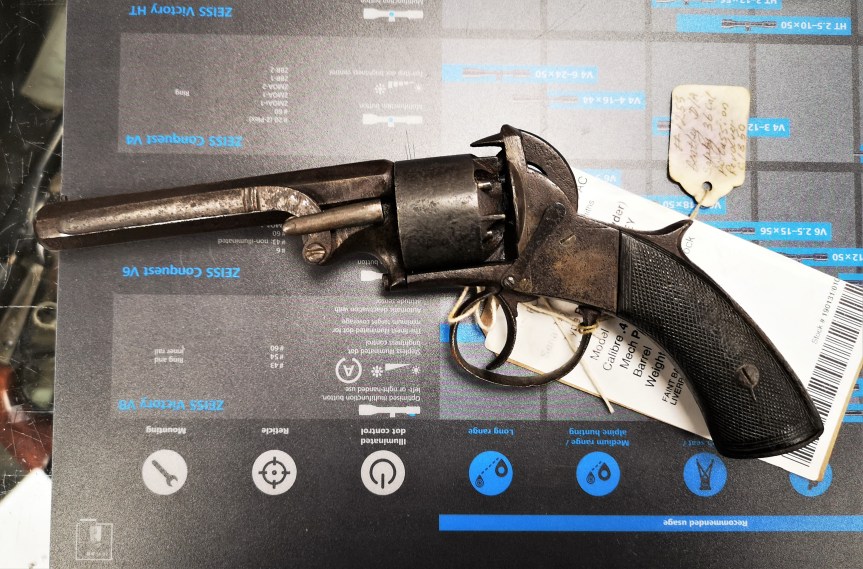
Left side of the revolver (note the rammer and spring catch) (Matthew Moss)
The overall condition of the revolver wasn’t great, but it had that worn patina of a gun that’s seen some use, which is a charm in itself. The cylinder pawl was a little worn and the timing was a little off, but it still worked and the main spring was strong. On the left side of the revolver is a flat spring catch, held to the frame by a screw, that enables the hammer to be set at half cock, for loading. In this example the post that interfaces with the hammer has long since worn.
Following on from last week’s episode on massive US Railway Guns, I thought we’d stay with the railroad/railway theme but stepping away from our figurative Armourer’s Bench for a moment to appreciate some really incredible contemporary footage.
While I was doing research for our earlier video on the M1918 Ford Light Tank, I came across this amazing footage filmed by the Ford Motor Company in 1919. It shows what appears to be a Ford Model T Touring car being hit by a train. The result, as expected, is carnage.
The footage, which is clearly staged, was filmed for a traffic safety film by Ford in 1919. While the scenario might be staged, the results certainly are not.