While doing some research in the US National Archives’ online catalogue I came across a very interesting video composed of footage from a couple of US Army Ordnance demonstrations so I thought I’d take the opportunity to talk about some very big guns.
Railway guns emerged during the late 19th century as a way of moving massive, large calibre guns which had a reach far beyond that of field artillery. Before aircraft were able to effectively attack behind enemy lines railways allowed armies to bring huge guns within range and harass their enemies lines of communication and supply.
This footage comes from Ordnance demonstrations at the Aberdeen Proving Ground in the early 1920s.
16in Coastal Gun (US National Archives)
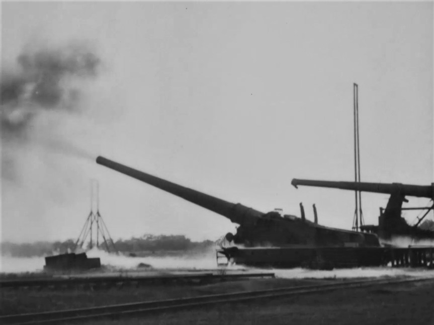
First up we have a US-built copy of the French 305mm Canon de 305 modèle 1893/96 à glissement, which according the original footage notes, was a 10in sliding mount for a gun firing a 150lb projectile. I also found some contemporary images of the gun being built at the US Watertown Arsenal, in Massachusetts, which describes it as the Model 1919. It may be the only example built by the US, Schneider built 8 of these guns for France during the war. When the gun fires we can see the whole gun and carriage recoil back a meter or so. Guns on sliding mounts cant be traversed and have to be aimed with specially laid track.
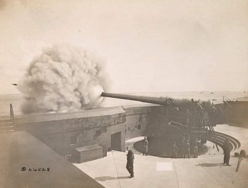
Next we have a 12 inch M1895 gun, mounted on a M1918 railway carriage which was based on the French Batignolles mount, with 360-degree traverse. Originally designed as a coastal defence gun, here’s a photograph taken in 1918 of the gun firing from a disappearing mount.
The M1895 had long been used as a coastal defence gun, and with US entry into the war surplus or unnecessary coastal guns were remounted as railway guns. The railway mounted M1895s had a large recuperator to mitigate the gun’s recoil. 12 were mounted, however, none reached France before the end of the war. We also get a nice shot of the shell hitting its target in the distance.
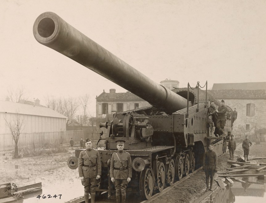
The 14 inch railway guns were the only big US guns to see action during WW1. Taking spare US Navy 14in naval guns, the 14″/50 caliber Mk 4 gun, which had been mounted in the New Mexico and Tennessee-class battleships, and mounting them in a carriage built by the Baldwin Locomotive Works. Once in position the guns had to have a recoil pit dug out beneath the carriage to allow space for the gun to recoil when it was at high elevation. They had a range of up to 25 miles.
Five Mk1 guns made it to France operating as single gun batteries manned by US Navy Sailors. The guns fired a total of 782 shells during the war, with Battery 4 firing its last shell at 10:57:30 a.m. on 11 November 1918.
Unlike the MkI guns that made it to France in this footage we see the gun without an armoured gun house, with the gunners working the gun in the open.
An M1919 16in Coastal Gun in a Barbette mount (US National Archives)
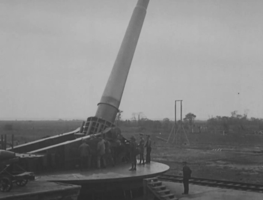
Finally, we have the truly massive 16 inch M1919 coastal gun . Designed for the Army Coast Artillery Corps to defend the US’ major coastal ports the 16-inch gun could throw a 2,340 lb shell up to 28 miles. In this footage we can see the gun mounted on an M1919 barbette carriage which could be elevated up to 65-degrees.
This second piece of footage dates from between 1929 and 1931, with dozens of West Point cadets gathered eagerly to see the gun in action.
Demonstration of Ordnance Materiel at Aberdeen Proving Grounds, 1920-1926 (source)
Railway Artillery: A Report on the Characteristics, Scope of Utility, Etc., of Railway Artillery, Vo.1, H.W. Miller & US Ordnance Dept. (1921) (source)
Railway Artillery: A Report on the Characteristics, Scope of Utility, Etc., of Railway Artillery Vol.2, H.W. Miller & US Ordnance Dept. (1922) (source)
The United States Naval Railway Batteries in France, E. Breck (1922) (source)
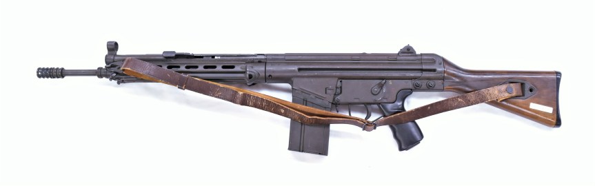
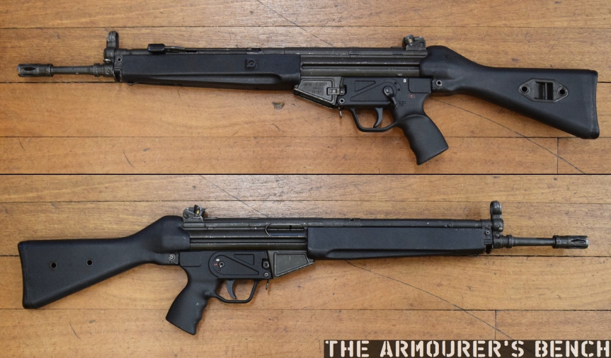
We’re all familiar with the Heckler & Koch G3 and its roller-delayed blowback action. What is less well-known is that H&K were one of two companies originally contracted by the West German government to produce the Bundeswehr’s new service rifle. The other company was Rheinmetall and today we’re lucky enough to be taking a look at an example of an early production Rheinmetall G3.
Left side (courtesy of the Cody Firearms Museum)
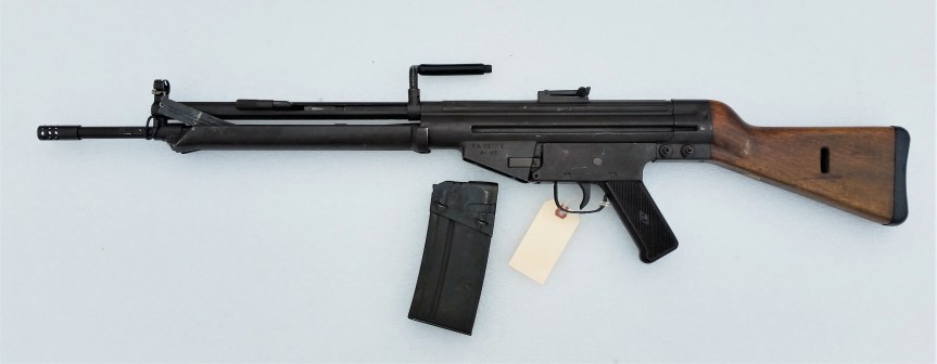
The rifle which became the G3 was of course originally developed by German and Spanish engineers working at the Centro de Estudios Tecnicos de Materiales Especiales (CETME) and was intended to equip the Spanish armed forces. Initially, the West German Bundesgrenzschutz (border guards) were interested in purchasing a substantial number of the new CETME rifles, with an initial order for 5,000 agreed, however, in September 1955 the order was cancelled due to delays in production and the Bundesgrenzschutz subsequently ordered the FN FAL instead.
In November 1955, the Bundeswehr (West German military) was formed and began to search for a suitable new 7.62x51mm service rifle. Having observed the Bundesgrenzschutz’ testing the fledgling Bundeswehr took an interest in the CETEME rifle. 400 ‘STG CETME’ rifles were ordered for troop trials and these were assembled in Germany by Heckler & Koch. The rifles were delivered in late 1956, and comparative trials against the FAL began the following year.
CETME Model A (Courtesy of P. Hokana)
The trials found the ‘STG CETME’ to be satisfactory in terms of features and design but lacking in durability. A number of small changes were requested including a flash hider suitable for launching rifle grenades, either a flip-up or dioptre rear sight instead of a traditional tangent style, a case deflector, a simpler more ergonomic pistol grip, a longer more ergonomic cocking handle, changes to the recoil spring guide and tweaks to the shape of the buttstock. Additional improvements such as a stronger bipod, lighter magazine, a last round hold open mechanism, overall lightening of the rifle, a lighter 20-round magazine and a proper handguard were also requested.
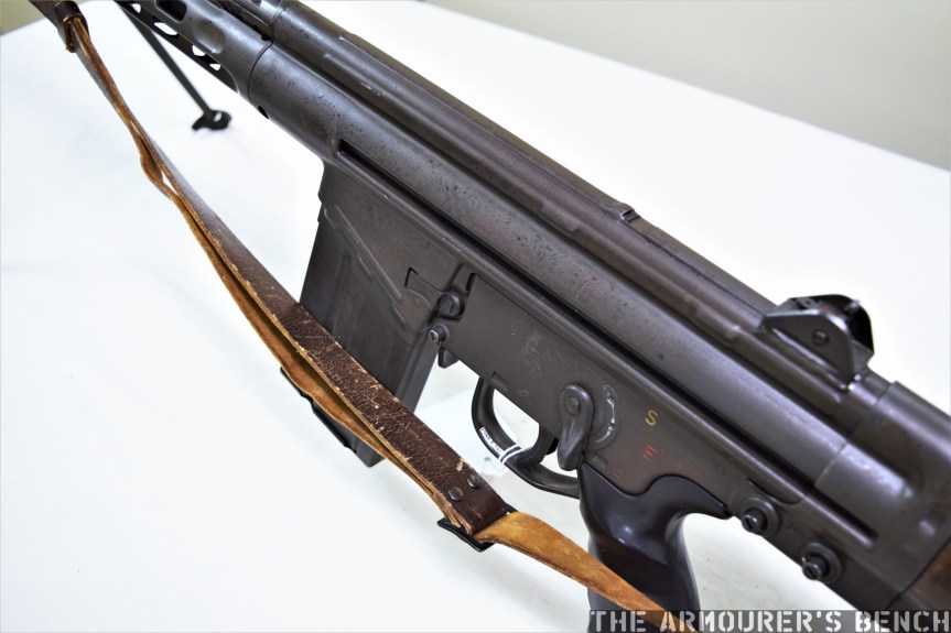
Left-side of the G3’s receiver, note the partial reinforcing rib on the magazine housing (Matthew Moss)
FN were unwilling to grant Germany a manufacturing license and the $110 per rifle price for the FAL proved substantially higher than CETME’s production estimates (The ArmaLite AR-10, J. Putnam Evans (2016), p.204). With adoption looking likely, legal wrangling over patent ownership began between Mauser, Rheinmetall and Heckler & Koch. All claimed the ownership of the roller-delayed blowback principle used by the CETME rifle. Eventually, however, the West German government awarded Rheinmetall and H&K future production contracts for the new rifle with the government supporting H&K’s claims but the legal battles continued for almost a decade.
In the meantime, with production of the CETME rifle not yet initiated and in light of some durability/reliability issues suffered during the STG CETME’s troop trials, 100,000 ‘Series C’ FN FALs were ordered for the Bundeswehr in late 1956. In 1957 the Swiss SIG 510 (designated the G2) and the American ArmaLite AR-10 (designated the G4) were also evaluated. Once the modifications requested after the troops trials were completed by H&K, a run of twenty rifles was produced and tested again.
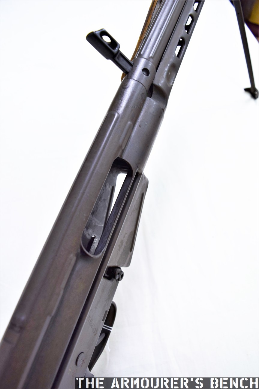
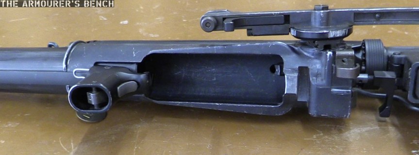
A view inside the ejection port of the G3 with the charging handle locked back (Matthew Moss)
In 1959, the West German government finally adopted the CETME rifle, designating it the G3. The German federal government decided that they wished to purchase the worldwide manufacturing rights to the G3, which naturally the Spanish government was reluctant to agree to. An agreement was finally reached in January 1958 and the contract giving West Germany worldwide rights to the G3 was finalised on February 4th, 1959.
One issue was that in June 1957, CETME had agreed a licensing deal for manufacture and sale of the rifle with a with a Dutch company Nederlandsche Wapen en Munitiefabriek (NWM). In order to gain the manufacturing rights sold to NWM the German government awarded the Dutch company a lucrative contract producing 20mm ammunition (Full Circle, p.234).
A close up of the trigger mechanism housing, note ‘Germany’ faintly scratched into the surface (Matthew Moss)
Interestingly, as the German government owned the manufacturing rights, H&K initially had to pay the government 4 Deutsche Marks per rifle, despite having been awarded the contract by the German government. In late January 1959, H&K were awarded the first substantial production contract, amounting to 150,000 rifles. Rheinmetall were subsequently awarded a similar contract (Full Circle, p.235).
According to R. Blake Stevens’ book on the roller-delayed blowback action, Full Circle, Rheinmetall produced 500,000 G3s during the 1960s, delivering 8,000 rifles per month (Full Circle, p.287). As H&K had been designated as the technical lead on the G3 project, Rheinmetall’s engineers made no attempts to develop modifications or improvements and even when H&K had switched to plastic furniture the Rheinmetall guns continued to use wood. Rheinmetall’s only other G3-related project was the RH4, a 7.62x39mm chambered, roller-locked but gas-operated rifle designed for export (Historical Firearms).
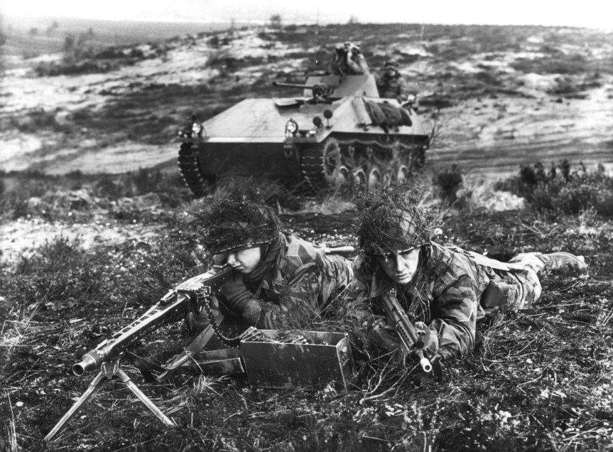
W. German Army Armoured Reconnaissance car, with MG3 team with No.2 armed with G3, c.1960 (US Army)
In addition to the G3, Rheinmetall were the sole manufacturer of the MG3 machine gun, the 7.62x51mm MG42. Blake Stevens explains that in 1969, when a new tender for MG3 production was due, that H&K moved to undercut Rheinmetall who had until now held the monopoly on MG3 production (Full Circle, p.292). As a result an agreement was reached where Rheinmetall retained their monopoly on MG3 production and H&K became sole manufacturer of the G3 for the West German military.
Examining An Early Production Rheinmetall G3
The G3 went through a large number of changes both before and after it went into service. The rifle we’re examining today is a good example of an early production rifle, as adopted in 1959. This rifle is lightly marked with ‘G3 [Rheinmetall’s ‘star-in-a-circle’ logo] followed by a serial number of 745 and below that it is date marked with the ‘3/60’, for March 1960.
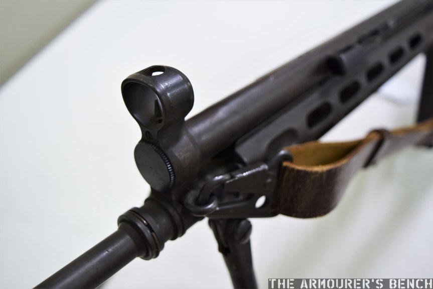
A close up of the G3’s front sight and sling attachment point (Matthew Moss)
Working our way from the muzzle back; the rifle has the early style of flash-hider/grenade launcher support which was introduced in 1957 and altered in early 1961, an enclosed front sight and a detachable bipod (which was not Bundeswehr general issue). It has a stamped metal handguard which was replaced by one with a wooden insert in 1961, before H&K introduced plastic furniture in 1964.
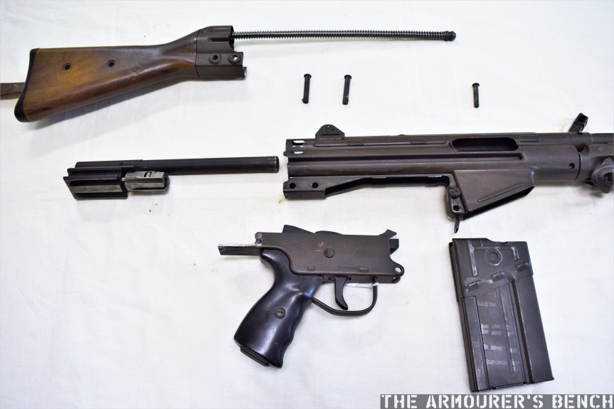
The G3 field stripped (Matthew Moss)
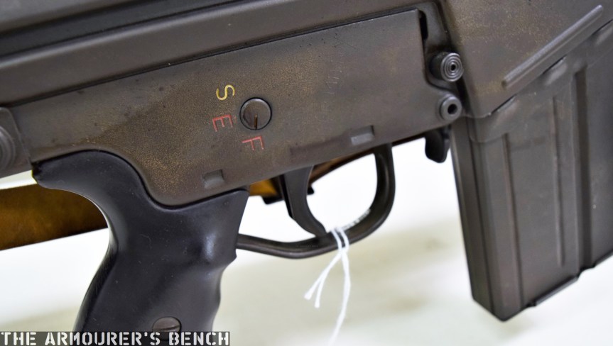
The folding carrying handle seen on the troop trials rifles has been removed, the receiver is stepped for the attachment of a scope base and the magazine housing has a single strengthening rib, rather than the later ‘full-frame’ continuous rib. It has an S-E-F selector (S – Sicher/safe, E – Einzelfeuer/semi, F – Feuerstoß/auto) and black plastic pistol grip. Internally, the rifle has a captive mainspring. Unlike later G3’s the rifle has a 2-position folding L-shape rear aperture sight with apertures for 200 & 300 metres rather than the later dioptre sight adopted officially in mid-1960. The rifle has a wooden stock held with a stamped metal sling attachment and a plastic buttplate.
When the US entered World War One in April 1917, the US Army had no experience with tanks. American observers in France had reported on the early Allied uses of tanks at the Somme and American enthusiasm for the new machines was lacking in many of the Army’s upper echelons.
This began to change after the arrival of General Pershing and his staff in France, ahead of the American Expeditionary Force. Pershing directed that a Tank Corps be raised and detailed a number of officers, including the enterprising young officer, Captain George S. Patton, to establish a training ground and report on how best to deploy tanks.
Patton was instrumental in shaping the US Army’s early tank doctrine, he wrote a highly detailed report on how to deploy tanks to maximum effect. Patton, a cavalry officer by training, admired the French Renault FT’s speed, mobility and manoeuvrability but felt the two doctrines of French light and British Heavy tanks could be combined. In December 1917, Colonel Samuel Rockenbach was placed in command of the new, but still tank-less, US Tank Corps.
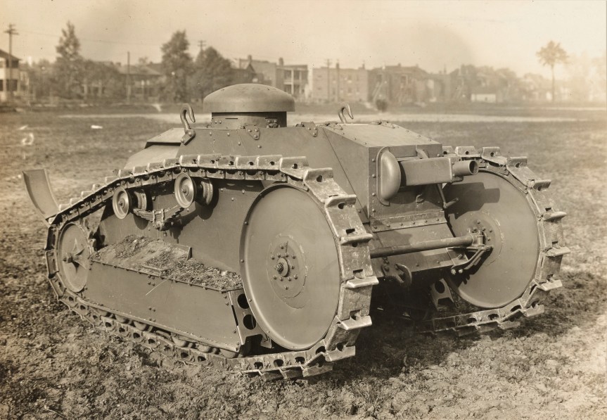
A Ford Model 1918 Light Tank, weighing 3 tons it was armed with a single .30 calibre machine gun (US National Archive)
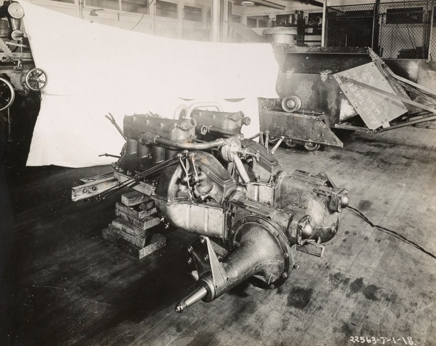
Britain and France shared their tank designs with the US but in early 1918, the American automobile giant, Ford, began work on an American light tank. The result was a light and mobile tank weighing in at 3 US tons (or 2.7 metric tons). Sometimes referred to as the Ford 3-Ton Tank or the Ford Model 1918. Ford hoped to produce the new tank using as many off the shelf components, from their automobile and truck production, as they could. So the new tank was powered by two 4-cylinder Ford Model T engines, in theory developing around 40 horsepower, with a maximum speed of 8 mph and an operational range of just over 30 miles. Taking cues from the French FT, the M1918’s engines, fuel tank and transmission were mounted in a compartment at the rear of the tank. Some sources note that the tank was developed with the assistance of the Van Dorn Iron Works, in Cleveland, Ohio, presumably assisting in the manufacture of bullet-proof steel plates making up the tank’s armour.
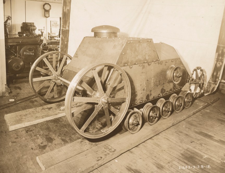
An early version of the 3-Ton Ford being assembled in one of Ford’s Detroit workshops (US National Archive)
Contemporary photographs show the prototype during assembly in one of Ford’s Detroit workshops. We’re extremely lucky to have these photos showing the development process, they show that the initial shape and layout changed very little but some important changes were made as the tank was tested. The photographs date to April 1918, suggesting that by late spring the first prototype was assembled.
Like the French FT, the M1918 had a two-man crew but was significantly lighter weighing 4 tons less. The Ford could reach speeds of up to 8 mph while the slower FT could achieve around 5 mph. The Ford M1918 was 14 feet (or 4.3m) long, making it slightly shorter than the FT. The Ford’s armour was much thinner than its French counterpart, while this helped with weight, it would have left the crew vulnerable. It had just 7 to 13mm of armour compared to the FT’s 8 to 22mm. The tank’s tracks were also extremely narrow, and while the tank was light, this could have conceivably led to issues with getting bogged down in thick mud. Some of the contemporary footage of the prototype shows it with wider, more practical looking, tracks but the later pre-production models seem to have reverted to the narrower tracks.
The M1918 was powered by a pair of 4-cylinder Model T engines (US National Archive)
The earlier prototype Ford tank did not have a gun fitted and the front doors for both driver and gunner were hinged at the sides, rather than at the top. Some of the contemporary footage shows the gun-less prototype becoming trapped nose-up, at an almost 90-degree angle, after trying to cross a relatively narrow trench. To prevent this we see that the later tanks were subsequently fitted with a ‘trench tail’.
In terms of armament, the Ford was also limited with a single .30 calibre machine gun, mounted on the right side of the hull in an armoured casement. The casement doesn’t appear to have a prominent sight aperture or vision slit for the driver so how the gun was aimed is unclear. The gun also appears to have a very limited firing arc compared to the FT’s turret mounted gun, which could rotate a full 360 degrees. It is unclear exactly what sort of gun was going to be mounted in the tank although an Hotchkiss M1909 Benét–Mercié (also used in British tanks) may have been an option. Another more likely option would have been the specially-developed M1919 air-cooled Browning Machine Gun, which had been specially developed for tank mounting. Judging from the size of the armoured housing for the gun, however, it may have been intended to mount the M1918 Marlin Tank Machine Gun, which had large aluminium cooling fins.
If we look closely we can see that the gunners hatch appears to be hinged, suggesting it can be opened too. Just to the right of the gun there is a round hole in the armour with what appears to be a starting handle sticking out of it (US National Archive)
The Ford had a two-man crew with the driver on the left and a gunner on the right. The driver also had a cupola, with vision slits, on the roof of the tank which allowed him to drive when the hatch was closed. But this must have been difficult to see out of unless the driver changed his driving position.
The tank had an exposed front axle connecting its large front track idlers, this would have been susceptible to damage from enemy fire and from hitting obstacles. At the rear is the drive sprocket and along the body of the tank are two sets of three suspension wheels with two track support rollers above. Note that the support rollers are mounted on a truck leaf spring, another example of off-the-shelf parts being utilised. This represents a change from the single support roller seen in the earlier prototype
The later footage shows as many as half a dozen pre-production tanks on the move during a demonstration at Ford’s plant in Detroit. We get a good feel for how fast and manoeuvrable the Ford tanks were. But they also struggle to navigate some of the more difficult terrain and don’t appear to have the power or traction to tackle some of the steeper hills or ditches. The tanks much have been difficult to steer, likely using a pair of clutch levers to control the tracks on either side. Two tanks even collide with each other and there’s a couple of other near misses as the Ford’s navigate around the test area. One tank becomes stuck requiring two others to pull it clear of the bank.
Six pre-production Ford M1918s lined up before a demonstration (US National Archive)
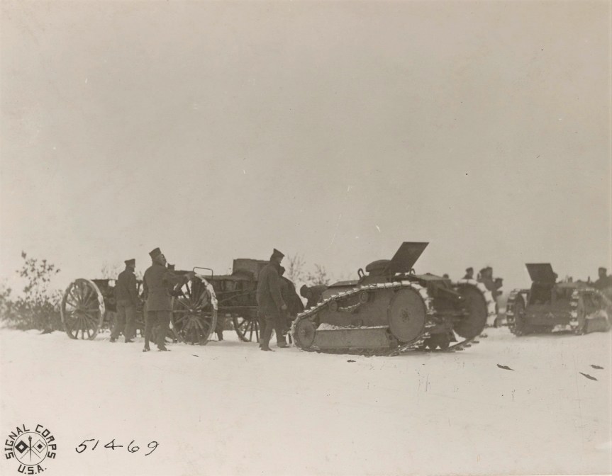
The War Department was eager to get tanks into production ordering 15,000 M1918s from Ford, with 500 to be delivered in January 1919 with production continuing at 100 per day after that. An initial batch of 15 were ordered for testing. At least one of these was sent to France for evaluation before the end of the war. The French were unimpressed finding it inferior to the FT, they did consider it as an artillery tractor for the French 75. The US also considered the Ford for this role and some photograph captions from early 1919, of Battery A, 140th Field Artillery, describes it as a ‘3-ton tractor’ for pulling “the new American 75mm split trail gun”, the M1916. These photographs also prove that more than one M1918 reached France.
Several Ford M1918s in use as ‘3-ton tractors’ for pulling the M1916 75mm gun, taken at the Artillery Training School in Le Valdahon, in 1919 (US National Archives)
The Ford tanks were not well regarded by those with practical experience, with the men of the US Tank Corps in France not consulted about the tank before it was ordered by the Ordnance Department. The war ended before large scale production of the M1918 could begin, With just 15 M1918s built we’re lucky to have this much film of it in action. Today only two of the Ford light tanks survive in US Army collections.
A post-war development of the Ford, note the slightly different gun mount, now in a ball mount with a prominent aiming aperture, this photograph was tank in early 1919 – gun type unknown (US National Archives)
In reality the M1918 was more a Machine Gun Carrier than a tank. How effective it might have been is a matter of speculation. It’s difficult to say, while the French may not have felt it was an improvement over the FT, it certainly showed enough merit for the War Department to make a large order. Its narrow tracks, lack of protection and minimal armament may have proved to be problems. The M1918’s real legacy is that it while the US had built other tanks during the war, including the M1917, a copy of the FT, and the MKVIII heavy tank, in collaboration with the British, the M1918 Ford was the first truly American designed and built tank.
The Illustrated Encyclopaedia of Military Vehicles, I.V. Hogg & J. Weeks (1980) The Complete Guide to Tanks & Armoured Fighting Vehicles, G. Forty & J. Livesey, (2012) Camp Colt to Desert Storm: The History of U.S. Armored Forces, G.F. Hofmann & D.A. Starry (1999) The Machine Gun: History, Evolution, and Development of Manual, Automatic, and Airborne Repeating Weapons, G.M Chinn (1951)
Introduce in British service in 1938, the Bren remained in use into the 1990s. Based upon the Czechoslovakian series of ZB light machine guns, its name comes from an amalgamation of its origins: BR for Brno, the factory in Czechoslovakia, and EN for RSAF Enfield where it had been adapted for British service and was to be produced.
The Bren is chambered in .303, is gas operated and fires from an open bolt. It feeds from a top-mounted 30 round box magazine, as such the sights are offset to the left meaning the Bren can only be fired from the right shoulder – which as a lefty, I quickly realised.
Bren Mk1(Modified) (Matthew Moss)
This example does not have the scope mounting dovetail machined into the left side of its receiver, or the folding grip and the hinged shoulder rest indicating that it is a Mk1 (Modified) ‘Pattern A’ gun, which was introduced after the evacuation of Dunkirk, the British Expeditionary Force lost most of the 30,000 Brens that had been taken to France. Only around 2,000 remained in inventory in the summer of 1940, so increasing production was essential, this model and the even more simplified MkII were introduced. While at the same time the BESAL light machine gun was developed as an emergency alternative by BSA – check out our earlier video on the BESAL here.
The BSA-developed BESAL light machine gun (Matthew Moss)
As a Mk1, the gun has the original profile buttstock, with the fitting for a rear folding grip and tripod attachment point as well as a buttcap. It also has the drum rear sight rather than the later ladder sight of the Mk2 & 3. It also had a folding cocking handle and this Mk1(M) gun also has the earlier pattern height adjustable, rather than fixed, bipod legs. This gun is marked ‘MK1, with an E within a D, 1942’ indicating it was made at RSAF Enfield.
Bren Mk1(Modified) with magazine off and dust cover closed, note the drum sight but lack of receiver cut for optic (Matthew Moss)
The Bren’s relatively slow rate of fire (of around 500 rounds per minute) makes it controllable and very easy to fire single shots while in full auto. The Bren does, however, have a selector on the left side of the gun, just above the trigger guard, which can be set to safe, semi or fully automatic. The Bren has a rocking recoil impulse as its heavy bolt moves back and forth, easily manageable if held tightly into the shoulder with the off-hand holding onto the wrist of the stock. The top-mounted magazine when fully loaded does have a tendency to want to fall to the side but once you’re used to this it’s not really an issue. The legend surrounding the accuracy of the Bren is certainly somewhat valid, at the time it was recognised as an accurate weapon and I found it accurate from my short time behind the trigger. I found the Mk1’s rear sight aperture and drum adjustment easy to use.
Spent cases eject out of the bottom of the receiver, the weapon had a sliding dust cover for when the magazine was removed and the charging handle is non reciprocating and folds forward.
Bren Mk1(Modified) with magazine off, dust cover closed and barrel removed (Matthew Moss)
The Bren has a quick change barrel system. To remove the barrel the release catch in front of the magazine was rotated upwards to unlock and then the barrel was rotated 90 degrees clockwise by bringing the carrying handle up to the 12 o’clock position and then sliding it forward.
We’ll have a more in-depth look at the Bren and its Czech predecessors in the future. My thanks to my friend Chuck over at Gunlab for letting me put some rounds through his Bren, I got a real kick out of it!
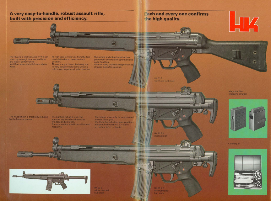
Heckler & Koch’s first 5.56×45 rifle, the HK33, was introduced in the late 1960s as a response to the emergence of the new 5.56x45mm round and the introduction of the FN CAL. The HK33 is little more than a scaled down version of HK’s successful 7.62×51 G3. Developed by Tilo Möller, the HK33 used the same roller delayed blowback action and shares most of the G3’s features.
Left & right views of the HK33 (Matthew Moss)
It has a stamped receiver and uses the same plastic furniture and pistol grip/trigger mechanism housing as the G3. The rifle is 39 inches or 92cm long and is by no means a light weapon, weighing around 4kg or 8.7 lbs. The HK33 feeds from 25, 30 or 40 round proprietary HK magazines.
The rifle came in main two main variants a full length version with a fixed stock, which could be fitted with a collapsing stock, and a shortened K-variant with a shorter barrel. The weapon came with either a safe, semi and full auto or safe, semi, 3-round burst fire control mechanism.
HK factory brochure showing the variants of the HK33 (Heckler & Koch)
The HK33 was not adopted by the West German Army, however, it did see extensive use with Germany’s federal state and police forces and the Bundeswehr special forces. While it wasn’t adopted at home it was a successful export weapon with dozens of countries purchasing and adopting the rifle. France tested the improved HK33F in the Army 1970s and although it performed well the FAMAS was adopted instead. A production license was sold to Thailand who adopted the HK33, purchasing 40,000 rifles and the license to manufacture 30,000 more. Thailand also developed their own unique bull pup version of the rifle, the Type 11.
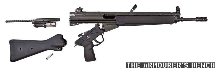
HK33 field stripped (Matthew Moss)
Malaysia also purchased 55,000 HK33s and the Spanish Guardia Civil used them for a time. The manufacturing rights for the HK33 were also sold to Portugal for production at Fabrica Militar de Prata and to Turkey where it remains in production at MKEK.
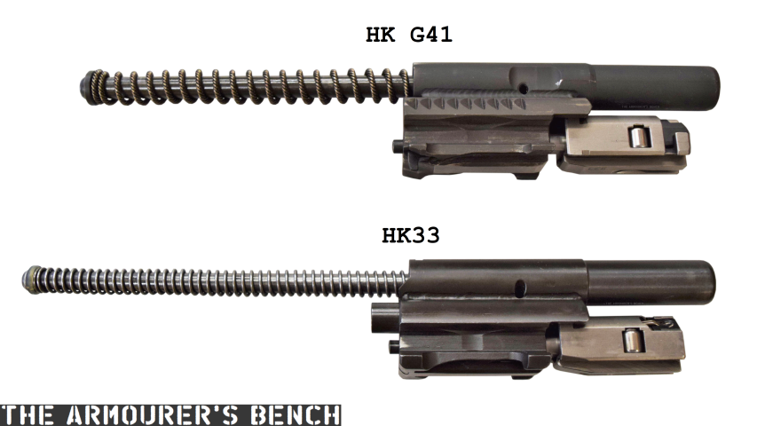
A comparison of the HK33’s bolt with the later HK G41 (Matthew Moss)
HK produced the HK33 from 1968 through to the late 1980s. It also provided the basis for the HK53 5.56 ‘submachine gun’ which we have covered previously. It was also the basis of the less successful G41, which we’ve also covered in a full length episode, you can find this here. The similarities with the HK33 are easy to see but the G41 has a number of subtle changes.
If you enjoyed the video and this article please consider supporting our work here.
I’m very pleased to announce that we now have some ‘Thank You’ perks for everyone that supports TAB on Patreon!
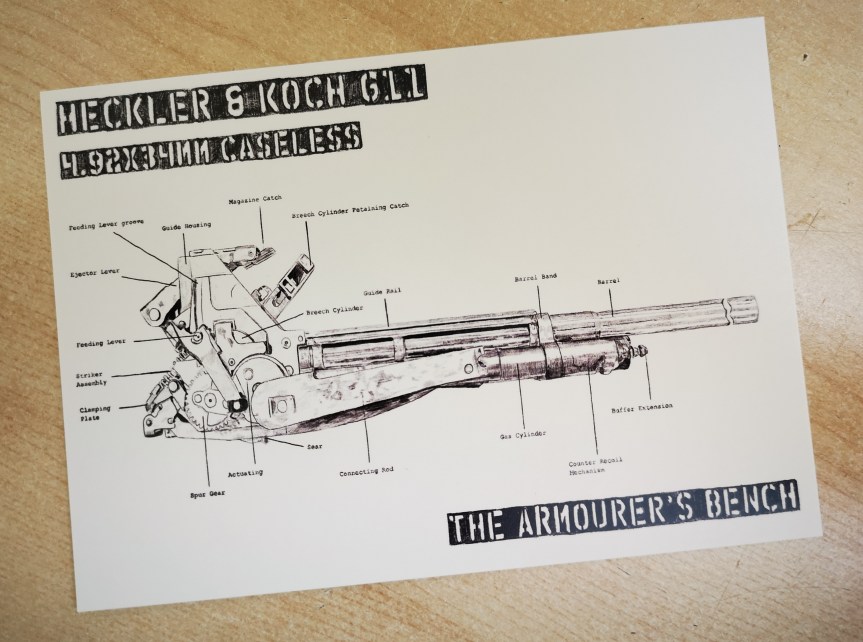
All Patrons will continue to get access to our regular sneak peek and behind the scenes blogs about what we’re working on and what’s coming up and in addition: $1 Patrons will get a thank you postcard featuring some very cool, specially commissioned art – an illustration of the inner working of the Heckler & Koch G11!
$5 & up Patrons will receive the G11 postcard AND a 2×6″ (5cm x 15cm) The Armourer’s Bench logo sticker!
We’re really excited to be able to offer tangible perks to say thank you for your support. In order to cover postage costs we’ll send off the perks once you’ve been a supporter for a month – this is purely to cover the postage costs (for instance it’s just over £1.20/$1.60 to post a postcard to the US from the UK) to where ever you are around the world!
TAB is an entirely viewer supported project so we can’t tell you how excited we are to finally have a way to thank you for going that extra step and supporting our efforts with your own hard earned money. Thank you to all our existing Patrons (who will of course be able to get their hands on the new Perks right away) and thank you for reading this and considering becoming a TAB Patron.
The British Army entered the First World War with very few mortars, and certainly none at the battalion level. As the stalemate of trench warfare set in and the effectiveness of enemy mortars became clear it was decided that trench mortars of various sizes would be needed.
Nicknamed ‘plum pudding’ or ‘toffee apple’ mortars after their projectile’s characteristic shape, the 2 inch Medium Mortar or 2 inch Trench Howitzer, was one of Britain’s first effective light trench mortars to be introduced.
Right-side view of the 2in Trench Mortar (Matthew Moss)
Trench mortars were the army’s most forward artillery, right up on the front line. These short range weapons were able to throw large, high explosive projectiles, short distances across No Man’s Land at the enemy trench system opposite. The 2 inch mortar was considered accurate out to 350 yards with a maximum effective range out to just under 600 yards.
Introduced in 1915, the 2 inch mortar was originally crewed by men taken from the battalion it was stationed with, along with some specialists from the Royal Artillery. However, with the introduction of the 3 inch Stokes mortar which was operated by the infantry themselves the 2 inch mortars became the sole responsibility of the Royal Field Artillery.
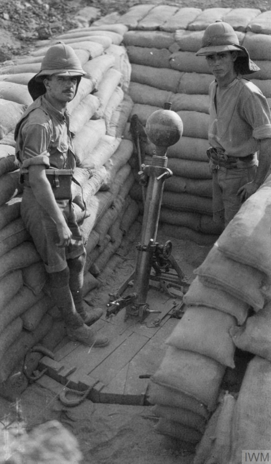
A young gunner loads a 2in spigot mortar bomb into his mortar (Imperial War Museum)
Mortar positions were often in secondary trenches just behind the infantry’s frontline. This was to help protect the infantry from potential counter-battery fire. The trench mortars were often deployed to sectors to provide counter battery fire against German minenwerfers or in the run up to an offensive or local action. A British Army report on artillery use, drawn up in February 1917, noted that “Owing to their liability to be destroyed by hostile artillery fire it may often be advisable to defer opening fire with these mortars till the last day of bombardment.” The mortars were also tasked with keeping gaps made in the wire clear and with supporting any feint attacks made by infantry during gaps in the bombardment running up to a larger offensive.
Llewelyn Wyn Griffith, a captain with the 15th Royal Welch Fusiliers and later a novelist, recalled in his war memoir:
“At night a trench mortar officer set his guns in a derelict trench about twenty yards behind the line and carried up his ammunition, heavy globes of iron with a little cylindrical projection like a broken handle. In the morning I moved the men from the bays between the trench mortars and their target, to lighten the risk of loss from retaliatory fire.”
Sometimes the width of No Man’s Land required saps to be cut extending out from the frontline so the mortar rounds didn’t fall short. The 50 lb lollipop-like projectile had a maximum effective range of 570 yards (depending on the size of cordite charge used), and could create a crater 5 feet deep and 14 feet wide. The ideal mortar position was a 6 feet wide by 9 feet deep sandbagged pit with the weapon’s heavy wooden bed at the bottom and room for the crew to load the mortar.
A British 2in Mortar position in Mesopotamia, note the ignitor’s breech is open (Imperial War Museum)
Crews could manage to fire approximately once every two minutes. Much slower than the lighter 3 inch Stokes Mortar and but faster than the heavy 9.45 inch Heavy Mortar. The mortar comprising of just its tube, bed, stand and ignition system weighed 320 lbs (145kg), not including the accompanying tools and the Temple silencer system which could be fitted (which weighed 47 lbs or 21 kg alone).
Typically manned by a 5 man mortar crew comprising of an NCO, gunners, and ammunition bearers. To operate the 2 inch mortar a cordite charge was first placed down the tube, the projectile’s shaft was then inserted on top of the charge, the projectile’s fuse was set and checked and a new blank cartridge chambered in the ignition system. The crew then got clear of the weapon and pulled the lanyard to fire the mortar. To reload the crew ran a clearing stick down the tube and then repeated the loading process.
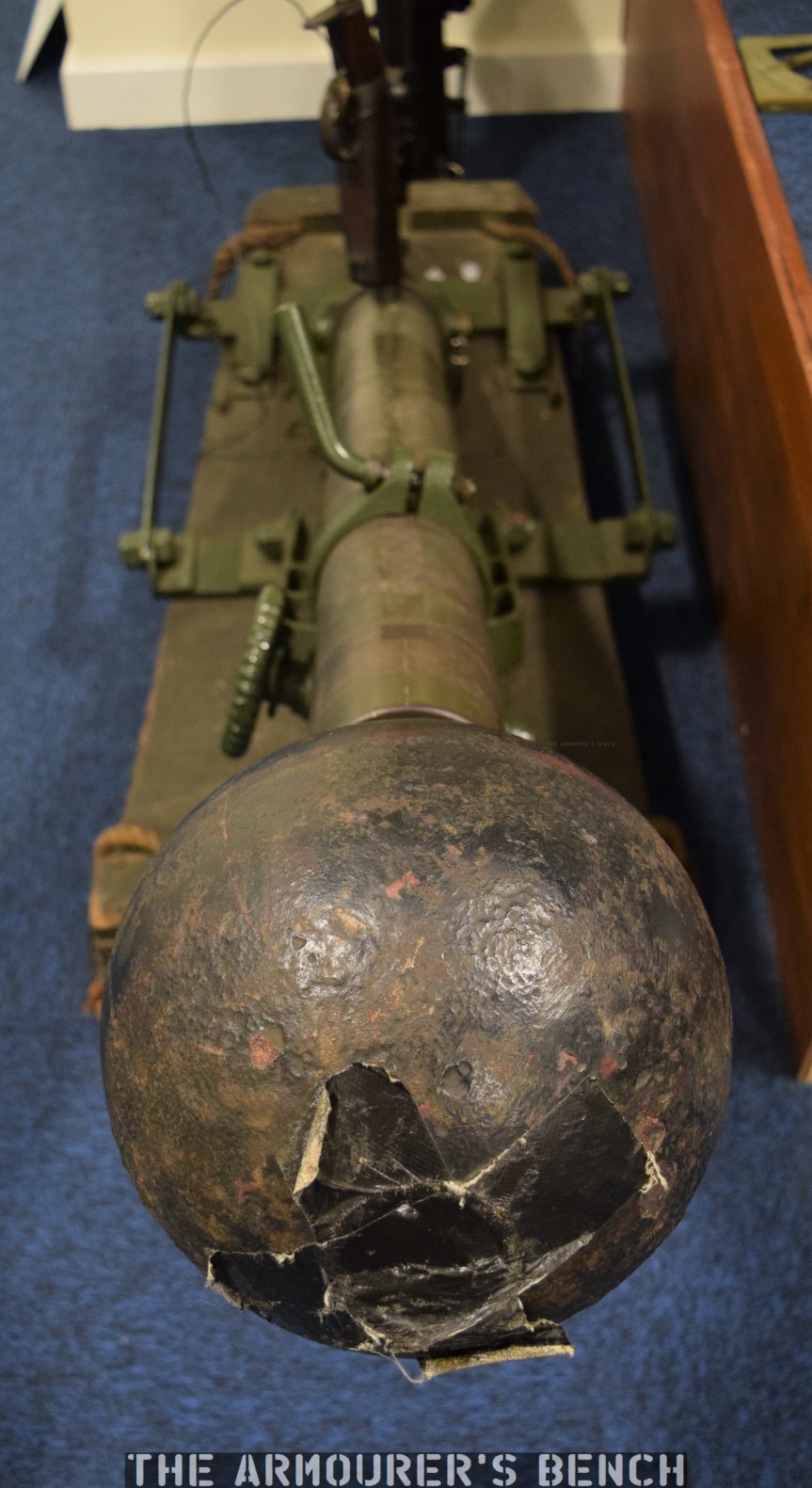
The business end, a view down the length of the mortar (Matthew Moss)
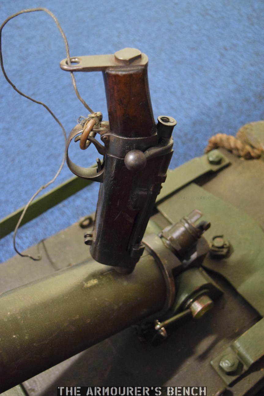
Interestingly, the 2 inch Medium Mortar, like the larger 9.45 inch Heavy Mortar used a cut-down rifle, which screwed into the ‘breech’ end of the mortar tube. This particular mortar has an 1894-dated cut down Lee-Enfield MkI as its ignition system, the cutdown rifle has a wooden insert in its magazine well but it still has its rear volley sight attached. This reusable system replaced the T-tube Friction ignitor, which was in high demand by Britain’s bigger guns. The Lee-Enfield-based system enabled the cordite propellant charges to be ignited by a blank .303 round instead. The rifle’s trigger was pulled with a lanyard from nearby cover. These cutdown ignitor rifle are sometimes confused for Obrez-style Lee-Enfields.
A close up look at the 2in Mortar’s SMLE ignitor (Matthew Moss)
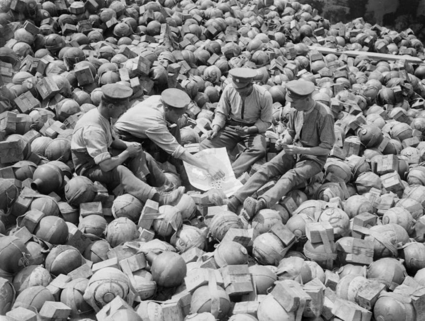
The weight of the cordite charge used dictated the range while a variety of different fuses were used with the projectiles, these screwed into the nose of the bomb. The sphere was about 9.3 inches in diameter with a 2 inch thread for the fuse at its head and a cup for the 22 inch long, 2 inch thick solid cast iron stick or spigot at its base. The sphere was filled with high explosive (Amatol or Ammonal). The high explosive bombs were painted white with a green or pink stripe around their middle.
They were often deployed in batteries of four with three Royal Field Artillery medium mortar batteries attached to each division. The mortars were predominantly tasked with cutting enemy barbed wire and destroying enemy trenches and forward positions, such a machine gun nests.
Men of the Royal Army Ordnance Corps playing cards on a dump of trench mortar ammunition during Battle of the Somme (Imperial War Museum)
Captain Griffith described a battery of 2 inch mortars opening fire on enemy lines:
“A pop, and then a black ball went soaring up, spinning round as it went through the air slowly; more pops and more queer birds against the sky. A stutter of terrific detonations seems to shake the air and the ground, sandbags and bits of timber sailed up slowly and then fell in a calm deliberate way. In the silence that followed the explosions, an angry voice called out in English across No Man’s Land, ‘YOU BLOODY WELSH MURDERERS.’
The 2 inch medium mortar entered service in spring 1915 and remained in use into 1917 with British and Empire troops. It was used on the Western Front and in Mesopotamia. Over 800 were ordered initially with 675,000 bombs, many of the mortars were made in railway and agricultural machinery workshops, allowing larger factories to focus on more complex weapons. The 2 inch mortar was superseded by the larger bore Newton 6 inch mortar later in the war. Some of the remaining 2 inch projectiles were re-purposed as makeshift anti-tank mines, buried in no man’s land in anticipation of possible German tank attacks.
If you enjoyed the video and this article please consider supporting our work here.
The interwar period saw many countries under invest in their militaries, Britain was no exception. One area of equipment that went lacking for many years was adequate anti-tank weaponry. This was finally addressed in the mid-1930s with the Superintendent of Design at Woolwich arsenal developing the 2pdr anti-tank gun, which adopted in 1936.
Prime Minister Winston Churchill watches a demonstration of a 2pdr AT gun (Imperial War Museum)
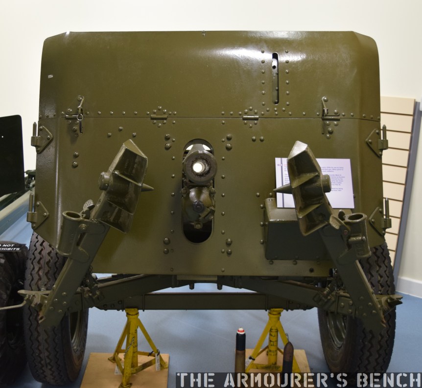
Officially designated the ‘Ordnance QF 2-pounder Mark IX’, the 2pdr was an attempt to provide a light and mobile high velocity anti-tank gun which was relatively cheap to produce and effective against contemporary tank armour. It was also intended that the gun would itself be mounted in armoured vehicles and tanks.
In 1934 development contracts were awarded to Woolwich and the Vickers-Armstrong company for the design of carriages for the new gun, the Vickers Mark I and the Mark II from Woolwich. The Mark I had a slightly different armour shield and leg design.
These two carriages were tested against one another with trials taking place from November 1935 through to the summer of 1936. The Vickers design initially won out and the first order for 44 guns was placed in 1936. A subsequent re-evaluation of an improved version of the Woolwich carriage found it superior and the Mark II carriage was adopted.
The business end, note the 2pdr’s tall armour shield to protect the crew (Matthew Moss)
The 2pdr fired a 40×304mmR armour piercing round which weighed 2lbs 6oz or 900g and was effective out to 1,000 yards against up to 1.5 inches of armour. It had a four man crew and was capable of firing up to 20 rounds per minute. It had an all steel barrel with a removeable breech ring and a vertically sliding breech block. The gun had an innovative and very stable three-legged collapsible platform, rather than a split-trail carriage, that also allowed the gun to be rotate through 360 degrees when its road wheels were removed. The 2pdr had a semi-automatic action with a hydraulic/hydrospring recoil system which used hydraulic fluid to absorb the gun’s recoil. This allowed the gun to be rapidly aimed and fired despite recoiling approximately 20 inches (or ~50cm).
A number of variants of the gun were developed during the war, with the original Mark IX, a simplified production model the Mark IXA, the Mark X which had a barrel made of higher-yield steel which was not autofrettaged – making it easier to manufacture and the Mark XA which was produced to lower tolerances and able to use the Littlejohn adapter.
Here’s a Royal Army Ordnance Corps training film on the 2pdr (courtesy of the AWM) in full:
Weighing around 1,800lbs or 816kg (or 4/5 of an Imperial Ton) the 2pdr was deemed to be too heavy for the infantry it had been designed for and in 1938 it was transferred to the Royal Artillery. Typically the guns were grouped together in anti-tank battalions each with three batteries made up of four troops which operated four guns each. That’s 16 guns per battery and 48 guns per battalion. Typically a battalion would be assigned to support a division. They were designed to be towed by a variety of vehicles with trucks, jeeps and Universal Carriers often being used.
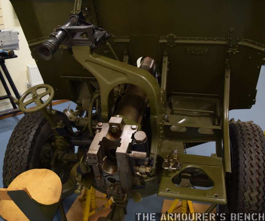
The 2pdr was typically equipped with a No.24B 2x sighting telescope, located on the left side of the gun. It also had an iron sight but the armoured shield had to be lowered to use it. On the right side of the breech an ammunition box, holding 16 rounds was be stored for easy access, another two boxes holding 8 rounds each could be strapped to the carriage behind the ammunition box (described as the emergency ammunition box). The rest of the ammunition in twelve more 8-round containers, giving a total of 96 rounds assigned to each gun, was carried on the truck which towed the gun.
A view of the gun from behind its shield, on the left the gunners sear, the aiming scope, traverse and elevation controls and on the right the space for the ammunition boxes (Matthew Moss)
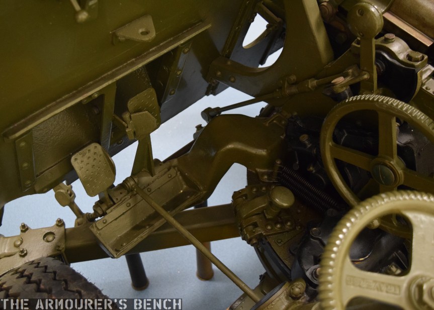
The gunlayer sat in a small seat mounted to the carriage and the loader knelt to the right of the breech. The gun was turned by a small traversing wheel operated by the gunlayer. In low gear one rotation of the wheel would turn the gun 3 degrees, in the higher gear (activated by the right foot pedal) one rotation traversed the gun 20 degrees. This meant the gun could be traversed the full 360 degrees with 18 rotations of the wheel. The right hand wheel controlled elevation of the barrel. The gun was fired by the gunlayer using the left foot pedal or two emergency firing levers if the pedal became inoperable. While the breech would typically open automatically ejecting the spent shell casing after firing a breech handle was also located on the right side of the breech.
The 2pdr’s foot pedals: traverse gear on the right, fire pedal on the left (Matthew Moss)
The gun could be brought in and out of action in under a minute, including removing or replacing the road wheels. The 2pdr could, however, be fired from its road wheels, this was described as ‘emergency action’. The wheels limited the traversing arc of the gun and turns greater than 14 degrees right or 10 degrees left had to be done by lifting the gun’s trail and turning it manually. While less stable and accurate the gun could be brought into action from being towed in less than 20 seconds.
In 1939, the British Expeditionary Force to France embarked with 509 2pdrs. During the 1940 Battle for France the 2pdr was found to be an adequate anti-tank gun. One problem identified with the 2pdr was that its armour shield, designed to protect the crew, gave it a quite high profile making it easier to spot and more difficult to conceal.
A view of the breech and down the barrel of a 2pdr (Matthew Moss)
During the retreat to Dunkirk and subsequent evacuation all of the guns brought to France were lost. 60% of Britain’s 2pdr Anti-Tank guns were left behind in France, just 333 guns which hadn’t accompanied the BEF remained. Many of the guns captured after the Dunkirk evacuations entered German service under the designation 4.0cm Pak 192(e).
As the thickness of enemy armour increased the 2pdr began to struggle. The German Panzer II had 1.2 inch thick frontal armour while the Panzer III more than doubled this to 2.8 inches. On paper at least the 2pdr, firing a APHV round, could penetrate up to 2.2 inches of armour at 500 yards (460m). But in reality the Panzer III was the last German tank the 2pdr could expect to engage with a decent chance of success. With the emergence of the later mark Panzer IV, with their 50mm or 2 inch thick frontal armour, they became much less effective. If not adequately concealed gun crews could expect to be engaged by AP and high explosive rounds from the Panzers at ranges outside their effective engagement range.
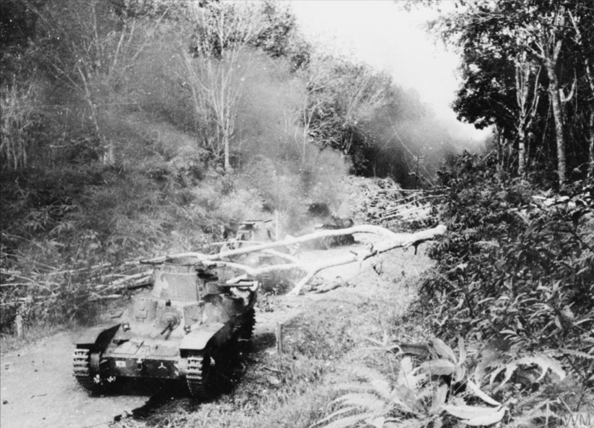
Despite this, however, the 2pdr proved to be a more than a match for Japanese tanks such as the Type 95 Ha-Go light tanks, which had armour less than an inch thick. At the Battle of Muar in Malaya, in January 1942, Australian 2pdrs, of the 13th Battery, 4th Anti-Tank Regiment, knocked out six, of possibly eight or nine, Japanese tanks as they attacked up a road near Bakri. Sgt. Charles Parsons, commander of one of the guns was awarded the Distinguished Conduct Medal (DCM). Interestingly. the Australians referred to the QF 2pdr AT Gun as the “Tank Attack 2pdr” apparently a designation common to Australian anti-tank weapons as they also called the PIAT the Projector, Infantry, Tank Attack.
The 2pdr remained capable of destroying heavier Japanese tanks too, the Type 97 Chi-Ha medium tank had at 1 inch thick front armour which the 2pdr could easily penetrate at ranges of over 1,500 yards.
Photograph of knocked out Japanese Type 95 tanks during the Battle of Muar (Imperial War Museum)
Lieutenant Ben Hackney of the Australian 2/29th Battalion described the engagement during the Battle of Muar:
“A couple [of tanks] attempted to turn and make a get-away but still those boys with the anti-tank guns were sending a stream of shells into them. At last they could not move forward any further and became as pill-boxes surrounded, sending fire in all directions; until one by one they were smashed, set on fire, and rendered useless and uninhabitable. There came then from the tanks sounds which resembled an Empire Day celebration as the ammunition within them burnt, and cracked with sharp bursts, and hissed, with every now and again a louder explosion as larger ammunition ignited.”
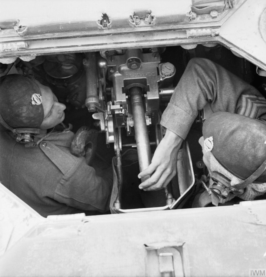
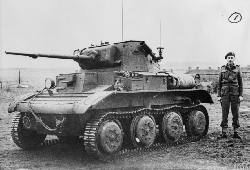
In addition to being used as a towed anti-tank gun the QF 2pdr was used in a wide range of light and cruiser tanks, it provided the main armament for the Matilda II, the MKVII Tetrach light tank, the first six Marks of the Valentine infantry tank, the MKI & MKII Crusaders, the Cruiser Marks I to IV, the Covenanter tanks and it was also used in the Australian cruiser tank, the AC1 Sentinel.
MKI AEC Armoured Car equipped with a 2pdr (Imperial War Museum)
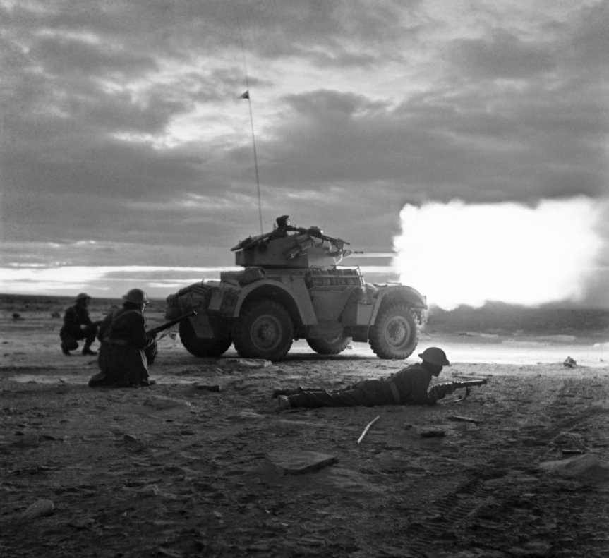
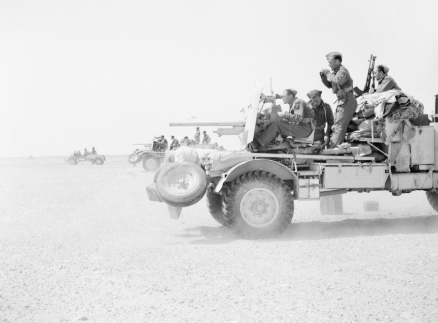
It was also widely used to arm armoured cars including the Daimler, the MKI AEC, the MKI Coventry and the Marmon-Herrington Armoured Car. In the desert it was also mounted and operated simply on the back of adapted trucks – known as Portees. Trucks built by Chevrolet, Ford or Morris were all pressed into service to create Portees. The 2pdr was deployed on its tripod on the truck bed with its wheels removed. In this setup the guns became highly mobile with the crew able to operate the gun from the truck moving in and out of action rapidly. They were widely used in North Africa with a number of medals including a Victoria Cross being awarded to men who manned them.
Second Lieutenant George Ward Gunn, J Battery, Royal Horse Artillery, was awarded a posthumous Victoria Cross for his actions in November 1941 during Operation Crusader. Gunn commanded a troop of four Portee 2pdrs which engaged a German counter attach, with all but one of his guns knocked out and the remaining gun’s crew killed and the truck on fire, Lieutenant Gunn manned the gun himself, engaging the enemy at 800 yards, he managed to destroy two Panzers before he was killed.
The example we are examining began its life as a Mark IX but was subsequently upgraded into a Mk XA, capable of using a Littlejohn adaptor. The Littlejohn adapter used the squeezebore principle, the device was about a footlong with a smooth tapered bore. With the adaptor fitted to the muzzle of the 2pdr the round would be compressed by the taper going from 40mm to 30mm in diameter. This had the effect of increasing muzzle velocity giving the round a flatter trajectory and more energy. An armour-piercing, composite non-rigid round with a tungsten core was used, designated the APSV (from ‘armour-piercing super velocity’). It had the effect of almost doubling the muzzle velocity of the APSV round when compared to the original 2pdr AP shell. The adaptor was invented by Czech designer, František Janeček, the founder of the JAWA motorcycle company. The Mk I Littlejohn device entered production in January 1943 and the Mk II was approved in May 1944.
While design of the 6pdr anti-tank gun, the 2pdr’s replacement, had been completed by 1938, production of the gun did not begin until 1942. Following the huge losses at Dunkirk and with invasion believed to be imminent the decision was taken to focus on the 2pdr gun as its production line was already established. They remained in service throughout the war equipping anti-tank batteries and armoured vehicles. Over 34,000 2pdr anti-tank guns were produced between 1936 and 1944, over 11,000 of these were deployed as anti-tank guns on carriages while the rest were used in various vehicles.
If you enjoyed the video and this article please consider supporting our work here.
Specifications:
Overall Length: 135.5in or 343cm
Weight: 1,800lbs or 816kg
Action: Semi-automatic, hydrospring recoil buffer
Calibre: 2pdr or 40×304mmR
Elevation: -13 / +15 degrees
Traverse: 360 degrees
Rate of fire: 20 rounds per minute
Bibliography:
Anti-Tank Weapons, T. Gander, (2000)
British Anti-Tank Artillery 1939-45, C. Henry (2004)
‘British equipment Losses at Dunkirk and the Post-Dunkirk Situation’, WWII Equipment.com, D. Boyd, (source)
2 Pounder Anti-Tank, Royal Army Ordnance Corps (RAOC) training film, via AWM, (source)
Here’s Vic’s video on the XM148, check out Matt’s article below:
There have been attempts to fire grenades from the infantryman’s weapon since the 17th century. Up until the 1960s these almost entirely involved muzzle attachments or grenades which could be fired off the end of a rifle’s barrel. In May 1963, the US military called for a new ‘underslung’ grenade launcher to complement the AR-15/M16, then in early testing. The grenade launcher program had its roots in the ultimately unsuccessful Special Purpose Individual Weapon (SPIW) program which had begun in 1952.
While a series of designs were developed by various manufacturers and designers, May 1964 saw Colt unveil the CGL-4. The Colt was tested against designs from Springfield Armory and Ford, a design from AAI was promising but it was not able to chamber the 40x46mm rounds used by the M79 and was rejected. The US military sought munitions commonality between the M79, already in service, and the new rifle-mounted grenade launcher.
Left side view of the XM148’s bulky tangent sight (Vic Tuff)
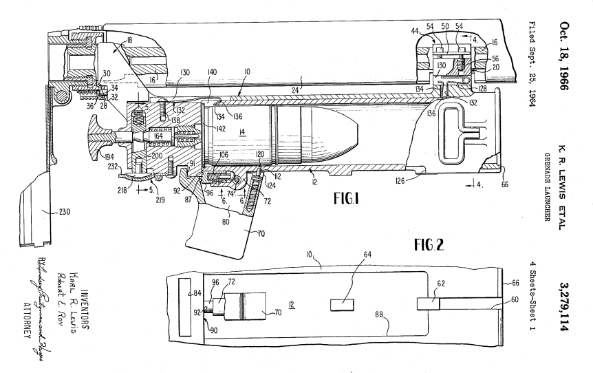
In March 1965, the CGL-4 was chosen for further testing and a contract for 30 launchers was signed. The CGL-4 was reportedly developed by Karl Lewis and Robert E. Roy in just 48 days. However, the design was complex. To load the barrel housing slid forward allowing a grenade to be placed in the breech, the weapon was then cocked and a long trigger, which projected back towards the rifle’s trigger guard, could be pulled to fire the weapon.
Karl Lewis & Robert E. Roy’s patent for the Colt CGL-4 (US Patent Office)
Despite some problems with barrel housings cracking an order for 10,500 of the new launchers, now designated the XM148, was placed in January 1966. Production capacity issues and problems with the launcher’s sight lead to production delays and it wasn’t until December 1966, that the first shipment of 1,764 launchers arrived in Vietnam for field testing.
Right side view of the XM148’s trigger, cocking mechanism and pistol grip (Vic Tuff)
Initial reports from the field were promising with troops praising the “tactical advantage of both the point fire and area fire system” concept. The XM148 was well received by the SEALs and the Australian SAS. The armourers of the Australian SAS, deployed to Vietnam with the 1st Australian Task Force, were also hard at work attaching XM148s to L1A1 rifles. Removing the L1A1′s handguard and attaching the XM148 to the rifle’s barrel.
Field testing was carried out by 12 units from six different divisions which were operating in various parts of Vietnam. This gave a wide variety of terrains and yielded some interesting results. In general it was found that the XM148 decreased rate and quantity of the grenadier’s fire, it slowed his reaction times when firing at a target, it hampered his movement in dense vegetation and also meant the grenadier had to spend longer caring for his weapon.
XM148 with breech open (Vic Tuff)
It was noted that the sight mount which was overly complex and prone to snagging on brush and kit, it was also felt that too much force was needed to cock the XM148 (around 30 lbs) and the trigger mechanism was felt to be overly complex and difficult to repair and disassemble. One safety concern was the XM148′s long trigger bar, which could snag and launch a round – not ideal for special forces patrols infiltrating through thick bush. Problems with the launcher’s quadrant sights also continued causing deflection errors out at longer ranges. The bulkiness of the sights exasperated these problems as when they were knocked the XM148′s zero could be effected. The XM148 also precluded the use of a bayonet as when fired it would blow the bayonet off the muzzle. Overall, troops felt the XM148 was too fragile and complex for use in the field.
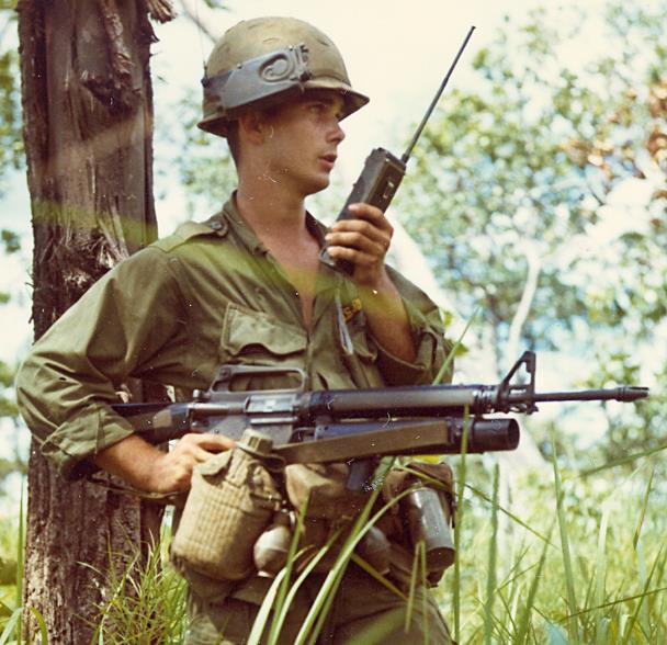
SP4 Willey firing an M16A1 mounted with a Colt XM148 c. 1967 (US National Archives)
At least one unit found use for the launchers, the 1st Cavalry Division (Airmobile)’s Operational Report for Quarterly Period Ending 31 October 1967, noted that the XM148
“proved unsatisfactory in infantry units due to its lack of durability; consequently, USARV directed that they be turned in. However, 1/9 Cav has devised a method of mounting the launcher coaxially on the M60C machine gun used by scout observers on OH-13 scout helicopters. Durability in this environment is
not a problem since the weapon deos not receive the rough handling it did in the hands of ground troops. Firepower on scout helicopters is significantly increased. Fifty-two XM148s have been retained for use by 1/9 CAV.”
Finally, despite Colt’s efforts to rectify the growing list of problems the Army Concept Team In Vietnam deemed the XM148 unsatisfactory for deployment in Vietnam and recommended they be removed from service and a new improved launcher be developed. This was a massive blow to Colt who had already manufactured 27,400 XM148s. Many of these were already in Vietnam.
The US Army launched the Grenade Launcher Attachment Development (GLAD) program in the summer of 1967. A large number of manufacturers submitted designs including Colt, who offered the improved Henry Into-designed CGL-5. The Army turned down Colt’s offer of 20 free improved launchers and rejected the CGL-5 outright. The GLAD program saw the resurgence of the earlier AAI design, designated the XM203, this simple design, now chambering the 40x46mm shell, was eventually selected in August 1968. Ironically, as AAI was predominantly a research and development company and after an initial run of 10,000 made by AAI, Colt was subsequently awarded the contract to manufacture the M203 from 1971 onwards.
Harold Into’s patent for the product improved CGL-5 (US Patent Office)
While the XM148 proved to be a failure it played an important role in proving the operational viability of the rifle mounted grenade launcher system. The muzzle-launched rifle grenade is all but obsolete, superseded by the under-slung grenade launcher.
If you enjoyed the video and this article please consider supporting our work here.
Specifications:
Length: 16.5 inches
Weight: ~3lbs
Calibre: 40x46mm
Action: single shot, striker-fired single action
Capacity: 1
Rate of Fire: ~4 rpm
In early 1865, in the wake of the Danish-Prussian War which had shown how effective breechloaders could be, Britain’s Board of Ordnance began to explore retrofitting Britain’s muzzle-loading Pattern 1853 Enfield Rifle Muskets with a breech-loading cartridge conversion. Along with this interim solution the Ordnance Department also began the search for a breech-loading rifle designed from the ground up. Dozens of designs were examined from engineers and gunsmiths from across Britain, Europe, and the United States. One of these came from Johann von der Poppenburg, a Birmingham based engineer. Poppenburg’s rifle was tested along with 24 others during the initial phase of testing. The Ordnance Department’s Breech-Loading Rifle Committee were largely unimpressed by the rifles submitted and selected only four to progress, Poppenburg’s design was not included.
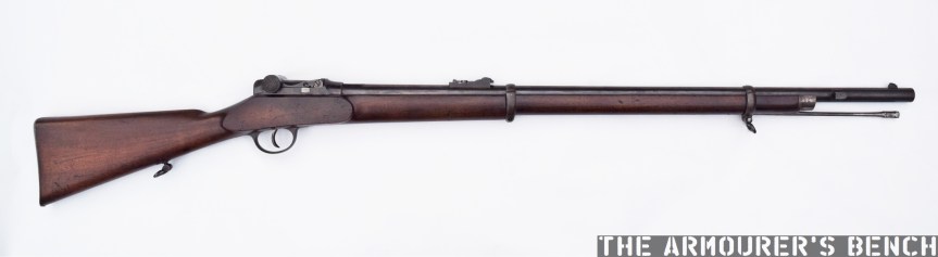
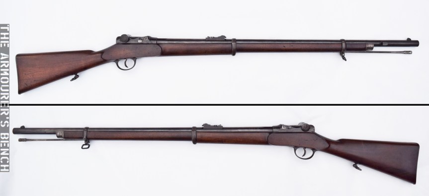
An 1866 Benson-Poppenburg Rifle (Matthew Moss)
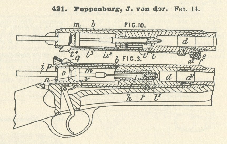
Poppenburg patented his first breech-loading design in February 1865 (#421) with an American patent following in October (US #50,670). It was this system which was first submitted to the trials, the rifle while described as ‘Poppenburg’s principle’ was made or at least submitted by Messers. Benson and Co., also of Birmingham.
Poppenburg’s patent describes a system that could be loaded with either loose powder and a projectile – with a percussion cap igniting the charge held in the ‘charge-chamber’ or with a paper cartridge which was detonated when pierced by a needle. It was the latter, more modern, option which was chosen for submission to the British trials.
The submitted design used a needle fire action, which ignited a paper cartridge by piercing through the paper and powder to ignite a copper cap in the base of the projectile. Poppenburg patented this cartridge design was on 3rd April 1865 (#932), it lapsed three years later and became void in April 1868. The action was hinged to the right, with a hollow breech chamber swinging out to allow a cartridge to be loaded into it. The estimated unit cost to produce these rifles, for quantities over 5,000 rifles, was £3 each. The needle fire action and hinged breech proved “too complicated, and liable to accident for a military arm” according to the Trials report.
Poppenburg’s needle fire breechloader, patented February 1865 (courtesy of Research Press)
Interestingly, in October 1866 Poppenburg also patented specific system for a breech-loading conversion (#2580). The system used a vertically hinged breech block which locked using a rack and pinion system attached to a lever. It does not appear that this system was tested by the Trials Committee. This action may have been developed following the failure of his more complex action and the adoption of the brass-cased .577 round. This patent lapsed and became void in October 1869.
The October 1866 patent (#2580), appears to be the last patented solely under Poppenburg’s name. Subsequently patents were granted jointly between Poppenburg and John Solomons Benson. This may have been due to the cost of applying for and maintaining patents, which in the 1860s could cost over £45 for three years of protection. Today that’s the equivalent of over £5,000 or nearly $7,000. Both Benson and Poppenburg were based in Birmingham, Britain’s leading centre for small arms manufacturing at the time. In a patent notice, dated 22nd December 1866 (#3382), Benson is listed as a merchant while Poppenburg is described as a mechanical engineer. It may be that Benson provided the financial backing for Poppenburg’s breech-loading system, this was an arrangement that was common at the time.
left and right profiles of the 1866 Benson-Poppenburg (Matthew Moss)
In 1866-7 Benson and Poppenburg submitted a number of rifles for testing in the Prize Competition launched by the War Office to find a new breech-loading rifle. The system submitted was radically different to Poppenburg’s earlier needle fire designs which used hinged breeches. The patent for the new system was granted jointly to Benson and Poppenburg on the 22nd December 1866 (#3382).
Poppenburg’s third breechloading design, co-patented with John Benson, patented December 1866 (courtesy of Research Press)
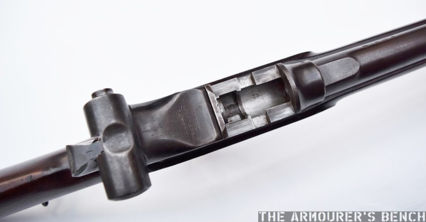
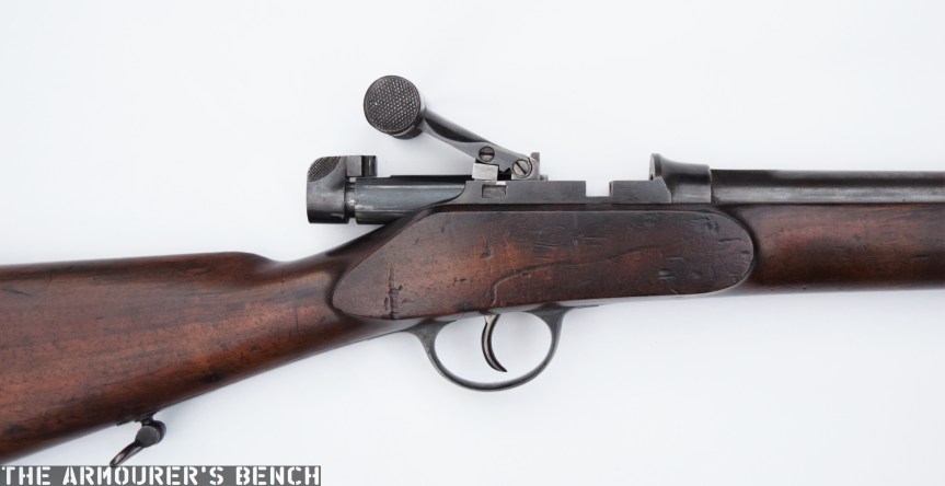
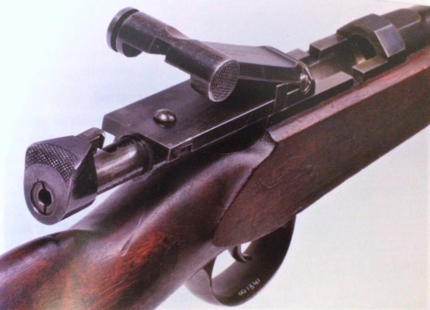
Benson and Poppenburg’s new rifle had a breech which opened horizontally with a ‘tubular breech-block’ which slid to the rear when a hinged lever was liftedand pulled backwards. To open the breech the rifleman first depressed a small catch on the left side of the breech cover, once depressed the breech block could then be pulled back by the hinged lever. This movement also actuated the rifle’s T-shaped semi-circle extractor allowing the rifleman to remove the spent case. A new cartridge could then be loaded and the breech closed and the striker was then pushed forward with the thumb to cock the weapon. Once the hinged lever was pushed forwards again the breech block moved forward, closing the action, and locked with a pair of lugs cut into the receiver (described as the ‘breech-shoe’ in the patent) and at the rear by the catch.
The Benson-Poppenburg with its breech open, note the t-shaped semi-circular extractor (Matthew Moss)
Depressing the breech release button with the striker cocked will de-cock the action and in theory allow a round to be carried in the chamber. The example pictured in the accompanying photographs may be a slightly more refined version of the rifle submitted as it differs from another rifle, said to be a trials gun, which more closely resembles the December 1866 patent.
Breech Closed (Matthew Moss)
Breech Open (Matthew Moss)
The rifle with its breech closed (left) and open (right)
At least four rifles (with some differences in design between them) were provided for testing, the War Office’s April 1868 Report on Breech Loading Arms found that three of the rifles submitted were shorter than the required length while a fourth was too long – with the maximum overall length allowed being 51 inches. Examples of both full-length rifles, with 32 inch barrels, and carbine models with 23½ inch barrels exist (both of these lengths are significantly shorter than the Snider-Enfield’s barrel length). The trials rifles appear to have been sighted out to 1,100 yards and were chambered in a .577 calibre cartridge (probably the Boxer cartridge selected officially in 1866). At least two probable trials example were also chambered in a .450 cartridge. From a survey of the remaining examples it seems that the serial numbers for the rifles range up to at least 239.
Right side view of the rifle with its breech open, note the breech lever projecting upwards and the breech block and cocking assembly back (Matthew Moss)
The Benson-Poppenburg was unsuccessful during the trials, being rejected from both the Prize Competition and the Breech Action Selection Trials. With the Committee’s report stating that despite the rifles having “several good ideas embodied in their breech action”, they “appear to have been hastily manufactured and the inventions are as yet in an incomplete state”. The specific reasons given for this were that the rifles were of unsatisfactory overall lengths. It seems they were submitted in a rush, in an ‘incomplete state’, with the report also noting that the extractors on two of the rifles submitted destroyed cartridges during extraction, probably ripping the base from the case.
The Committee’s report explained that its rejection from the separate Breech Action Selection Trials was due to issues: “if dirt or sand enters the shoe of this rifle it causes misfires, and even prevents the bolt from entering the aperture in the block.” They also noted that “The working of the breech mechanism is slow.”
The British Army’s extensive trials eventually resulted in the selection of Jacob Snider’s system, adopted in April 1866 to convert existing Pattern 1853s and the selection of Friedrich von Martini’s action and Alexander Henry’s barrel, which when combined as the Martini-Henry was formerly adopted in March 1871.
Addendum:
Mathieu Willemsen, curator of the Netherlands’ Military Museum, was kind enough to share some information about The Dutch Army’s trials with the Poppenburg in 1868. The Dutch trialled a version similar to that tested by the British but chambered in 11x42mmR. The rifle’s action has a more angled external appearance than the example we have examined but works along the same principle.
1868 Benson-Poppenburg trials rifle, note the longer breech lever (courtesy of Mathieu Willemsen)
The rifle was found to be rapid firing but suffered from some issues with fouling and failed a pressure test. Later testing with a smaller calibre round was also carried out but the rifle was not adopted. We hope to have a chance in the future to examine a Dutch trials rifle for comparison.
If you enjoyed the video and this article please consider supporting our work here.
Bibliography:
Treatise on the British Military Martini, I. Skennerton, (1995)
Reports of a Special Committee on Breech-Loading Rifles (1869)
Abridgements of the Specifications Relating to Fire-Arms and Other Weapons, Ammunition, and Accoutrements, Commissioners of Patents, (1870)
‘Poppenburg’s Projectiles’, Newton’s London Journal of Arts and Sciences, (January, 1866)
Experiment and Trial, M. Willemsen (2012)
Various British Patents:
‘Breech Actions, Hinged-Chamber’, J. von der Poppenburg, UK Patent #421, 14th Feb. 1865
‘Projectiles and cartridges for central-fire breech-loading fire-arms and ordnance’, J. von der Poppenburg, UK Patent #932, 3rd Apr. 1865
‘Breech Actions, Hinged Breech-Block’, J. von der Poppenburg , UK Patent #2580, 6th Oct. 1866
‘Breech Actions, Sliding Breech-Block’, J.S. Benson & J. von der Poppenburg, UK Patnet #3382, 22nd Dec. 1866
‘Breech Actions, Hinged Breech-Block’, J.S. Benson & J. von der Poppenburg, UK Patent #1950, 15th June, 1868
‘Improvement in breech-loading fire-arms’, J. von der Poppenburg, US Patent #50670, 24th Oct. 1865, (source)
Special thanks to our friends at the Hayes Collection for letting us examine their rifle, and thanks to David Minshall over at the Research Press for his help researching Poppenburg’s numerous patents.