In the first part of Vic’s special episode on the AR-10 we brought you a remastered version of the fascinating 1958 ArmaLite/Fairchild promotional sales film made for ArmaLite salesmen, like Sam Cummings and Jacques Michault, to show to prospective buyers of the new rifle. Back in the 1990s Vic was lucky enough to scan Michault’s copy the film and has recently remastered with better image quality.
Below you can find the video, time stamped to begin at the promotional film (although I highly recommend you watch the entire video for Vic’s introduction to the early history of the AR-10).
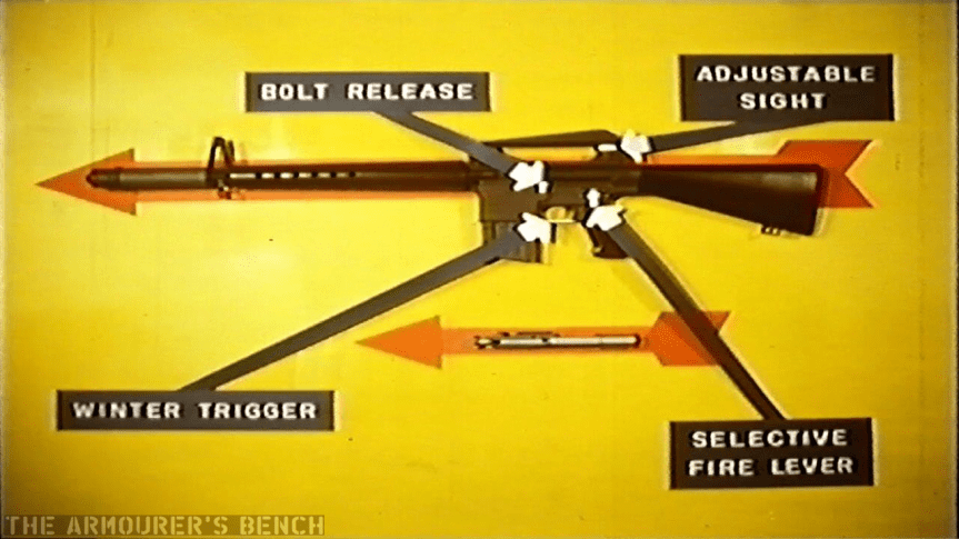
Lets break the video down, with the help of some screen captures. The film opens with a rifleman emerging from the sea, firing as he advances. The film then explains Fairchild’s background and beings to explain the features of the rifle.
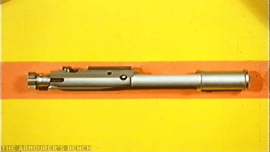
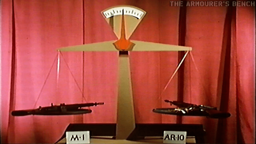
Arrows point out some of the AR-10s controlsA close up of the rifle’s bolt and carrierA set of scales is used to demonstrate how the AR-10 (plus 50 rounds) is equal to an M1 Garand
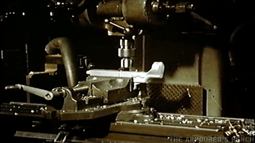
The film then shows several shots of the rifle’s lower receiver being milled.
The milling of the rifle’s aluminium-alloy forged receiver
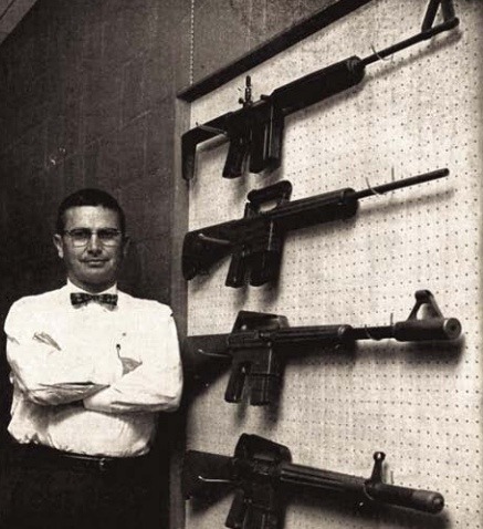
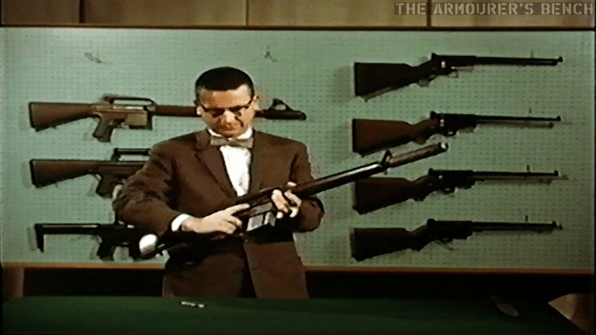
None other than the rifle’s designer himself, Eugene Stoner, then takes an AR-10 from a wall display and proceeds to completely disassemble it.
Stoner standing in front of a display board holding three AR-10 prototypes and AR-5s and an AR-7 survival rifle
Stoner completely strips the rifle, its muzzle device and its magazine before Charles Dorchester, ArmaLite’s production manager, demonstrating the rifle’s operation and subjects it to sub-zero temperatures and once again firing the rifle.
Chuck Dorchester submerges he rifle in what appears to be liquid nitrogen
Dorchester again test fires the rifle
The film then shows the rifle being used in a variety of roles:
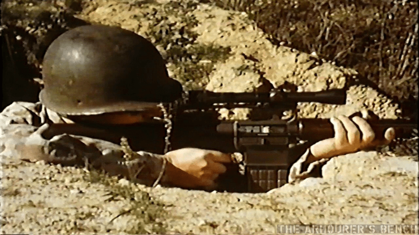
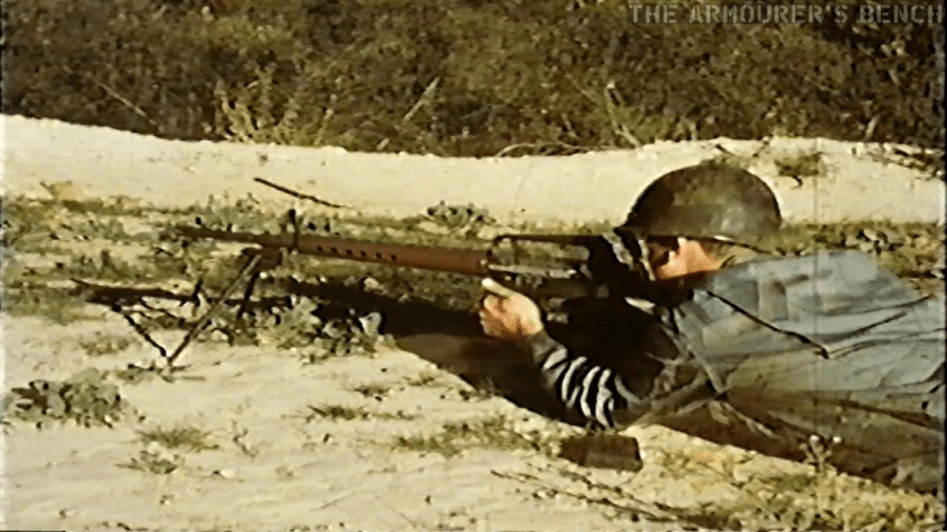
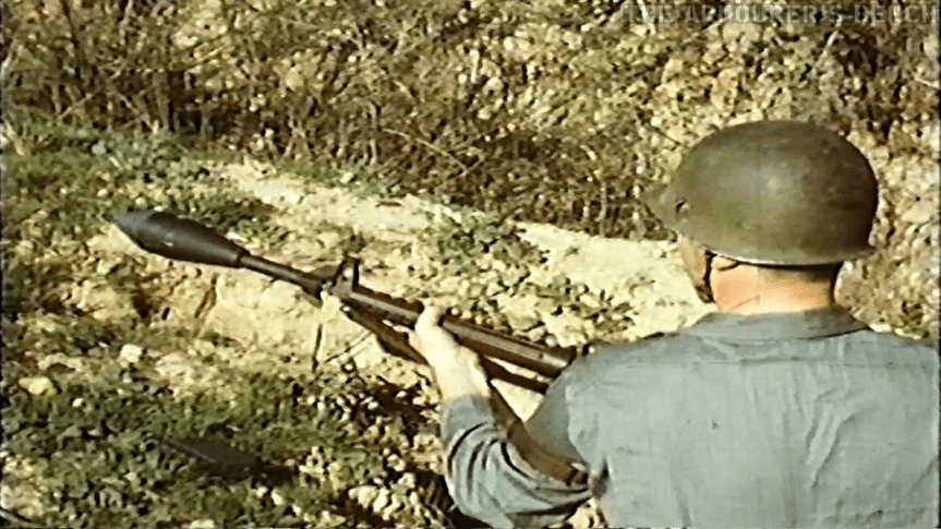
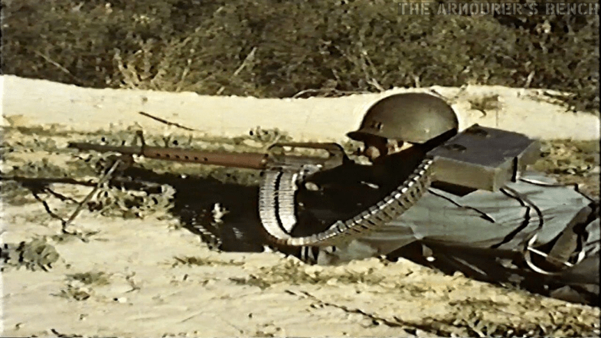
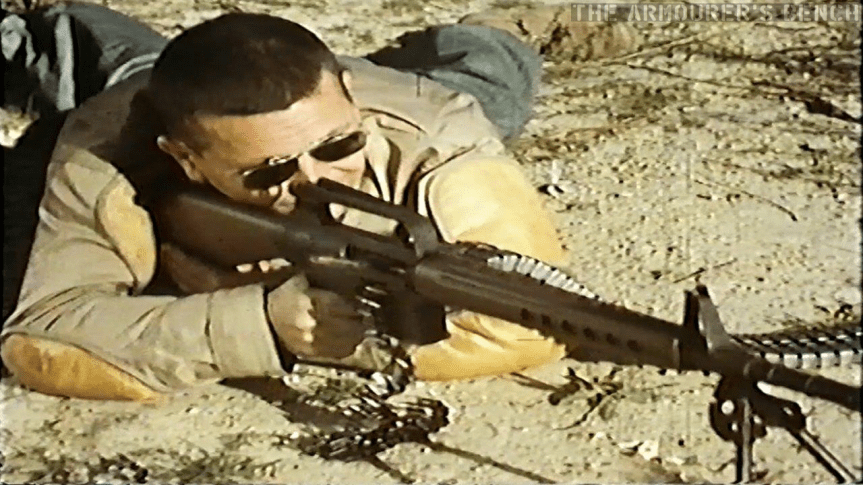
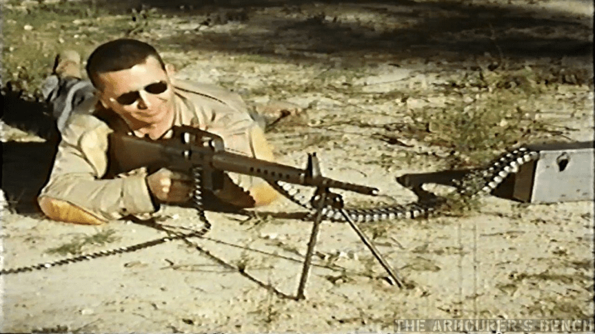
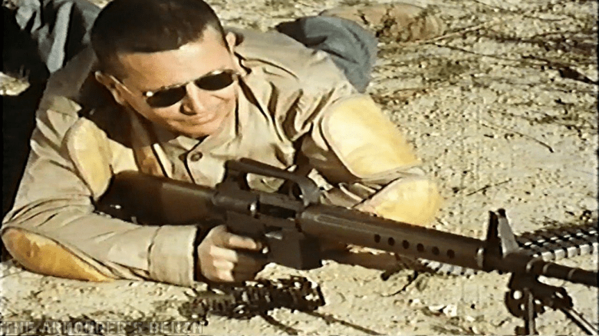
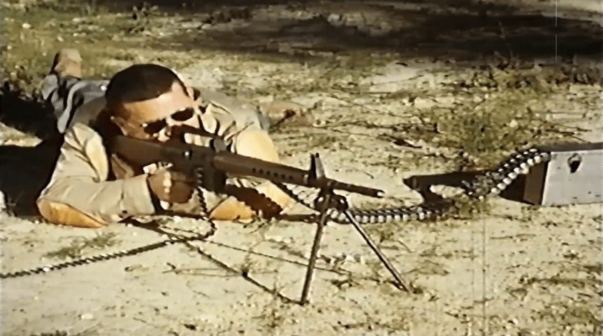
AR-10 being fired with a scope mounted to the carrying handleThe AR-10 being fired from a bi-pod in the light support role, feeding from 20-round magazines, the AR-10 LMG could easily be switched between magazine and belt feeding by removing the belt feed assemblyAn ENERGA rifle grenade being fired from the AR-10, the US Army had adopted the ENERGA as the M28 rifle grenade in 1950.
Stoner then covers the rifle with sand before running five magazines through the rifle in quick succession to demonstrate reliability:
This slideshow requires JavaScript.
The rifle is then submerged in mud (with its dust cover closed) and demonstrated again.
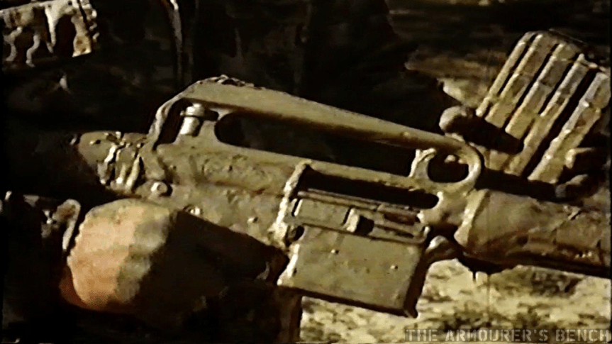
AR-10 covered in mud
The film then shows how simple field stripping and cleaning is before Stoner demonstrates the belt-fed variant of the rifle:
A rifleman demonstrates the AR-10 in its belt-fed configuration, changing position several times before switching to feeding from magazines. Note also the ‘backpack’ belt box and controlled chute/feedwayStoner firing the belt-fed AR-10Stoner with a happy grin on his face before opening up with the AR-10,Note the bolt link port in the lower receiver
Don’t forget to check out the full episode and the accompanying blog here!
If you enjoyed the video and this article please consider supporting our work here.
In this first part of a TAB special episode examining the history of the ArmaLite AR-10 Vic discusses the early origins, history and development of the now legendary 7.62x51mm rifle. At the heart of this episode is a remastered version (certainly the best currently available online) of the c.1958 ArmaLite/Fairchild promotional film that features Eugene Stoner and shows many of the early ‘Hollywood’ Armalites in action! The first part of this special documentary concludes with Vic examining a Hollywood-made AR-10B (the last iteration of the US-made AR-10s).
Part two of the episode can be found here and includes an overview of almost every Artillerie Inrichtingen (A.I.)-made model of AR-10, including the Cuban, Sudanese and Portuguese variants.
Armalite & the AR-10’s Early History
Much has been written about the AR-10, Eugene Stoner and the genesis of the AR-15’s parent rifle. It’s a design which owes much to many: Stoner, George Sullivan, Melvin Johnson and later the engineers at Artillerie Inrichtingen.
Photographs taken during Springfield Armory’s evaluation of the AR-10B (source)
ArmaLite, formed by George Sullivan with the help of Richard Boutelle, President of the Fairchild Engine and Aircraft Corporation, began work on the first AR-10 prototypes in 1955. Designed by Eugene Stoner, using his patented direct gas impingement system. Stoner patented this system in 1956, with the patent being granted in September 1960 (US #2,951,424).
Stoner pictured with some of the Hollywood AR-10 prototypes for a 1958 article in Guns magazine (source)
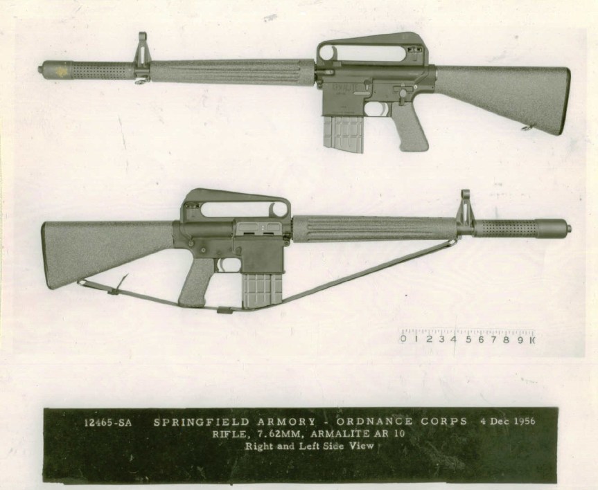
The AR-10 had an aluminium-alloy forged receiver, an in-line stock, polymer furniture and chrome-lined steel parts. While conventional steel barrels were the norm an ill-fated attempt to use an aluminium/steel composite barrel during US Army evaluations proved disastrous when the steel inner parted from the aluminium outer and caused the barrel to burst. As a result of these weight saving efforts the rifle weighed just ~3.4kgs/7.5lbs unloaded. The Armalite AR-10 had a side mounted gas tube, a top mounted charging handle and fed from 20-round box magazines. One of the most interesting features was the large aluminium muzzle device, fitted to some ArmaLite-made Rifles, which reduced sound and flash.
In 1957, ArmaLite sold the AR-10 manufacturing rights to the Dutch small arms manufacturer Artillerie Inrichtingen, while US manufacture was licensed by Colt in February 1959. With minimal financial returns Fairchild sold their interests in ArmaLite in 1962.
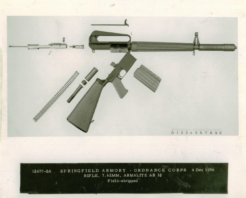
A Springfield Armory file photograph of the AR-10B disassembled, taken during evaluations in 1956 (source)
Featured in the first part of Vic’s special episode on the AR-10 is an original Armalite/Fairchild promotional film, originally filmed in 16mm, that dates from around 1958. While a version of this film has been shared online for a number of years it is grainy, washed out and of relatively low audio quality. Vic reproduced the very rare promotional sales film in the 1990s onto VHS (a process he explains in the video). He has managed to take an original VHS copy and digitally remaster it to regain some of the original’s clarity and detail.
A still from Vic’s remastered 1958 promo film showing Stoner firing the belt-fed variant of the AR-10 (source)
The promotional film was originally used by salesmen to showcase the AR-10 to potential clients and features Hollywood-produced guns. Both Stoner and Charles Dorchester (ArmaLite’s production manager) are seen in the film demonstrating the AR-10. The rifle’s action, function and controls are explained and various variants, including rifle and light machine gun, are demonstrated. The demonstration segment included a sub-zero test, covering in sand and much and Stoner himself dumping 5 magazine’s through the rifle in quick succession. The promotional film concluded with demonstrations of firing rifle grenades and a belt-fed AR-10.
Vic concludes the first part of the AR-10 overview episode with an examination of an AR-10B rifle held by the Netherlands’ Nationaal Militair Museum. In the second part of the episode Vic will look at nearly a dozen AR-10 variants made by Artillerie Inrichtingen (A.I.) between 1957 and 1961.
In 1968 Heckler & Koch launched the HK33, chambered in 5.56x45mm, to compete with Colt’s AR-15/M16. The HK33, and later HK53, used the same roller-delayed blowback action developed for the G3 in the mid 1950s. However, few major contracts were forthcoming with the German military opting to continue using the 7.62x51mm G3.
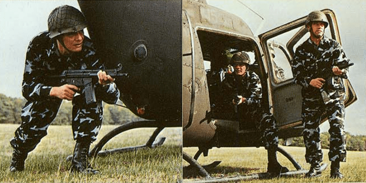
Due to the modularity of the HK33′s design users could replace the butt of the standard rifle with a collapsible telescopic metal stock. H&K also subsequently designed a carbine version of the full-length HK33, the HK33K with a telescopic metal stock and 12.7 inch barrel. In the mid-1970s H&K began development an even shorter version. The result was essentially an intermediate calibre submachine gun similar to the Colt Commando and the Soviet AKS-74U. H&K designated this new weapon the HK53, it used the same telescopic stock as the HK33K and MP5 and a cut down 11 inch barrel, the HK53 also utilised a polymer forearm similar to the MP5s.
Contemporary promotional photos dating from 1985 (source)
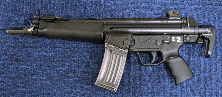
Like the HK33, the HK53 fed from 25, 30 or 40 round box magazines. The weapon weighed just over 3kg (7lb), almost a 1 kg less than its parent rifle the HK33. Unlike the HK33, the HK53 has a four prong flash hider. A number of police forces and militaries adopted the HK53 for a variety of roles. Special forces units around the world including the British SAS, Royal Military Police Close Protection Unit and Royal Marines, designated the L101A1 in British service, who typically used it during close protection duties and operations involving close quarter battle.
Contemporary promotional photo dating from 1985 (source)
As shown in various MoD Equipment Failure Reports dating from the early 1990s the HK53’s in British service suffered from repeated damage and failure of the carbines’ locking rollers. This issue arose when using a number of different ammunition types including brass cased blank ammunition (H&K recommend the use of their proprietary blank cartridges). Following a meeting between the Army Technical Support Agency’s Directorate of Engineering and H&K a new design for the locking pieces were developed. These changes “increased the roll of blowback force during the unlocking phase… in turn this will reduce the mean energy of the recoiling mass of breech block and carrier” this was intended to reduce bolt bounce. The Royal Military Police Close Protection Unit’s L101A1’s were also fitted with a new two stage buffer within a fixed stock. In British service the L101 was replaced by the L22A2 carbine and the L119A1 (C8 Carbine).
HK53, stock collapsed, (Matthew Moss)
Due to its short length the HK53 also found itself pressed into the port-firing weapon role. Designated the HK53 MICV in this role the foregrip and stock was removed and a specially designed endcap and a spent case bag could be attachment. During its service life the HK53 went through a series of changes to furniture mouldings, buttstock types and fire selector options. It remained in production into the early 2000s, when Heckler & Koch replaced the HK33 and HK53 with the G36 and G36K.
If you enjoyed the video and this article please consider supporting our work here.
Itemised list of L101A1’s which suffered damaged locking rollers, MoD Equipment Failure Report, 15 Nov. 1994, (via Small Arms Review Reference Library)
The 1960s and 70s saw Chile was racked by political turmoil with a military junta, led by General Augusto Pinochet, taking control in September 1973. Pinochet’s Junta took control of the country via a bloody coup, overthrowing President Salvador Allende, and as a result all export of small arms from Britain to Chile ceased. In the early 1970s, before the coup d’etat, The records of the Sterling Armaments Company show Chile purchased an example of the company’s Mk4 submachine guns and no less than 101 suppressed Mk5 Sterling-Patchetts.
With the import of small arms from the UK and other countries banned by an embargo Chile’s government were eager to increase their self-sufficiency. As a result in the mid-1970s the state-owned firearms manufacturer Fábricas y Maestranzas del Ejército (FAMAE) experimented with copying the Sterling Mk4 in an effort to minimise development costs.
Left-side view of the PAF with its stock extented (Matthew Moss)
The resulting 9x19mm submachine gun was dubbed the PAF or ‘Pistola Ametralladora FAMAE’. It took the basic Sterling design and simplified it. The PAF lacks the Mk4’s perforated barrel jacket and instead has an exposed barrel, tipped with a rudimentary spoon-shaped compensator. It also lacked the Sterling’s folding stock, instead it had a simple collapsing stock. As a result, the disassembly catch has been moved 90-degrees to the left side of the receiver.
Right-side view of the PAF (Matthew Moss)
Like the original, the Chilean copy retained the dirt-clearing grooves cut into the weapon’s breech block. The PAF’s plastic charging handle and butt stock shape are reminiscent of the Heckler & Koch MP5 – although much cheaper feeling in quality. The profile of the PAF’s pistol grip is slightly different but the weapon still fed from standard 34-round Sterling magazines. Interestingly, unlike the Sterling’s screwed-in-place barrel, the PAF’s was held in place by a machined barrel nut – in terms of production this is a much simpler system, no doubt borrowed from the Uzi.
left-side view of the PAF with stock collapsed (Matthew Moss)
Mag housing, front sight hood and barrel nut (Matthew Moss)
Magazine Housing (Matthew Moss)
The Chilean copy weighs significantly less than the British original, 2.5kg (5.5 lbs) and reportedly has a much higher 800 rounds-per-minute rate of fire. In general the PAF looks much like Sterling’s own later Para Pistol model, the Mk7.
Some sources suggest that only a small number of toolroom prototypes were made, although the relatively high serial number, #00748, of the example we looked at may indicate a limited production run may have been produced. It is clear, however, that the PAF did not go into general production. Instead, FAMAE later focused on weapons derived from Swiss small arms including the SIG SG 510 and SIG SG 540, and the SAF submachine gun introduced in the 1990s.
Note: The PAF was the last weapon we filmed during this particular research trip and we did not have time to film or photograph the PAF’s internals (we filmed a lot of videos that day and were pressed for time). Rest assured if and when we get the opportunity we will update this article with photographs of the weapon disassembled!
If you enjoyed the video and this article please consider supporting our work here.
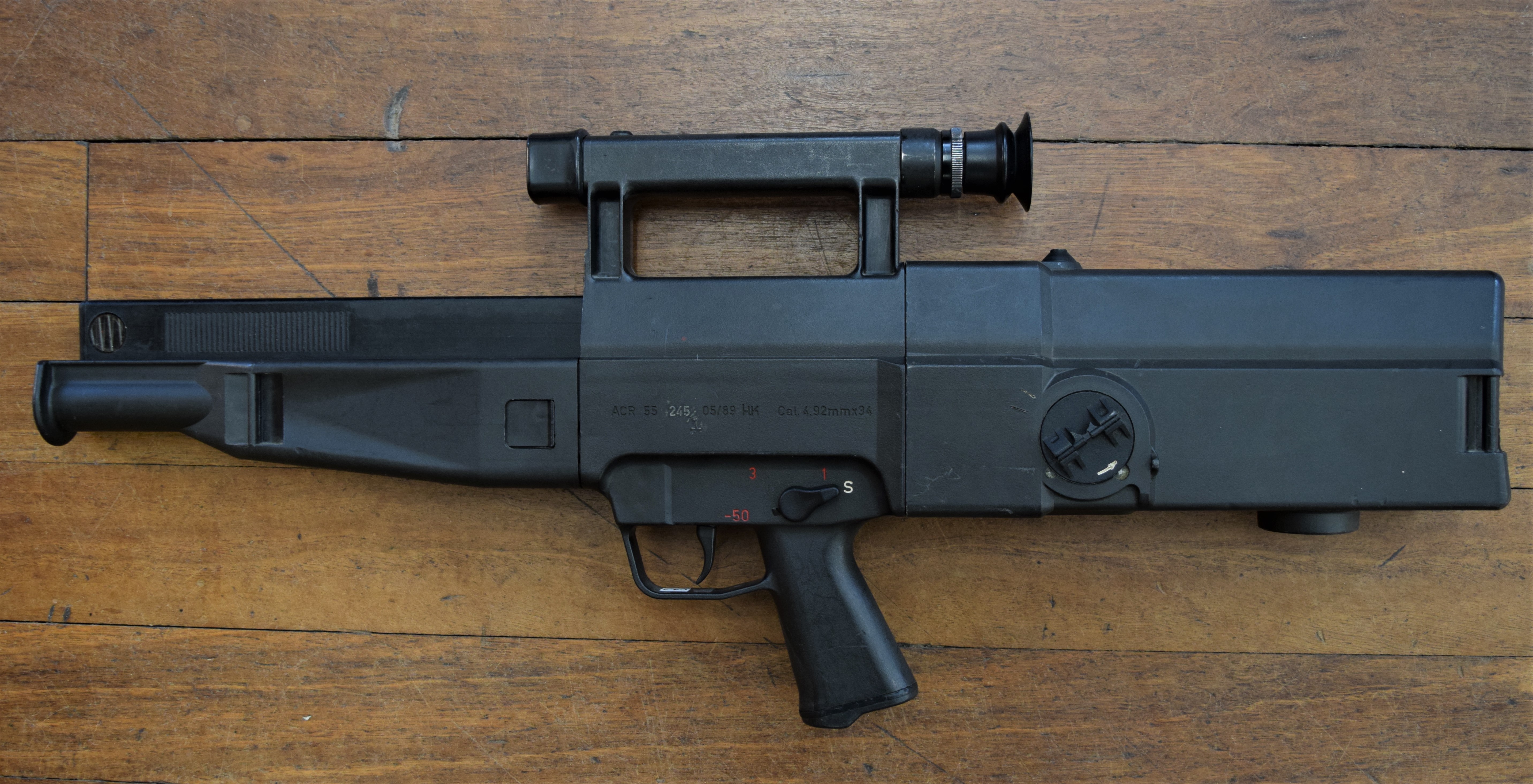
Vic kicks off his series looking at the US Army’s ACR trials rifleswith a look at, not one but two versions of, Heckler & Koch’s advanced caseless ammunition assault rifle – the G11. This video is an introductory overview, we’ll be delving into the G11’s insanely intricate and wonderfully complex action in later videos!
HK ACR 4.92x34mm G11 (Matthew Moss)
There are few experimental weapons that have cultivated myth and reputation like Heckler & Koch’s G11. The product of decades of research and development into what was hoped would be the next evolutionary step in small arms design. The G11 was Germany’s attempt to combine advanced caseless ammunition with a weapon system which could increase the average infantryman’s hit probability. The G11’s action has three distinct modes of fire and uses a complex action and buffer/recoil system to achieve a high rate of controlled fire.
The program began in the late 1960s as part of a NATO initiative, however, it became a primarily Bundeswehr project and over two decades the design evolved substantially. The project sought to increase the hit probability of the individual infantryman. Heckler & Koch’s approach to this problem was the most radical. Working with Hensoldt to develop an integrated optical sight and with Dynamit-Nobel to create a new kind of ammunition.
Numerous studies and theoretical designs were worked up but by the mid-1970s the base design of what would become the G11 was cemented. The design team included Gunter Kastner, Dieter Ketterer, Tilo Moller and Ernst Wossner – all of whom are credited in H&K’s 1976 patent protecting the G11’s rotary action.
The G11 went through dozens of iterations throughout the 1970s and 80s, with the first firing prototypes ready by 1974. Both the design and the ammunition also went through a number of changes.
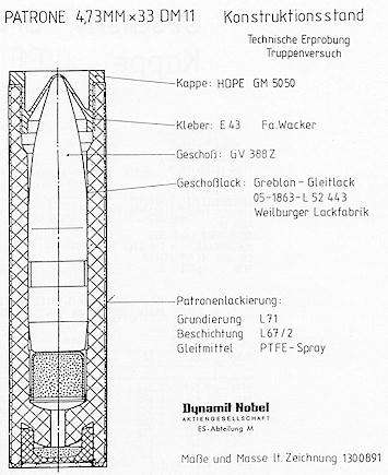
Diagram showing the composition of the G11’s caseless ammunition (source)
The revolutionary ammunition was developed by Dynamit-Nobel AG.
The 4.73x33mm round which was finalised comprised of a solid propellant material body which encased a primer, booster, projectile and a plastic nose cap. Dynamit-Nobel developed the High Ignition Temperature Propellant (HITP) in an effort to prevent accidental ignition (cook-off) of the ammunition’s outer propellant body.
The G11 fed from 45 or 50-round horizontal, single stack box magazines which fed rounds into the action at 90-degrees. The rounds were then rotated into alignment with the breech by the rifle’s action.
The rectangular shape of the Dynamit-Nobel ammunition was more efficient and better suited to storage than conventional circular rounds. The positioning of the magazine along the top of the weapon, parallel to the barrel, also in theory helped minimise the rifle’s profile and reduce encumbrance for the soldier equipped with the weapon.
The G11 is a gas-operated weapon with gas being tapped from the barrel, to cycle the rifle’s cylinder drive system, which rotated the breech through a series of cams and gears. At the heart of the G11 is a complex rotary action. Rotating actions themselves are not a new concept with the earliest dating back to the 17th century, such as the Lorenzoni system.
The G11’s rotating breech was patented in late 1976 by Heckler & Koch. While our initial video does not go into detail on how the G11 operates, we will be covering this in later videos, this article will explain the action in more general terms.
H&K’s early patent showing the G11’s rotating action – note the early incarnation of the ammunition with the projectile protruding from the propellant block (source)
Below are two diagrams showing the internal layout and major components of the G11 from a March 1982 draft of the ‘Rifle, 4.92mm, ACR’ armourer’s manual (source). It shows the major assembly groups and also a component list for the breech assembly.
From the diagram we can see the various action parts which feed the projectile into the breech, lock the action and ignite the round. We can also see the counter-recoil system beneath the barrel.
This slideshow requires JavaScript.
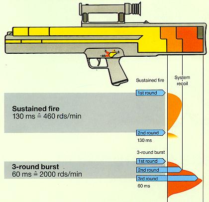
The G11 used a counter-recoil buffer mechanism to allow high rates of burst fire. When firing three round bursts the weapon send the rounds downrange at a rate of ~2,000 rounds per minute, only when the last round has left the barrel does the barrel and action begin to recoil inside the stock along a central guide. When in sustained fire the rate of fire is closer to ~460 per minute.
H&K promotional diagram showing the G11’s mounted recoil system (source)
The buffer spring below the barrel is compressed as the recoiling barrel and breech assembly moves. In sustained fire the buffer spring is partially compressed with each round, but in burst fire the buffer is compressed to its maximum hitting before the buffer housing (which is when recoil from the burst is felt by the operator), this is described as having the barrel and breech assembly ‘float’.
To ready the weapon to fire a magazine was loaded into the magazine channel on top of the G11, a magazine dust door, which automatically closed when unloaded, was depressed as the magazine was pushed home. The cocking handle on the left side of the butt was then actuated. The operator rotated the handle 360-degrees counter-clockwise until the weapon was cocked (essentially like winding a clock). The same process will eject any rounds left in the chamber once the magazine has been removed.
Gas tapped from the barrel cycles the cylinder drive system with gas pushing a piston back to act on a series of gears which rotated the rotary breech from horizontal to vertical to allow a new cartridge to drop into the breech. There was a vent for high pressure gas underneath the butt stock this prevented pressure build up and mitigated some of the thermal build up.
Members of the Gebirgsjäger (Bundeswehr alpine light troops) on the march with G11s (source)
The G11 K1 was tested by the German Army in the late 1980s with adoption planned for the early 1990s. Heckler & Koch continued to develop the G11, entering the G11 K2 into the US Army’s Advanced Combat Rifle (ACR) trials alongside entries from Steyr, AAI and Colt [all of which we will examine in upcoming videos]. However, the fall of the Berlin Wall in 1989 and the collapse of the Soviet Union in 1991 meant that West Germany no longer had the huge amount of funds needed to field the G11. At the same time the ACR program ended inconclusively and the G11 project was finally abandoned.
The extreme complexity of the design, the inadequacy of the weapon’s ergonomics and its inevitably high production cost casts doubt on whether the G11 would ever have seriously been considered for widespread adoption. Regardless of this the G11 is a fascinating footnote in small arms history representing a false start along a technological avenue which, with the Lightweight Small Arms Technologies (LSAT) program, may still prove fruitful. Heckler & Koch and Dynamit-Nobel’s ambitious design marks one of very few serious and potentially successful attempts engineers to overcome the plateau that firearms technology is currently stuck on.
Stripping the HK G11
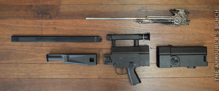
G11 ACR disassembled to its major assemblies (Matthew Moss)
Matt recently had the opportunity to disassemble a G11 and get a look inside the action. In this special video and accompanying full-length article he explains how the rifle strips and how it works! Check out the video here.
If you enjoyed the video and this article please consider supporting our work here.
HK G11 Caseless Ammunition Weapon System. The G11 Rifle. HK Factory Brochure, 1989 (source)
Our thanks to the collections that hold these examples of the G11. While one wishes to remain anonymous, we would like to thank the Dutch Military Museum for access to their G11.
Matt recently had the opportunity to visit the excellent Menorcan Military Museum at Es Castell, on the Spanish Balearic Island of Menorca. The museum is well worth a visit with some very rare and extremely interesting weapons on display.
An M45 mounted on a M16 half-track during World War Two (source)
The M45 Quadmount was developed by the W.L. Maxson Corporation for the US Army. It mounted four .50 calibre M2 Browning Heavy Machine Guns on a lightweight, rotating powered mount. I recently had the opportunity to take a closer look at an M45 while visiting the Menorcan Military Museum.
Introduced in 1943, the M45 was capable of 360 degrees of rotation and 90 degrees of elevation. It was manned by a three man crew: two loaders, who loaded the M2 Browning’s 200-round belt drums, and a gunner.
The M45 was extremely versatile and could be mounted on a number of trailers and vehicles including the M20 and M17 trailers and the M16, M17 and M51 half-tracks.
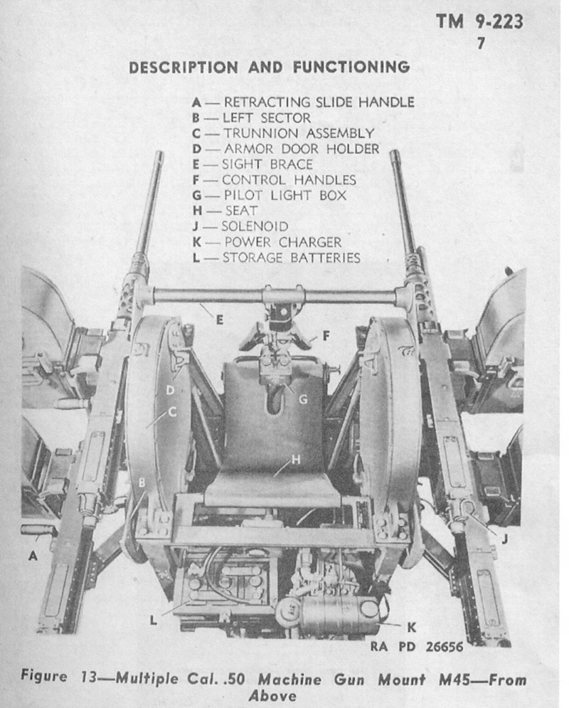
Diagram from the M45’s manual showing the layout and some of the Quadmount’s parts (source)
The gunner sat on a canvas seat inside the M45, between the two pairs of guns. He controlled the aiming of the guns with two control handles and aimed the M45 through a reflex sight which was mounted to a sight bar.
The M45 was powered by two 6-volt batteries and weighed approximately 2,400lb (1,090kg). The gunner was protected by an armoured plate at the front with two hinged armour plates either side of the M1X reflex sight. The M45 mounted four M2 TT (Turret Type) varriant machine guns – these were fired by solenoids. All four of the guns could be fired at once but gunners normally alternated between the upper and lower pairs in order to allow the guns to cool and loaders to replenish the drums.
An M45 mounted on an M17 half-track during the Korean War (source)
When all the guns were fired together the M45 had an impressive rate of fire of approximately 2,300 rounds per minute. The Quadmount saw action throughout World War Two, the Korean War and in Vietnam. However, with the beginning of the jet age the M45 became increasingly obsolete in the anti-aircraft role. It continued to be used against ground targets with many mounted on vehicles to create ‘gun trucks’.
If you enjoyed the video and this article please consider supporting our work here.
At the beginning of the Second World War the Australian Army, much like Britain, lacked a standard issue submachine gun. Following Britain’s lead a small number of Thompson submachine guns were ordered for trials purposes in early 1941. The Australian military eventually purchased 18,382 Thompson M1928A1s, however, it was realised that an indigenously produced weapon was needed.
1941 saw extensive testing and development of Evelyn Owen’s submachine gun, at the same time technical drawings for the Sten arrived from Britain. The Australian engineers that examined the Sten believed that it was too rudimentary for Australian needs. In September 1941, the Melbourne-based Die Casters Ltd. were contracted by the Ordnance Production Directorate to investigate improving the Sten. W.T. Carmichael & Sons Ltd were also interested in producing submachine guns and both Carmichael and Die Casters were contracted to produce the improved Australian Sten gun.
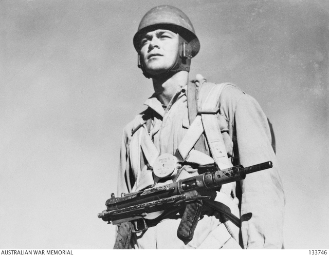
Austen-armed Paratrooper from the Australian parachute battalion training centre, c.1945. The Austen’s folding stock made issue to paratroops one of the few roles that the Austen was better suited to than the Owen gun (AWM)
The Austen was based upon the MkII Sten, however, substantial changes to the design were made. These included a new folding stock based upon the German MP38/40 stock, an added forward pistol grip and a cocking handle slot which ran almost the full length of the tub receiver. This longer slot opened allowed greater ingress of mud and dirt. The most significant internal change was the use of the MP40’s bolt and telescoping return spring. The magazine housing was die cast while the rest of the weapon’s parts were stamped steel. Some aborted attempts by Die Casters Ltd to incorporate die casting production methods lead to early failures but by early 1942 the weapon was ready for production.
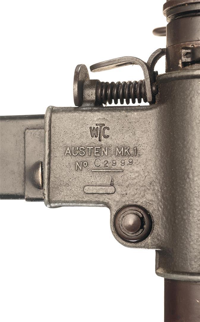
A close up of the Austen’s Diecast magazine housing (RIA)
Like the Sten, the Austen was a simple blowback submachine gun, chambered in 9x19mm and feeding from a 32-round magazine which fed horizontally from the left. With its stock folded it was 52cm long and weighed 3.9kg (8.8lb) unloaded. By contrast the heavier but more reliable Owen weighed 4.2kg (9.3lb). The Austen’s fixed rear aperture sight was fixed at 100 yards.
The new folding stock increased the weight of the Austen, it was also slightly longer than ideal in order for the butt plate to clear the forward handgrip. Some troops complained that this made the weapon’s length of pull too long. In general the Austen required more parts and was more expensive and complex to manufacture. Some Sten parts were interchangeable with the Austen, as were Sten magazines. Like the Owen it appears that at least some Austens were fitted with suppressors similar to that of the Sten MkII(S) and MkVI.
The photograph above shows Lt.Colonel Tucker, commanding officer of the 2/23 Infantry Battalion, testing a suppressed Austen in Borneo in September 1945. Note also the suppressed Owen Gun in the background (AWM)
As Australia was in desperate need of submachine guns both the Owen and Austen were ordered into production. The Austen, however, suffered from a series of delays and quality control issues. As a result only 2,100 Austens had been issued, out of over 16,000 made, to troops by early 1943. In total 19,914 Austens are thought to have been built, most of these were factory spray painted with a camouflage pattern (see image #3) In contrast 45,400 Owen guns were produced by June 1945. The Owen was certainly favoured by troops in the field. A report written following troop trials with 300 Austens noted that the weapon’s working parts were exposed, it didn’t function as well as the Owen after submersion in mud and water, it lacked a flash-hider, its stock was too long and was less accurate than the Owen. The Owen, while heavier, was appreciated for its reliability, ergonomics and balance.
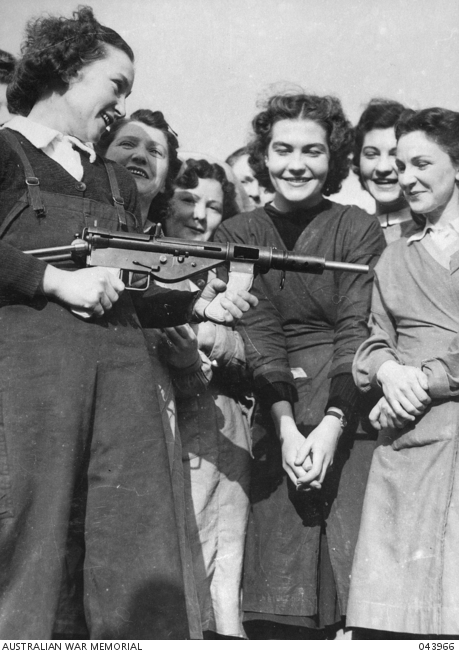
Australian women war workers pose with an Austen (AWM)
Attempts were made to produce an improved MkII Austen, which used more die cast parts, however, this was not adopted and only 200 were made. By the end of the war the Austen had been removed from frontline service and placed in reserve. Dutch troops in the Dutch East Indies (present day Indonesia) also used a number of Austens during the Netherlands’ period of decolonisation in the region between 1945-1949. The Owen Gun continued to be used into the 1960s, seeing action in Korea, Malaya and Vietnam before it was replaced by the F1 submachine gun.
If you enjoyed the video and this article please consider supporting our work here.
Matt recently had the opportunity to visit the excellent Menorcan Military Museum at Es Castell, on the Spanish Balearic Island of Menorca. The museum is well worth a visit and the Maxim-Tokarev was one of the very rare and extremely interesting weapons they have on display.
Soviet troops disassembling an MT light machine gun, note the hinged stock pivoted down to allow access to the action (source)
The Maxim-Tokarev (MT) Light Machine Gun was developed at the request of the Soviet military high command in the early 1920s, following the end of the Russian Civil War. Influenced by the German MG08/15, Tokarev set out to lighten the Maxim M1910. The MT was one of two designs submitted for testing. Designed by Fedor Tokarev, at the Tula Arms Factory, the MT was tested along side Ivan Kolesnikov’s similar Maxim-Kolesnikov light machine gun. Development ended in 1924 and the MT went into initial production in 1925 with the first weapons successfully tested against the Maxim-Kolesnikov.
The MT’s principle rival the Maxim-Kolesnikov, note the unconventional butt stock (from Chinn’s The Machine Gun Vol.2)
Production continued until at least 1928, while many sources suggest 1927, the example featured in the video dates from 1928. Sources suggest Tula produced 3,500, however, this number does not match with the suggested export numbers and the featured example is serial number 5283.
Tokarev, and his son, posing with several MT light machine guns, c.1925 (source)
The MT is based upon the Russian M1910 Maxim gun, using the same short recoil, toggle locked action. It was hoped that established tooling would be able to make some of the new light machine gun’s parts. The weapon weighed 12.9kg unloaded and Tokarev made extensive efforts to lighten the weapon with the the water-cooled barrel jacket replaced by a perforated shroud to allow air cooling. The receiver also has a large number of lightening cuts to shave off weight.
In his 1952 book ‘The Machine Gun Vol.2, Pt. VII’, George Chinn suggested that the Tokarev may have been influenced by an earlier design patented in 1909, by Vickers Sons & Maxim Ltd. designers Arthur Dawson and George Buckham. The patent shows a Maxim-derived light machine gun with a very similar layout to the MT.
Dawson & Buckham’s patent for a Maxim light machine gun (Patent)
The M1910’s spade grips were replaced by a wooden butt stock and a new trigger mechanism and a non-adjustable bi-pod was added at the muzzle. The butt-plate was hinged to offer additional stability and the weapon’s barrel could be changed in the field.
The MT fed from a 100-round canvas belt and chambered the standard Russian 7.62x54mmR cartridge. The belt was held in a drum suspended beneath the weapon and when loaded weighed approximately 15kg. Following troop trials a number of changes were suggested, some improvements were made but the decision was made to move away from the MT.
Spanish Republican troops defend a barricade with an MT (source)
The MT was eventually replaced in Russian service in the late 1920s by the Degtyaryov-designed DP-28 light machine gun. The remaining MTs were sold to Spain and China during the 1930s. These guns saw extensive use during the Spanish and Chinese Civil Wars.
If you enjoyed the video and this article please consider supporting our work here.
At the end of the Second World War the British Army had two primary infantry machine guns: the Bren light machine gun and the Vickers medium machine gun. These weapons had proved their worth, the Bren was especially well liked and the venerable Vickers continued to be a reliable workhorse.
In the late 1940s, the British Army recognised the Soviet threat to Western Europe. In 1947, Field Marshal Bernard Montgomery, the newly appointed Chief of the Imperial General Staff wrote a paper outlining rearmament plans based on intelligence estimates of how quickly the Soviet Union was likely to be ready for another full-scale war. Montgomery believed that Britain had just 10 years to develop new weapons and begin rearmament before the Soviet Union had recovered enough to launch an invasion of Western Europe. As such the British Army felt that rearmament needed to be complete by the late 1950s.
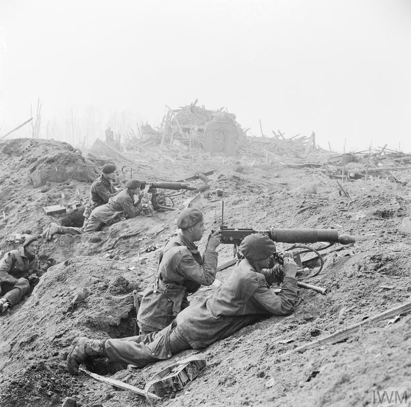
Two Vickers medium machine guns in action in Wesel, 1945 (IWM)
A number of large budget programmes were launched while small arms projects were also undertaken. These included the Infantry Personal Weapon programme which sought to develop a new intermediate calibre infantry rifle – the IPW programme later yielded Stefan Janson’s EM-2, a bullpup chambered in .280, which was briefly adopted as the Rifle No.9. The FN FAL was later adopted due to changes in political circumstances – a long, fascinating story for another article. The companion to the IPW programme was the development of a Sustained Fire Machine Gun also chambered in .280. The TADEN, a belt-fed derivative of the Bren firing the new .280 round, was designed by Harold Turpin (‘T’), the Armament Design Establishment (‘AD’) and Enfield (‘EN’). With the abandonment of the IPW the TADEN was also abandoned but its design greatly influenced the later X11 developments.
Another major small arms programme at the time was the search for a new machine carbine (or submachine gun). This saw the testing of designs from Sterling, BSA and Madsen – with the Sterling finally adopted as the L2.
The other major small arms project was the programme to find a new section level machine gun. The German MG34 and MG42 had impressed the Allies during the war, so much so the US went as far as to clone it with the T24. After the abandonment of the EM-2 and TADEN machine gun the British issued a new specification for a lightweight sustained fire machine gun, chambered in the 7.62x51mm round recently adopted by NATO, in the mid-1950s.
The design team at the Royal Small Arms Factory at Enfield developed a belt-fed derivative of the Bren light machine gun. The X11 series of prototypes sought to convert the Bren’s proven design into a weapon capable of sustained fire. The X11 made a number of changes to the Bren included the addition of a detachable butt/grip/trigger assembly which could be swapped for a pair of spade grips and a paddle trigger for static sustained fire from a tripod. This resulted in the pistol grip being located much further back than the traditional Bren’s.
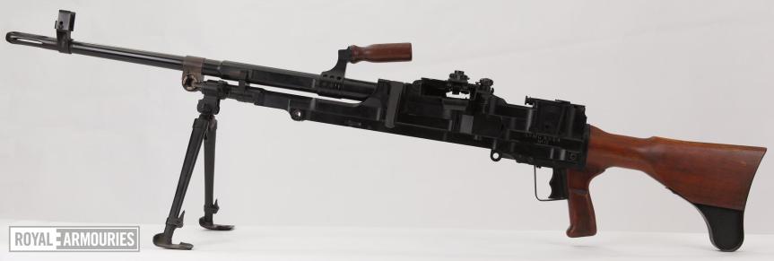
The X11E2 set up for the sustained fire role on a tripod with the spade grips and an optical sight similar to the UNIT sight. (Royal Armouries)
It appears that during the mid-1950s British military parlance described the General Purpose Machine Gun as a Sustained Fire Machine Gun (SFMG). From the available photographs it appears that the L4 and X11 use the same barrel with its distinct flash hider. The receivers of all the prototypes appear to be milled to attach the optical long range sight seen above.
The main drawback with the X11 was its feed mechanism. The feed slide was indexed by a rotating vertical feed shaft which was driven by the gas piston’s recoil. This created a considerable amount of friction within the action. It had the effect of causing failures to feed during adverse conditions testing and elevated firing tests. A series of four X11 prototypes were developed with Harold Turpin (co-designer of the STEN gun and later TADEN) working on the new gun. Each prototype appears to have a sightly different trigger configuration. The most interesting of these is a two-finger double-crescent trigger reminiscent of the MG-34’s – from the photographs it appears that the conventional selector lever, used in the X11E2, was replaced with a fire-selector system similar to the MG-34’s (upper crescent – semi-auto, lower crescent – full-auto). However, the trigger of the example of the X11E4 examined by Vic (serial number #11) was fully automatic only, despite its crescent shape.
Below are photographs of examples of the three types held at the Royal Armouries:
X11E2, note the large cutout in the receiver in front of the trigger group (Royal Armouries)X11E3 (Bren Gun Saga, Dugelby)X11E4, note double-crescent trigger (Royal Armouries)
The X11 was tested against the M60, French AA-52, Swiss MG51, Danish Madsen-Saetter, German MG-3, and the Belgian FN MAG. The FN MAG, designated the X15E1 by the British, fared best in the trials with the X11 coming second due to its feeding issues. In January 1958, the British abandoned the X11 and moved to adopt the X15E1 general purpose machine gun, negotiating a license for its manufacture. The weapon was finally adopted as the L7A1 in 1961, with production at Enfield beginning in 1963. It seems that the Birmingham Small Arms Company were a latecomer to the competition having developed the another belt-fed Bren gun derivative known as the X16.
The Bren did continue in service after the switch to 7.62x51mm. In 1954, before beginning work on the X11, Enfield had developed the X10E1. Taking a Canadian manufactured 7.92x57mm Bren breech block and converting it to cycle the new round. The X10E1 was formally adopted as the L4. The L4 remained in service, alongside the L7, into the early 1990s. The L7 GPMG continues to be used by the British Army.
If you enjoyed the video and this article please consider supporting our work here.
In the late 1760s a Milanese machinist/clockmaker Giuseppe Crespi developed a breech-loading system for the Austrian Empire. Working with Ambroglia Gorla Crespi built a practical breech loader which was eventually adopted and fielded by the Austrian army during the 1770s. Crespi’s system is a lesser known contemporary of the Girandoni air rifle.
Crespi and Gorla’s system was designed to be a conversion of standard Austria’s muzzle-loading carbines. It used a hinged breech which tipped up to allow powder and then a ball to be loaded into the chamber. The breech was then closed and the handle locked into a pair of lugs mounted to the barrel. Austrian Emperor Josef II ordered testing of the design and over 350 were initially ordered and delivered by June 1771.
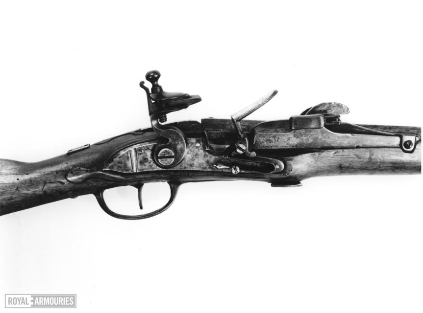
A later Crespi System Breech-Loading Flintlock Volunteer Carbine dating from 1810 – note the different orientation of the locking handle (source)
Despite some wrangling over payment a further order for 2,000 guns using Crespi’s system was made in 1772. These were to be made by the Ferlach gunmakers association in southern Austria and Crespi was paid a lump sum settlement for his design. Gorla’s role in the development of the system is unclear and he did not receive a settlement from the government. In 1771, he sued Crespi for his share but the courts threw out his claim in 1778.
A 1770 Austrian Crespi breech-loading carbine with a hooked breech arm, held by the Royal Armouries (Courtesy of the Royal Armouries)
The principle problem with Crespi’s system was that it was not gas tight, a problem which plagued many early breech-loading systems. As can be seen in the images above the breech block is flat where it meets the breech. This allowed gas to escape and troops complained the chamber was susceptible to wear. The Crespi carbines were issued to Austrian cavalry with a long bayonet, some sources also suggest a spear point bayonet. The bayonet was carried reversed suspended in the carbine stock. The Austrian carbines were removed from service in 1779, following numerous reports of men being badly burned by escaping gases and opening breeches during the War of Bavarian Succession.
In 1768, Crespi was also allegedly hired by the Portuguese crown to establish a factory at Coimbra to manufacture guns using his system. By 1776,Crespi no longer had any interests in the factory and it was taken over by Companhia de Armamento who continued to manufacture conventional muzzleloading muskets.
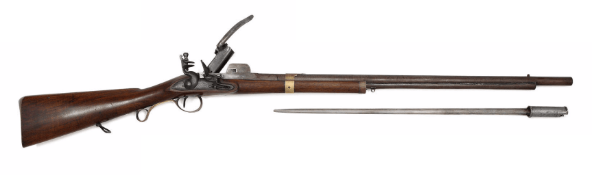
An Egg breechloading Carbine which borrowed heavily from Crespi’s design (source)
In the early 1780s, the Duke of Richmond became the Master General of Ordnance and ordered a selection of breech loaders for trials. Two of these came from Swiss-born London Gunmaker Durs Egg. Egg’s carbine was a copy of Crespi’s system. The carbines were tested by a board of general officers in July 1784 and it was recommended that the carbine be issued to the Light Dragoon regiments. Egg was paid £31 10s for two carbines with one being presented to King George III and the other retained by the Ordnance office. Sources suggest a further 36 breech-loading carbines were ordered from Egg. In 1786, these were issued to the 7th, 10th, 11th, 15, and 16th Light Dragoons for field trials. These are often reffered to as the Pattern 1785 Egg/Crespi carbines, some of these trials guns were rifled for testing.
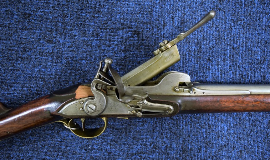
The carbine with its breech partially open. Egg’s carbine was loaded by placing either loose power and ball or a paper cartridge containing power and ball into the breech block (Author’s photograph)
The Egg carbines were almost as long as a standard issue Short Land Pattern (Brown Bess) musket which was 58 inches or 150cm in overall length. Based on surviving examples it seems the smoothbore Egg carbine was 48.1 inches or 122cm overall while the rifled version was slightly longer at 53 inches or 135cm in length. This combined with the long reach of the spear bayonet, an estimated 35 inches (88cm) long, made for an extremely long weapon – certainly capable of reaching any mounted assailant a dragoon might face while dismounted. Unlike the Brown Bess’ the rifle fired a .60 calibre ball while the smoothbore fired a .68 calibre ball.
A standard dedicated carbine was not introduced for Britain’s light dragoon regiments until 1796. Until then the Short Land Pattern musket had been issued to dragoon regiments. The trials report was returned in 1788, recommending that more experimentation with the rifled carbines should be carried out and that a folding bayonet may be better suited to cavalry use.
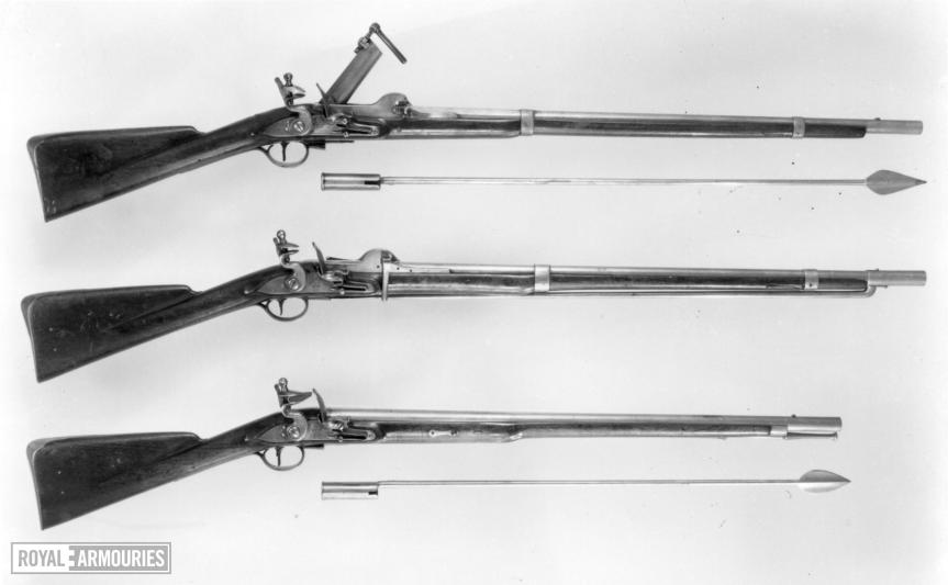
Pattern 1785 Crespi-system Egg breechloaders, the second has Hennem’s screwless lock. The carbine at the bottom is a muzzle-loader, all three have the unusual spear bayonet (Courtesy of the Royal Armouries)
The lack of a gas seal at the breech was also criticised and the Duke of Richmond began to explore other designs including those by Henry Nock. Tatham & Egg (Egg’s nephew) continued to manufacture weapons using the Crespi system until at least 1810, when some were made for volunteer yeoman cavalry (with serial numbers ranging up to at least #134). Crespi’s system would be improved by Urbanus Sartoris in 1817, with the addition of an interrupted screw and a moving barrel. Giuseppe Crespireportedly died in poverty and his breech-loading system became another footnote in the early history of breech loading firearms.
If you enjoyed the video and this article please consider supporting our work here.
Bibliography:
John H. Hall and the Origin of the Breechloader, D.B. Demeritt Jr., (source)
British Military Firearms 1650-1850, H.L. Blackmore, (1961)
The Austrian Army 1740-80: Cavalry, P.J. Haythornthwaite, (1994)

.Movie_Snapshot")
.Movie_Snapshot")
.Movie_Snapshot")
.Movie_Snapshot")
.Movie_Snapshot")