In addition for the full episode on the Winchester Experimental Submachine Gun, we have also put together a video showing the reassembly process for the N2 prototype that we disassembled and examined in the main video. Check it out below:
My thanks to the Cody Firearms Museum at the Buffalo Bill Center of the West for allowing me to examine and film the Winchester submachine gun prototypes. Special thanks to the CFM’s assistant curator Danny Michael for helping disassemble and reassemble the N2.
If you enjoyed the video and this article please consider supporting our work here.
Held in the collection of the Cody Firearms Museum (CFM), at the Buffalo Bill Centre of the West, is a most intriguing Cold War submachine gun. The weapon came from the collection of the old Winchester Firearms Museum, which the CFM inherited, it is not a test & evaluation weapon made by another company but a submachine gun designed and developed by Winchester. Those who know their Winchester history will know the company had no prior background in submachine gun design, instead being best known for their rifles and shotguns.
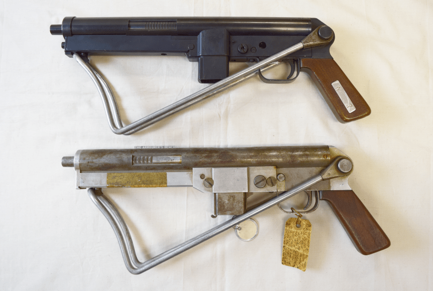
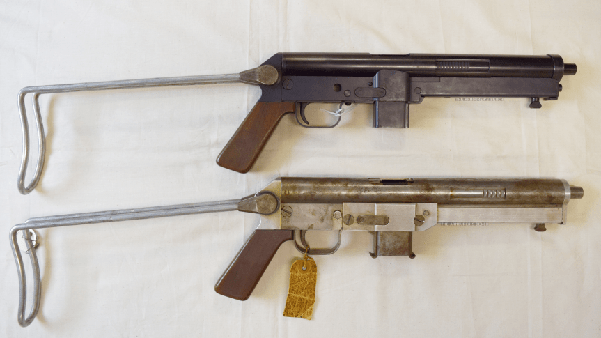
Left side profile view of the N4 and N2 Winchester submachine gun prototypes with their stocks folded (Matthew Moss)
Very little is known about Winchester’s submachine gun project, but two prototype examples survive, an early ‘in the white’ model labelled ‘N2’ and another which Herbert Houze, the CFM’s former curator, designated ‘N4’ . The documentary evidence for the Winchester submachine guns is sparse, amounting to just entries in the Winchester Museum’s inventory and a faded battered item tag attached to N2. A confusing element is that the inventory simply refers to the two prototypes as N-1 and N-2, with no mention of an N4.
There is also believed to be original engineering drawings housed in the Winchester Archival collection, currently held by the McCracken Research Library, but searches by myself and library staff have been unable to locate these.
It is unclear if the tag from N2 is contemporary, perhaps added when the gun was handed over to Winchester’s museum, or if it was added later. In under 100 words it give us a short potted history of the N2 itself and the company’s programme to develop a submachine gun.
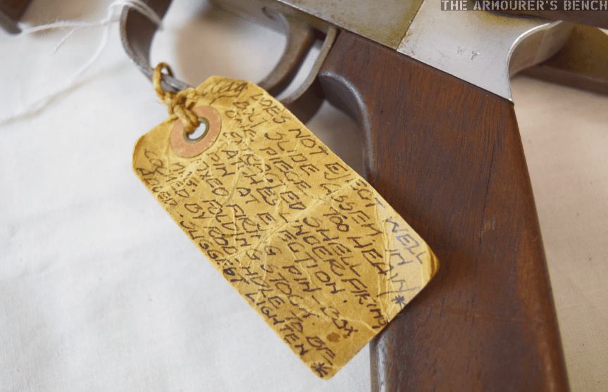
Close up of the N2’s item tag detailing the gun & program’s history (Matthew Moss)
Houze suggests the development programme began in 1955 and the tag attached the N2 suggests that development ceased in 1957, whether this is solely for that gun or the entire programme is unclear. This would make Winchester’s weapon a contemporary of the famous Israeli UZI.
The tag describes the N2 as a 9mm blowback ‘NATO Burp Gun’, followed by the name A.A. Arnold, a Winchester engineer perhaps best known for writing a series of manuals for Winchester firearms, followed by ‘dropped Dec ’57’. In his 1994 book, Winchester Repeating Arms Company: Its History & Development from 1865 to 1981, Houze suggests that the weapons were designed by A.A. Arnold and Melvin M. Johnson in 1955, for possible adoption by NATO. The association with NATO might also be the origins of the ‘N’ prefix. I have been unable to find any published patents attributed to Arnold, Johnson or the company relating to the experimental submachine gun.
I contacted NATO’s Archives who advised that they were unable to find any reference or documentation relating to a direct NATO submachine gun requirement. Another possibility is that the weapon was developed to market more broadly to NATO member nations. The submachine gun market at this time in Europe, however, was already saturated by both wartime surplus and a new generation of guns, including the Sterling, the UZI, the Madsen M50, and the Carl Gustav m/45.
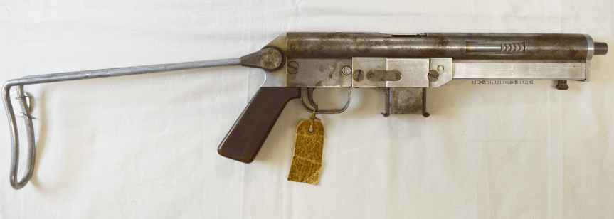
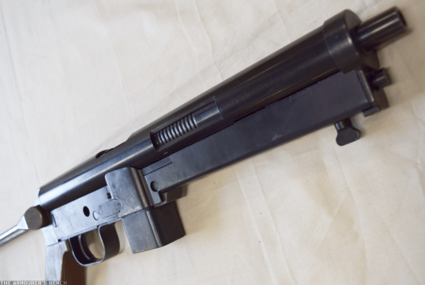
Right side profile view of the N2 ‘in-the-white’ prototype with its stock deployed (Matthew Moss)
The reverse of the N2’s label documents the prototype weapon’s reliability and feeding problems. The tag states that the N2 did “not eject well” and that the bolt slide assembly was too heavy. It also highlights failures to cycle properly with extracted cartridge cases catching under the firing pin. The label then gives a brief description of some of the N2’s features: “fixed firing pin, 33x Mag. Folding stock.” Interestingly, it also notes that the weapon would be cocked by a rod – the hole for which had not yet been added. The tag ends with a suggestion that the heavy one piece bolt assembly should be lightened.
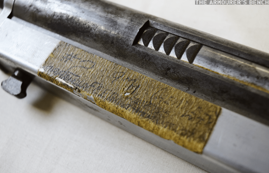
Close up of the N2’s difficult to decipher tape note (Matthew Moss)
N2 itself also has a piece of masking tape, on the recoil spring assembly cover, with its serial number and calibre written on it, along with A.A. Arnold’s name and some words that are too difficult to make out, but include ‘feed’.
Houze has also suggested that Melvin Johnson, designer of the Johnson rifle and light machine gun who joined Winchester as a designer and adviser in the early 1950s for a short time, and Stefan Janson, designer of the Brtish E.M.2 bullpup and subsequent Winchester engineer, both worked on the project. However, I have been unable to find any documentary evidence of their involvement.
Examining the N2:
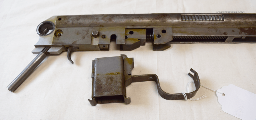
Winchester N4 and disassembled N2 prototype (Matthew Moss)
We can learn a lot from hands on examination of the two Winchester ‘N’ prototypes. Examining N2 we find that the receiver is made up of a piece of shaped sheet metal with a rounded upper half containing the barrel, bolt and cutouts for the grip points on the bolt assembly that allow charging. The bolt assembly rides over the rear portion of the barrel and projects back into the receiver. The lower section of the stamped receiver is rectangular and has a cut out for a separate magazine housing and fire control mechanism consisting of a trigger and push through safety – which we did not remove during disassembly. The N4 is missing its safety.
Close up of the N2’s magazine housing and trigger guard, note also the trunion freed from the receiver (Matthew Moss)
In the N2, the magazine housing is held in place by the stamped metal trigger guard which rocks into a notch behind the trigger and at the front interfaces with a notch in the magazine housing which has to be placed in the receiver at the same time, both are then held in place by a screw. This was changed in the later ‘N4’ with the trigger guard as a separate independent piece.
Winchester N2 Prototype Reassembly:
The side plates, muzzle end cap and recoil spring assembly cover all made from Aluminium – ostensibly to reduce weight. The submachine gun prototypes both use a pinch cocking method similar to that seen in the earlier British BSA WELGUN developed during WWII. The recoil spring proved to be too strong to cock easily, the addition of ‘rod’ cocking handle is suggested on the N2’s tag. The blued, later N4 prototype, however, is still lacking a conventional cocking handle. The pinch cocking method is not ergonomic, the user’s fingers could easily be caught by reciprocating bolt in charging cut outs in the receiver.
The N2 prototype disassembled, sadly we were unable to free the bolt from the receiver (Matthew Moss)
Another ergonomic consideration is the Winchester’s submachine gun’s unusually swept back pistol grip angle, the angle of the forward grip made by stock when folded is also similarly angled. Both the weapons have a push though safety selector just above the trigger (likely safe & fully automatic, but could not check as gun unable/difficult to cycle the prototypes easily). The weapon likely fed from a double stack, single feed magazine – either of an similar pattern to the MP40 or proprietary. The N4 seen in Houze’s 1994 book is shown with an MP40 magazine. UZI magazines fit the weapon but don’t lock into place.
The basic design does not change substantially between the prototypes with the control configuration, folding wire stock, pistol grip angle and magazine housing dimensions remaining the same. The N4, however, differs from the earlier prototype in a number of respects. The N4’s nose cap now fits over the rounded half of the receiver, rather than sitting flush and the cut outs in the upper receiver to access the bolt assembly for charging have been moved back slightly.
Right side view of the N4 blued prototype, note the half cocked bolt and the narrower grip serrations on the bolt assembly. Note also the intersection points of the recoil spring assembly cover and the upper receiver (Matthew Moss)
The later N4 model has pins in place of some of the screws used on the N2. The side plates have been replaced by a one-piece recoil spring assembly cover which projects back further over the magazine housing to the rear of the receiver. The most fundamental difference between the two is that it appears that the front part of the N4’s receiver has been significantly altered with the lower receiver at the front of the gun removed. It appears to have been replaced by the recoil spring assembly cover which appears to slot into the receiver. Sadly, we didn’t have time to disassemble the N4 to examine this.
The N4’s bolt assembly also has more serrations, in a slightly different orientation, on its bolt assembly gripping area, but still no charging handle as recommended on the N2’s tag. The ejection port on the blued prototype is also at a position closer to 12 o’clock when compared to the N2s.
Right side profile view of the two prototypes with their stocks deployed (Matthew Moss)
The N2 has a metal trunnion block, that the recoil spring guide rod screws into, this is held in place within the receiver by a cross pin. The bolt appears to be removed through the rear of the receiver once the stock assmbly/end cap is removed and the bolt assembly freed.
The folding stock was retained by spring tension of the wire metal stock against a wingnut-shaped catch that is riveted onto the recoil spring assembly cover. The stock is locked by a spring loaded push button system similar to the MP40s, this is not particularly sturdy. The shape of the wire stock itself is reminiscent of the US M3. When folded the butt of the wire stock acts as a front grip, the retention of the stock is surprisingly strong and stable.
Intriguingly, the Winchester Museum inventory notes that the guns are designated the N-1 and N-2, with an additional wooden model of the ‘Nato Burp Gun’ being transferred along with a box of duplicate parts in steel for the N2’s aluminium parts.
If you enjoyed the videos and this article please consider supporting our work here.
Winchester Repeating Arms Company: Its History & Development from 1865 to 1981, H. Houze (1994)
My thanks to the Cody Firearms Museum at the Buffalo Bill Center of the West for allowing me to examine and film the Winchester submachine gun prototypes. Special thanks to the CFM’s assistant curator Danny Michael for helping disassemble the N2.
All photographs taken by Matthew Moss, courtesy of the CFM & the Buffalo Bill Center of the West. Please do not reproduce photographs without permission or credit.
Today we’re examining an intriguing firearm with a fascinating history. It is difficult to understate the potential importance of the Curtis Rifle. Despite being designed in Britain in the 1860s the firearm gained more notoriety when it was offered as evidence in a legal battle between the Winchester Repeating Arms company and Francis Bannerman. What makes the firearm most noteworthy, however, is its fundamentally unconventional layout. Designed by William Joseph Curtis in the mid-1860s, it is arguably one of the earliest ‘bullpups’ and almost certainly the first repeating bullpup.
William Curtis’ 1866 ‘bullpup’ rifle, built in 1895 by Winchester (Photo by Matthew Moss, courtesy of the Cody Firearms Museum)
For the purpose of this article it would be wise to first define what a bullpup actually is. It can be defined as a weapon with a somewhat unconventional layout which places the action and magazine behind the weapon’s trigger group. This has the benefit of maintaining a conventional rifle’s barrel length while making the overall length of the rifle more compact.
Bullpup rifles became popular with a number of militaries around the world during the 1970s and 1980s – namely the Austrian Steyr AUG, the French FAMAS and the British SA80, and more recently with rifles from China and Singapore as well as the Tavor series of rifles from Israel.
Thorneycroft, Farquhar and Hill’s 1905 carbine patent (source)
The bullpup, however, dates back much further with some argument to be made for the first firearms to utilise the concept being 19th century percussion target shooting rifles. The earliest military bullpups date to the beginning of the 20thth century, these include a rifles designed by Samuel McClean, the initial designer of the Lewis Gun, patented in 1896 (US #723706), by Major Philip Godsal (US #808282) and a carbine developed by James Baird Thorneycroft in 1901. Thorneycroft subsequently worked with Moubray Gore Farquhar and Arthur Henry Hill to patent a refined version of the carbine in 1905 (US #827893). While the Thorneycroft was tested by the British army it was rejected due to ergonomic and reliability shortcomings.
In 1908 Lieutenant-Colonel Armand-Frédéric Faucon of the Troupes Coloniales (French Colonial Infantry) began developing what he termed a ‘Fusil Équilibré’ or balanced rifle. Faucon patented his concept in France in 1911 (FR #422154) and continued to work on the balanced rifle during World War One, utilising a Meunier A5 semi-automatic rifle in working prototypes. The Faucon-Meunier rifle was tested in 1918 and 1920 but eventually rejected. It would be nearly 45 yeas before the bullpup concept was revisited by a major power. Engineers working at the Royal Small Arms Factory at Enfield and at the British Armament Design Department in the 1940s began to develop designs based around the bullpup concept. (Some of these will hopefully be the focus of future videos!)
William Curtis’ design, however, predates all of these. Patented in Britain on 10th July, 1866, Curtis is listed by the London Gazette as a Civil Engineer. His design is unlike anything that had been seen before. Based on a slide-action with a drum magazine, it was placed over the shoulder – much like a modern shoulder-fired anti-tank weapon.
William Joseph Curtis’ July 1866 patent for ‘Breech actions, sliding breech-block & stocks’ (courtesy of Research Press)
Curtis’ rifle is probably the very first bullpup magazine rifle, one of the earliest to have a drum magazine (an Italian, Marco Antonio Francois Mennons, patented an earlier design for a drum magazine in March 1862, GB #637) and also an early striker-fired design. Clearly a design well ahead of its time and radically unconventional.
This unconventional gun’s designer was born in Islington, London in 1802, as a civil engineer he worked on Britain’s rapidly growing railway network. He died in 1875, placing the development of his rifle nearer the end of his life. With hindsight Curtis’ design clearly had revolutionary potential but it appears that his concept was never taken up. It appears that he only patented his design in the United Kingdom. If not for a corporate lawsuit on another continent, decades later, then it is possible Curtis’ design, like so many others, would have slipped into historical obscurity.
Francis Bannerman vs. the Winchester Repeating Arms Company
In 1890, Francis Bannerman VI, a successful entrepreneur specialising in junk, scrap and later surplus, purchased the Spencer Arms Company and the rights to their patents. The company had been founded by Christopher Miner Spencer, designer of the Spencer Rifle, they produced the first commercially successful slide or pump-action shotgun. This pump action shotgun was designed by Spencer and Sylvester H. Roper and patented in April, 1882 (US #255894). Bannerman continued producing the shotgun as the Bannerman Model 1890, however, in 1893 the Winchester Repeating Arms Company, introduced the John Browning-designed Model 1893 pump shotgun (US #441,390).
Spencer & Roper’s 1882 patent for their pump action shotgun (source)
In response in October 1894, Bannerman filed a law suit against the Winchester Repeating Arms Company claiming that the slide/pump actions used by Winchester’s Model 1890 and new Model 1893 shotgun infringed on the patents that he owned.
He called for the court to force Winchester to halt production and claimed $10,000 in damages and royalties for the sale of guns which he believed infringed his patent. Winchester temporarily halted production of the Model 1893, in the meantime Bannerman continued producing and improving his shotgun introducing the 1894 and 1896 models.
News report on the ruling of the Bannerman vs Winchester case from The Times (Philadelphia), 27th June, 1897
Various contemporary newspaper reports suggest between 100,000 and 500,000 people were directly interested in the case as ordinary owners were liable under the conditions of Bannerman’s suit.
Winchester dispatched George D. Seymour to Europe to scour the French and British patent archives for any patents for similar actions that had been filed there before those now owned by Bannerman. Winchester discovered four patents: three British and one French. The earliest of these was Alexander Bain’s patent of 1854. Two more patents held by Joseph Curtis and William Krutzsch were found, dating from 1866. The later French patent was filed by M.M. Magot in 1880. All of these designs, including the Curtis we are examining here, never progressed beyond the development stage and were largely forgotten until rediscovered by Winchester.
Model of William Krutzsch’s pump action rifle (Photo by Nathaniel F, courtesy of Cody Firearms Museum)
Winchester claimed that these earlier designs invalidated Bannerman’s patent claims. To illustrate their defence Winchester decided to build working models of each of the designs, breathing life into long forgotten patent drawings. This must have been a major engineering task as the patent designs would not have had all the information needed to produce a working model.
In 1895-96 Winchester engineers, including T.C. Johnson, assembled working models of each of the designs to prove their viability. These were tested and Winchester’s lawyers took them into court and submitted them as evidence, even offering a firing demonstration. The court declined the demonstration and made its decision on June 27th 1897. Judge Hoyt H. Wheeler of the United States District Court for the Southern District of New York ruled in favour of Winchester and threw out Bannerman’s suit.
Winchester had produced some 34,000 Model 1893s before, in November 1897, they introduced the improved Model 1897 which proved to be hugely popular on both the civilian and military markets. Bannerman unveiled a final shotgun, the Model 1900, but production ended in the early 1900s.
Curtis’ Unconventional Design
Right side, rear quarter, view of the Winchester-made Curtis Rifle (Photo by Matthew Moss, courtesy of the Cody Firearms Museum)
Curtis’ design encapsulates a number of features which, in 1866, were unheard of and arguably revolutionary. Not only is it probably the first magazine-fed repeating bullpup but it also uses a drum magazine, something that would not see substantial military use until the First World War. It has a folding shoulder support or stock, uses a striker fired action and makes use of self-contained ammunition.
This slideshow requires JavaScript.
The Curtis’ rifle is placed over the top of the user’s shoulder with a folding leather strap which fits into the shoulder pocket. Curtis’ original patent also suggests a fixed hook and strap. The user then grasps the loop near the muzzle with their support hand and the trigger and bolt handle with their other hand. Novel, but not the most ergonomic of designs.
Illustration of how the Curtis Rifle was ‘shouldered’ (Courtesy of the Cody Firearms Museum)
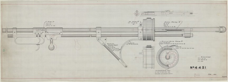
The magazine appears to hold at least 13 or more rounds according to the available patent and Winchester’s engineering drawings. The magazine is fixed in place and rounds appear to have been fed into it through the loading/ejection port on the left side of the weapon. This would have also put spent cases being ejected right next to the user’s neck. Curtis’ patent explains that the magazine has a spring inside which has a length of string attached to the top of it which the user can pull back to depress it and allow cartridges to be loaded into the drum. The magazine has a single stack or loop of cartridges. Once loaded the string can be released, allowing the magazine spring to push rounds into the action.
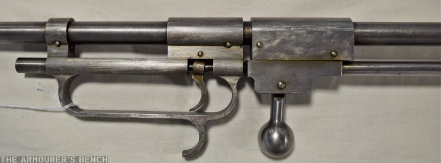
Close up of the left side of the Curtis’ trigger, bolt assembly and hand loop (Photo by Matthew Moss, courtesy of the Cody Firearms Museum)
The Curtis rifle’s action appears to lock at the front of the weapon with the bolt handle acting on a hinged, spring-loaded, locking piece or flapper which dropped into place when locked. To unlock the action the bolt handle was sharply pulled to the rear which pushed the locking piece out of engagement and unlocked the action allowing the operating rod to be cycled.
The weapon’s chamber appears to be just forward of the centre of the drum magazine with the striker assembly located behind it. To operate Curtis’ rifle the magazine was loaded and then the user had to unlock the action by pulling the bolt handle backwards. This then allowed the operating rod to be pulled backwards, like a pump action, which pushed the bolt and striker assembly to the rear, cocking the striker, the bolt handle was then returned forward and locked back into position. This chambered a round ready to be fired.
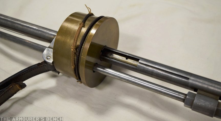
Close up of the Curtis’ brass drum magazine and loading/ejection port (Photo by Matthew Moss, courtesy of the Cody Firearms Museum)
The trigger at the front of the firearm is connected to the striker assembly by a long length of wire. When pulled the wire becomes taught and trips a sear to release the striker, firing the weapon.
Originally Curtis’ patent describes how ‘small punches’ on the bolt face would pierce the cartridge base during firing to enable the spent case to be extracted once the action was cycled. From Winchester’s engineering drawings, however, it appears they replaced this with a more reliable and conventional extractor at the 7 o’clock position of the bolt face.
Given that the weapon would have fired black powder cartridges it is unclear how well the rifle would have faired with sustained firing. The drum magazine would have been susceptible to jamming as a result of powder fouling. This, however, would not have been an issue for Winchester later version of the rifle.
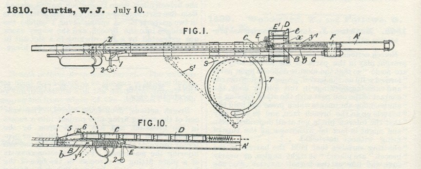
Detail of Fig.1 & Fig.10 from Curtis’ 1866 patent (courtesy of Research Press)
But the Curtis has one more interesting surprise. The original 1866 patent also includes what might be one of the earliest descriptions of a gas operated firearm. One of the most fascinating sections of Curtis’ original patent details how the rifle might have been adapted for gas operation:
“An arrangement is shown in Fig.10, in which the rod G is dispensed with; in this case the barrel may be shorter, not projecting beyond the shoulder; the butt is similar. The breech may be opened automatically by the powder gases, which pass by an opening in the barrel to a cylinder with which works a breech operating plunger.”
Curtis does not go into further detail but he is clearly describing a piston-driven, gas operated system. The patent drawing also depicts an alternative tube magazine instead of the drum magazine.
It is unknown if Curtis ever put his theory to the test and developed his gas system idea further. It is tempting to wonder if, in 1895 when Winchester were assembling their model of the Curtis, if John Browning or William Mason, who were also developing their own gas operated systems at the time, were aware of Curtis’ idea from 30 years earlier. As such Curtis’, admittedly vague, gas system pre-dates the first patents on gas operation by just under 20 years.
If you enjoyed the video and this article please consider supporting our work here.
Specifications:
Action: Slide action
Calibre: .32 Winchester Centre Fire
Feed: ~12 round drum magazine
My thanks to the Cody Firearms Museum at the Buffalo Bill Center of the West for allowing me to examine and film the Curtis. Special thanks to the CFM’s assistant curator Danny Michael for making extra time to open up the case where the rifle Curtis is on display so we could examine it and for also sharing Winchester’s technical drawings and other records.
Thanks also to David Minshall of Research Press.co.uk for his assistance finding Curtis’ original British patent abridgement and to John Walter for digging up some additional information about Curtis’ life.
Bibliography:
‘Winchester Suit Decided’, The Times (Philadelphia), 27th June, 1897
‘Recollections of the Forming of the Pugsley & Winchester Gun Collections: A Talk Given by Mr. Edwin Pugsley at the New Haven Meeting of the AS of AC’, September, 1955.
During my recent research trip to the US I was lucky enough to handle and examine a lot of very interesting firearms. This short video is a bonus, while we were opening one of the cases at the Cody Firearms Museum to examine another firearm (that video is coming soon) I noticed a sectioned British Pattern 14 rifle, made by Winchester for the British government during the First World War. It was too good an opportunity to pass up so I filmed this quick video taking a look at the P14’s internals.
The P14 would go on to be the basis of the US M1917 rifle built by Winchester, Remington and Eddystone.
Cutaway of a Winchester-made Pattern 14, note the rear volley sight and sectioned magazine and chamber (Matthew Moss)
The cutaway shows the internals of the rifle’s actions as well as the barrel, chamber and magazine. It was cool to see a cutaway of the P14 up close and I couldn’t resist grabbing some footage.
My thanks to the Cody Firearms Museum, at the Buffalo Bill Center of the West, for allowing me access to their collection. You can find out more about the CFM here.