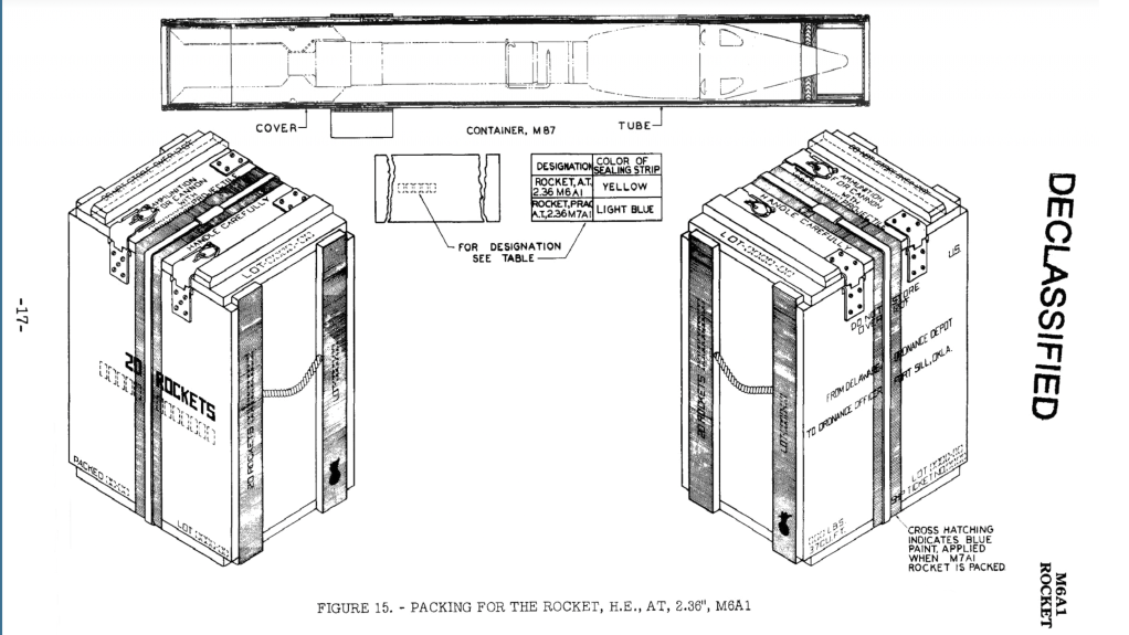
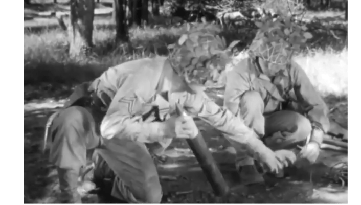
I recently came across an interesting segment in a January 1945 US Army Combat Bulletin newsreel. It showed men of B Company of the 238th Combat Engineers setting up improvised anti-tank mines in Belgium. The mines were fashioned from Bazooka rockets!
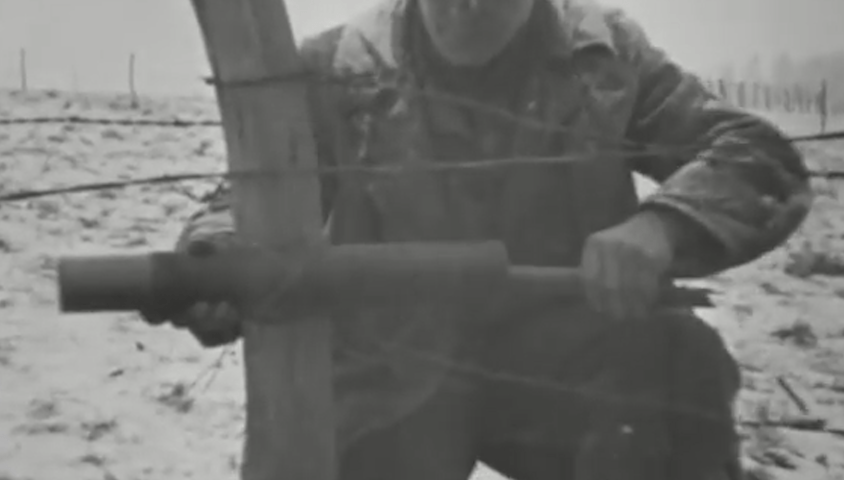
This is a relatively little-known application for the Bazooka’s rockets but a really interesting field expediency. The footage shows engineers cutting the cardboard tubes the Bazooka’s rockets were carried in, down and attaching them to a fence post. Essentially setting up an off-route mine or IED. The engineers run a wire back to cover for remote detonation with some batteries.

While these seems quite ad hoc it was a secondary use for the Rocket Launcher’s ammunition which was laid down in the Bazooka’s 1944 basic field manual. It doesn’t appear in the 1943 technical manual for the M1A1 launcher at all but the 1944 manual explains that
“In addition to its use as a projectile when fired from the launcher, the rocket may be prepared for firing electrically and used as an improvised anti-tank mine.”
This improvised method of use was also demonstrated in a training film for the Rocket Launcher, a Bazooka team are seen digging a pit in a road and burying a rocket in its makeshift launcher just as laid down in the manual. The training film explains it best…
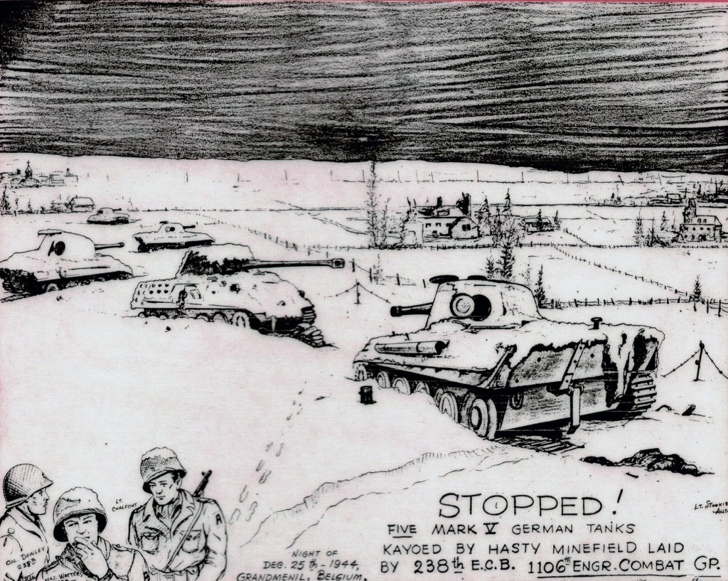
The 238th Combat Engineer battalion fought in the Battle of the Bulge and received a commendation from Major General Matthew B. Ridgeway, commander of XVIII Corps, for helping to establish a line of defence against the German offensive. The commendation read:
“The work of the 238th Engineer Combat Battalion in the construction of the initial barrier in the vicinity of Manhay was outstanding and materially assisted the Corps in holding off the attack of the enemy in that area.”
Whether this technique of improvising a mine from the rockets was used during the battle is unclear but I found the footage of the engineers demonstrating the set up fascinating. Its always interesting to see suggestions from manuals and training films put into action in the field so I was excited to come across this footage.
If you enjoyed this video and article please consider supporting our work here. We have some great perks available for Patreon Supporters – including custom stickers and early access to videos! Thank you for your support!
Bibliography:
238th Combat Engineer Battalion Association (source)
The Ardennes: Battle of the Bulge, H.C. Cole, 1965, (source)
Footage:
The Anti-Tank Rocket M6” 1943 US Army Training Film; M1 & M1A1 Bazookas, War Department
Combat Bulletin No.39, War Department