Our thanks to the collection that holds the G11 for the privileged and nerve-wracking opportunity to field strip it and take a look inside. If you’d like to know more about the history of the G11’s development you can check out our video and full blog on it here. Vic has done a great series of videos looking at the G11 and the other prototype rifles from the US Army’s abortive Advanced Combat Rifle trials – you can find those here.
In this blog we’ll take a closer look at some of the G11’s components, for a demonstration of dissassembly and and explanation of how the rifle works in principal check out the video above.
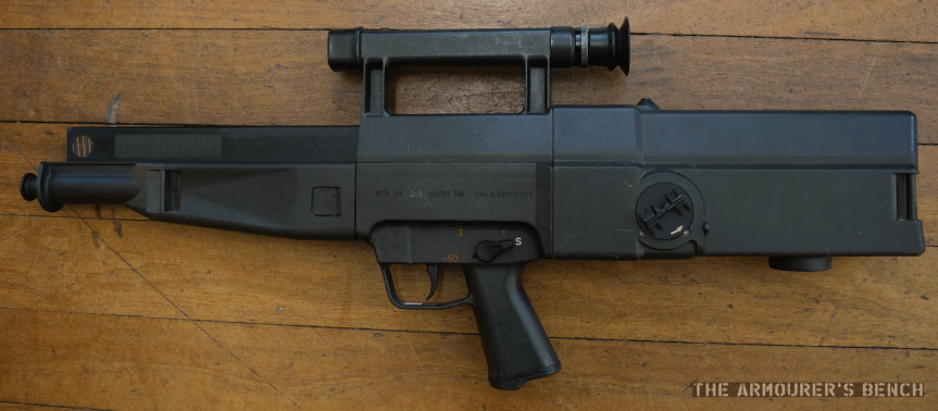
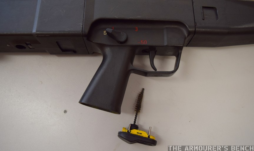
Firstly, lets take a look at the exterior of the rifle. The weapon has a box-like polymer coated outer shell. The shell is made up of three parts, with the butt assembly and forend locking into the centre assembly which includes the pistol grip, trigger mechanism and optical sight. The forend and butt are locked into the centre assembly by plastic locking tabs. While stiff and somewhat difficult to depress the tabs are reportedly prone to breaking.
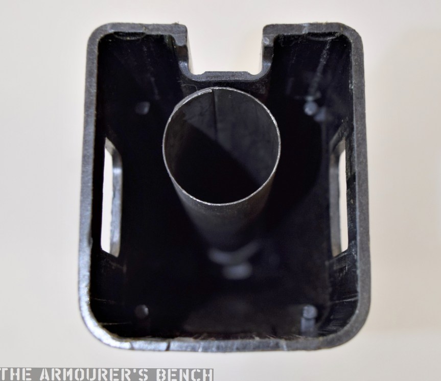
Before we look at the G11’s internals lets take a look at the shell components. Here we can see the inside of the forend, we can see a metal (aluminium I believe) barrel tube into which the barrel slides.
Below is a photograph of the rear of the centre assembly looking forward, the small white circle (sadly slightly out of focus) is the bushing the barrel protrudes through into the forend.

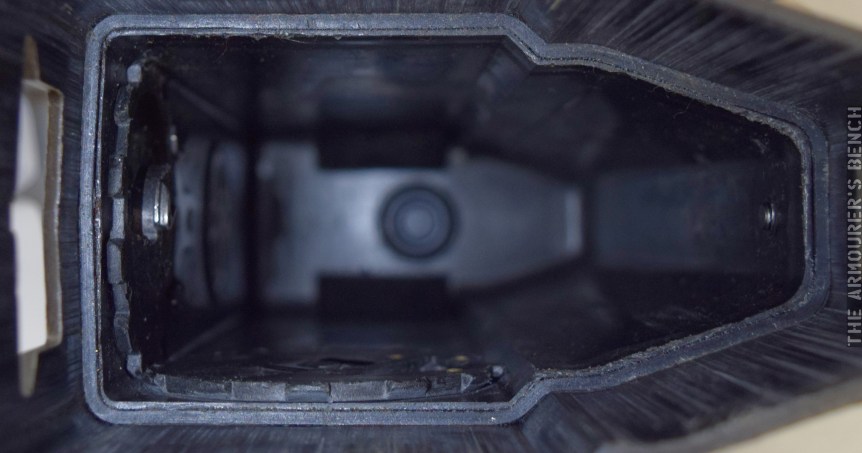
Next we have a view of the inside of the rifle’s butt assembly. Note the scuff marks on the inside where the centre assembly has scrapped the plastic. We can also see the locking tab windows which are on the top and bottom of the butt.
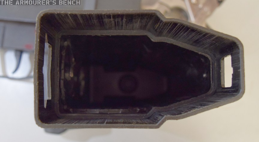
Inside the butt we can see the ‘toothed wheel’ and ‘sealing gear’ which are turned when the cocking piece is rotated. These plastic pieces act directly on the action. Behind that is the gas escape valve, which will tap off excess gas if over pressure problems occur with the rifle.
The first step to disassembling the G11 is ensuring the weapon is clear by pushing the cleaning brush up into the breech.
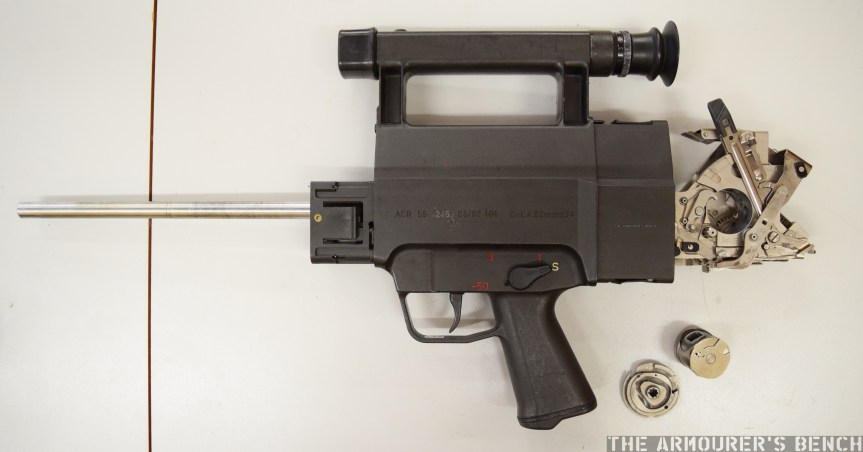
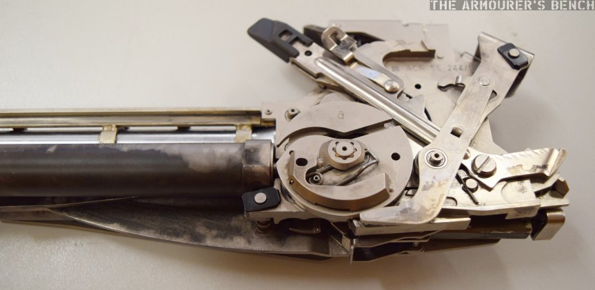
Lets now take a look at the rifle’s action up close, below we can see the G11 with its forend and butt assembly removed. Next to it is the breech cylinder and control disk.
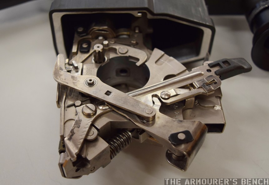
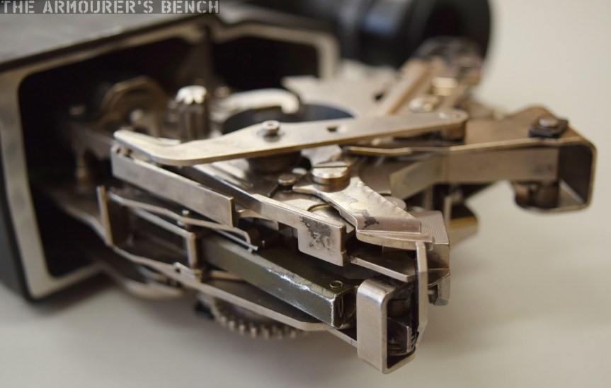
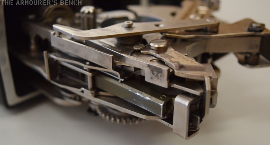
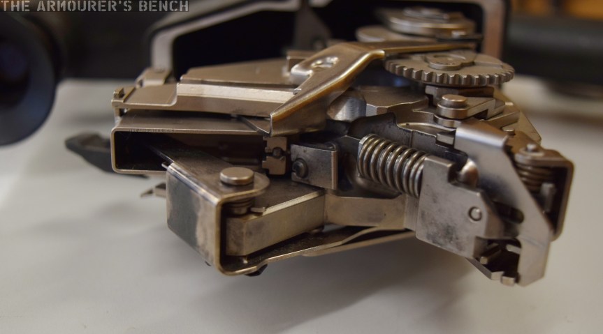
Here are some photos of the action from various angles:

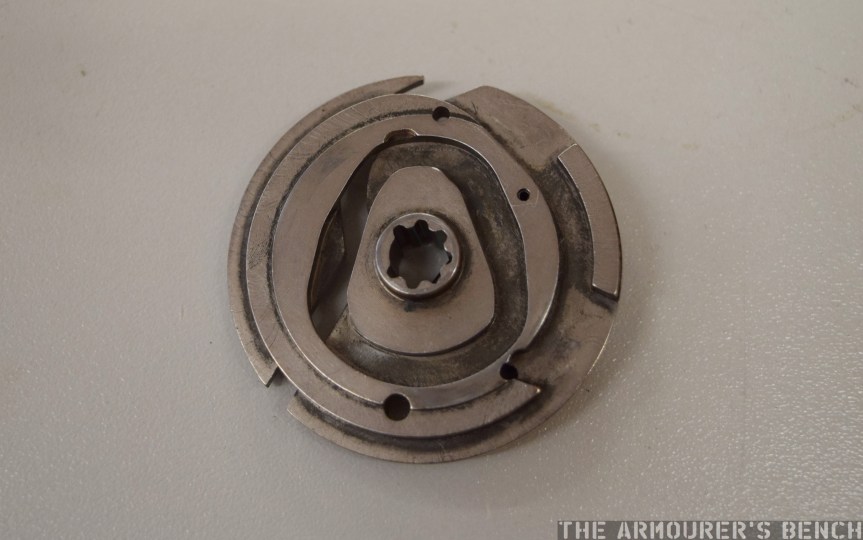
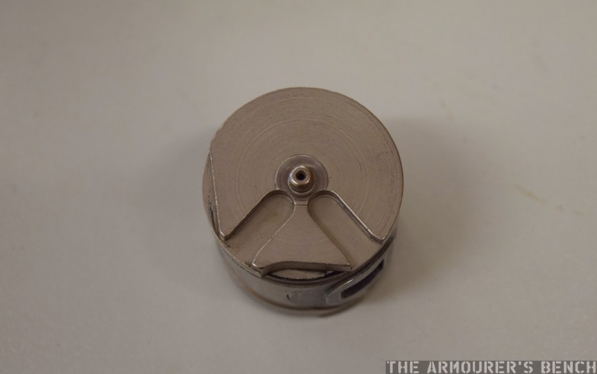
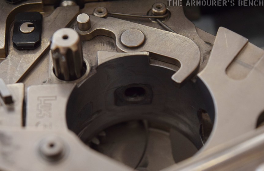
Here’s some close ups of the breech cylinder and control disk:


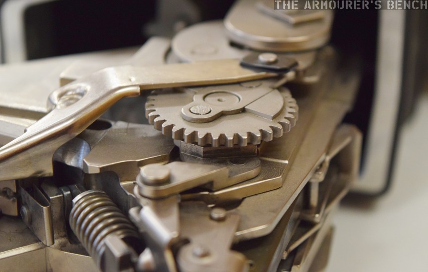
Here are some close ups of the various parts of the action:
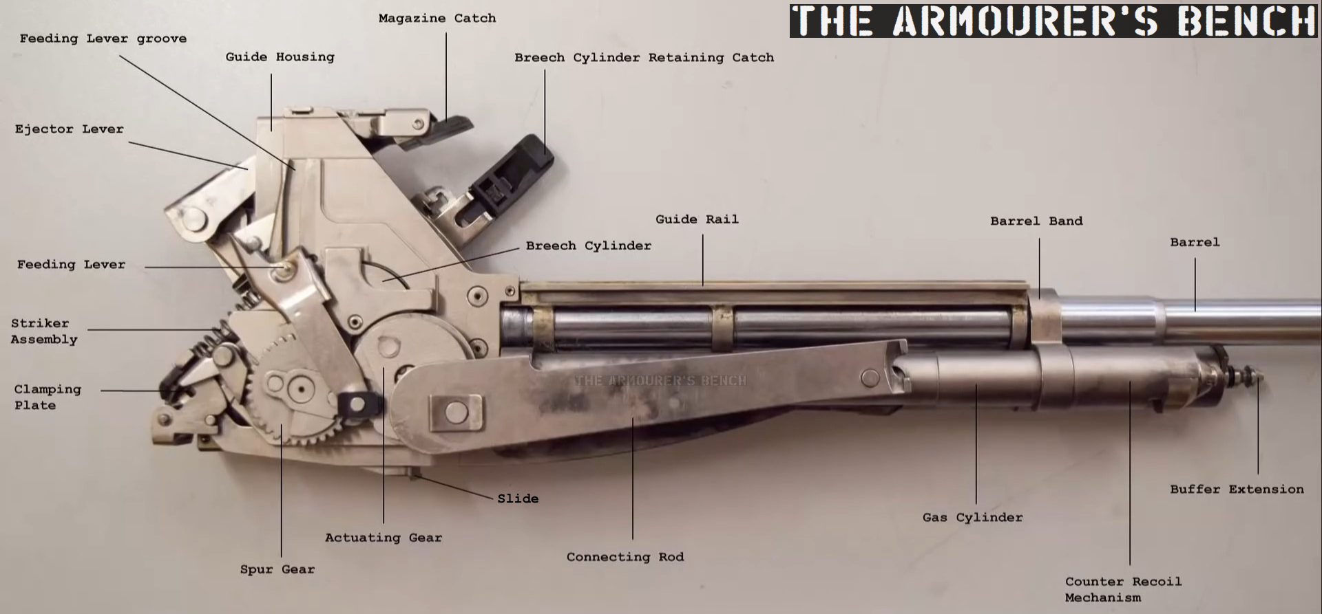
According to the 1989 armourer’s manual, provided for the ACR trials, the G11 is made up of a total of nearly 450 individual parts. 144 of those make up the G11’s breech assembly.
With the breech and barrel assembly removed from the centre assembly here’s a diagram I put together showing most of the component parts of the G11’s action:
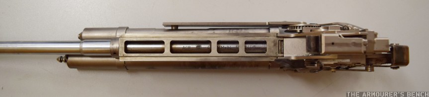
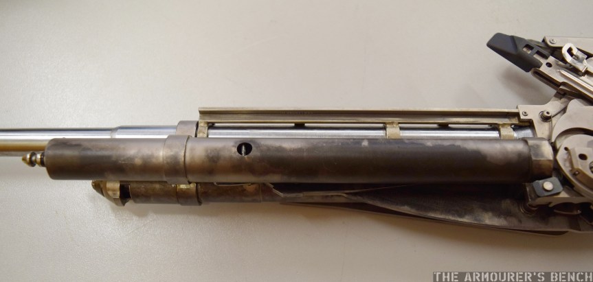
Next lets take a look at the G11’s barrel assembly with its recoil management system and gas piston:
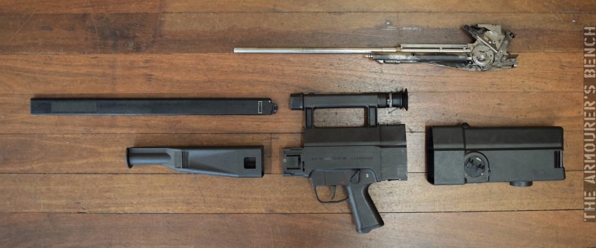
Finally, here’s a photo of the G11 broken down into its major component assemblies: magazine, forend, centre assembly breech & barrel assembly and butt stock:
If you enjoyed the video and this article please consider supporting our work here.
Bibliography
HK G11- ACR. Armourer’s Manual for Maintenance of Repair of Rifle, 4.92mm, ACR, March 1989 (source)
‘Rifle, 4.92mm, ACR’ Operator’s Manual (source)
Please do not reproduce photographs taken by Matthew Moss without permission or credit. ©The Armourer’s Bench, 2018.
Discover more from The Armourers Bench
Subscribe to get the latest posts sent to your email.

slot machines for home entertainment monopoly slots
LikeLike