US M1917 Light Tank

Continuing our series looking at US tanks of World War One, in which we have already taken a look at the Ford M1918 3-Ton Tank, in this video/article we will take a look at the M1917 Light Tank. 

The US Army entered the Great War with no tanks or experience in armoured warfare. When the American Expeditionary Force’s Tank Corps was formed in early 1918, it was equipped with French and British tanks. With plans to rapidly expand the US Tank Corps with battalions training in the US, France and Britain, a large number of tanks would be needed. The corps trained with the French Renault FT light tank and the British MkV but with French production stretched to capacity they could not hope to provide the US with the tanks it was expected to need for operations during 1919.

edpeQ1dt0HpgxWcms3dTwKtiCZ55JatQS7c34nfy82w
Renault FT on the Western Front (US National Archives)

As a result the US negotiated with France for a license to produce the FT in the US, commissioned a smaller 3-ton light tank from Ford and entered into an agreement with Britain to build a new heavy tank – the MkVIII. The American-made FTs were designated the Model 1917 6-ton light tank. 4,400 were ordered, with deliveries to begin in April 1918. The Ordnance Department finalised the M1917s design and contracted a number of private companies to build the tanks.

Delays in production, however, meant that the first American tanks were completed in October 1918, and none of the M1917s reached the Western Front before the war ended. As a result, the primary US tank of the war was the original French Renault FT, revolutionary for its turret which could rotate 360-degrees and its rear-mounted engine. It was cheaper to manufacture than the heavier British tanks and could be transported by lorries behind the lines. The FT equipped the 1st Provisional Tank Brigade, what would become the 304th Tank Brigade, commanded by Lt. Colonel George S. Patton. The American FT’s saw action for the in September 1918, at the Battle of St. Mihiel.

165-WW-313A-058
US-operated Renault FTs on the Western Front (US National Archives)

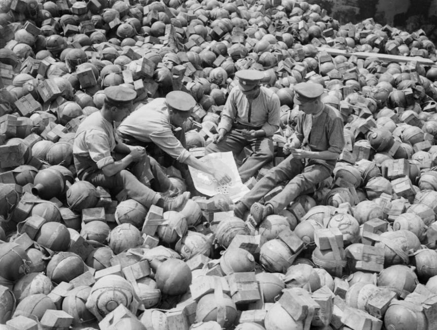
144 US FT’s took part in the battle and both the tanks and crews performed well. The Five of Hearts, a 37mm-armed FT with the 344th Tank Battalion took part in the Meuse-Argonne offensive and while making an isolated attack on German positions in support of bogged down US Infantry, the tank was immobilised and its gun mantle jammed by enemy small arms fire. The tank’s commander Sergeant Arthur Snyder recalled:

“My wounded driver kept filling pistol clips and I produced as much fire as possible with our pistols and the crippled 37mm. I paid more attention to the volume of fire than its accuracy for I fear the enemy would close in if the volume diminished. Three machine guns were set up at very close range, but just out of range of our piece with its limited elevation. The fragmentation of our shells did afford some protection but I could not train this fire on the German field piece. The constant hammering of these machine guns at close range was terrific. The hinges on the doors could not stand up under it for long, but it was the mushroom ventilator on top of the turret that gave way. I was hit in the back of my head with fragments of it and bullet splinters.”

Luckily for Snyder the German infantry made no attempt to rush the tank, content to pepper it from a distance, and they quickly retreated when infantry from the 16th Infantry arrived.

In terms of protection Snyder felt that “the armor plate on those old French Renaults was good, but when you came to close quarters the splinters from bullets hitting around the vision slits did considerable damage.” Two of Snyder’s drivers were badly wounded one by bullet splash splinters and the other in the throat.

165-WW-313A-055 - Copy.jpg
A newly completed M1917 at the Van Dorn Iron Works, 1919 (US National Archives)

The M1917 was manufactured by the Van Dorn Iron Works, the Maxwell Motor Co., and the C.L. Best Co. Of the original wartime order for over 4,000 tanks, in total just 952 M1917s were produced. 375 of these are believed to have been equipped with 37mm M1916 cannons, while 526 armed with Marlin M1917 tank machine guns. The remaining 50 were outfitted as unarmed signal tanks.

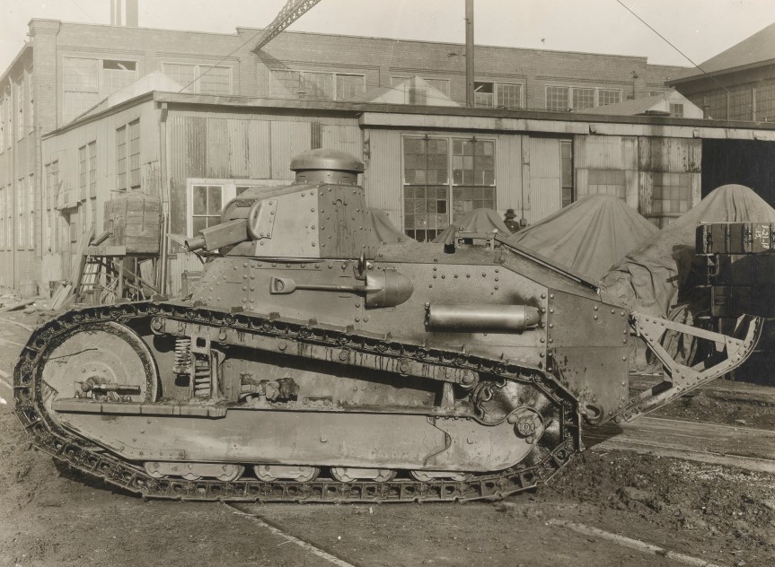
The M1917 has a number of small differences from the FT. Its exhaust is located on left rather than right side of the tank. A new US-designed gun mount and mantlet was used. Solid steel idler wheels at the front of the tank rather than the spoked type used by the French. Additional vision slits for the driver were added and a bulkhead sectioned off the engine from the cab. Like their French cousins the M1917 was manned by a two-man crew, the driver and the commander who also acted as loader and gunner.

165-WW-385F-004 - Copy.jpg
Marlin M1917 Tank Machine Gun (US National Archives)

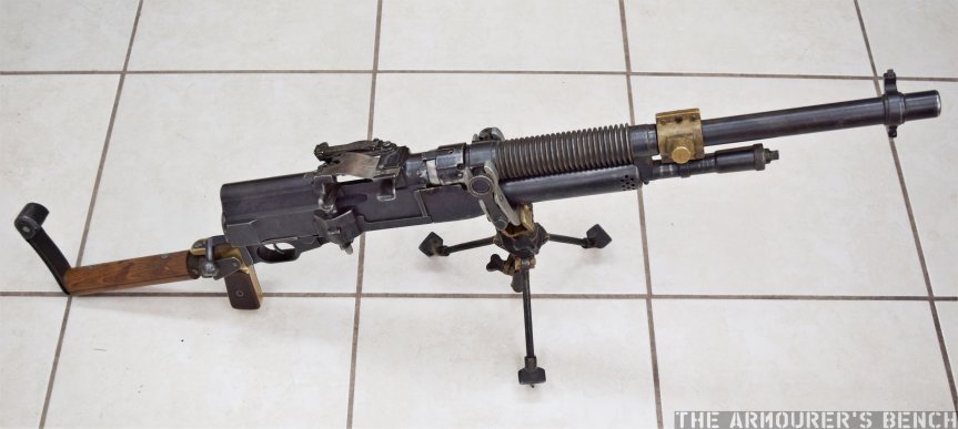
A different, American-made, engine – a water-cooled 4 cylinder engine built by the Buda Engine company was used. Developing 42 horsepower, it had more torque than its French counterpart but was no faster, with a top speed of between just 6 – 8 miles per hour. The tank weighed just over 7 US tons and was 16.5 feet long and 7ft 7” tall. Its armour was 0.25″ to 0.6″ (6.35mm to 15.25mm) thick – slightly thinner than its French counterpart. The majority of the tanks were armed with machine guns, using the .30 calibre M1917 Marlin tank machine gun, rather than the French Hotchkiss. The ‘male’ or cannon armed tanks had a 37mm gun and carried more than 230 shells for the gun. The Marlin was later supplanted by the early iteration of the M1919 Browning tank machine gun. 50 command and signals tanks were also built, these unarmed tanks were similar to the French TSF (télégraphie sans fil) and fitted with a wireless radio.

165-WW-313A-021 - Copy.jpg
An M1917 climbing Pikes Peak, April 1919 (US National Archives)

Perhaps the M1917s most impressive feat stemmed from a publicity stunt in April 1919, when a M1917 climbed Pikes Peak, a mountain in Colorado. At the time the road up Pikes Peak was said to be the ‘World’s Highest Motor Drive’, a single tank was driven up the mountain as part of fund raising efforts for the fifth, and final, round of Liberty Bond sales, which hoped to raise $4.5 billion from the sale of government bonds. We’ll have a separate looking at this exploit at a later date!

None of the M1917s reached the frontline but many were used a props for selling war bonds – in this photo dated April 1918, a platoon of M1917s is seen after they arrived at Camp Meritt by train, they are about to be painted up in camouflage for a Victory Loan parade in New York.

111-SC-53605 - Copy.jpg
US M1917s exercising with infantry, at Camp Meade, 1920 (US National Archives)

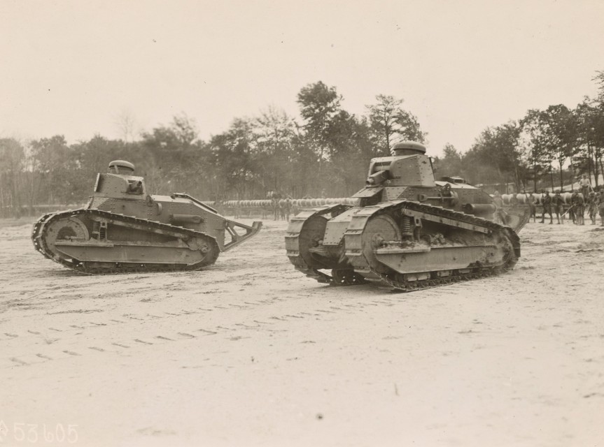
After the war the M1917, along with just over 200 French-made FTs brought back from France, formed the backbone of the US Tank Corps. In these photos we can see several tanks taking part in a mock-battle with supporting infantry at Camp Meade in May 1919. This photo show men learning to service their vehicles at Camp Meade, in December 1919.

M1917s arrive in canada
Obsolete M1917s arriving in Canada in 1941 (Library & Archives Canada)

But by 1921, the Corps had lost its independence and been all but disbanded with the Infantry given control of America’s tank force. A handful of the M1917s were deployed briefly overseas with the USMC, during the 1920s, but the M1917 was resigned to training as it became increasingly obsolete. They were finally removed from service in the mid-1930s. When World War Two broke out the remaining M1917s were sold to Canada and were reportedly used to help train the Royal Canadian Armoured Corps before many of them were finally scrapped.


If you enjoyed the video and this article please consider supporting our work here. We have some great perks available for Patreon Supporters.


Bibliography:

Footage courtesy of the US National Archives (source)
Camp Colt to Desert Storm: The History of U.S. Armored Forces
, G.F. Hofmann & D.A. Starry (1999)
Tanks: 100 Years of Evolution, R. Ogorkiewicz (2015)
Light Tank M1917, Tank Encylopedia, C. Moore, (source)
The Saga of the Five of Hearts, Armor, July-Aug. 1988, Maj. Gen. W.R. Kraft Jr. (source)

Vickers Gun Disassembly

The Vickers Gun is an iconic weapon, developed from the Maxim and adopted by the British in 1912. It served for over 50 years in conflicts all around the world. In this video, we’re lucky enough to have Richard Fisher of the Vickers Machine Gun Collection and Research Association shows us how to disassemble a the gun and talk us through its internals.

Big thank you to Rich for taking the time to help with this video and provide the voice over explaining the process! We’ll have more videos on the Vickers Gun in the future! Check out Richard’s work over on the Vickers Machine Gun Collection and Research Association’s site here.

I’ll let Rich explain the disassembly process in real time in the video but here are a couple of photographs of the gun disassembled:

DSC_0371
The Vickers gun field stripped (Matthew Moss)

This is the gun in its fully field stripped condition, with lock still assembled, but with its fusee spring and cover off and its barrel and action removed. Just below the barrel is the feed block.

Here’s the Vickers Gun’s lock disassembled into its 14 component parts:

DSC_0363
The gun’s disassembled lock (Matthew Moss)

This photo gives us a good look inside the receiver with the barrel, action and side plates removed, The spade grip assembly simply folds down to allow the action and barrel to be slide out of the gun.

DSC_0366
Once the action and barrel is removed you can look straight through the receiver and down through the water jacket (Matthew Moss)

Finally, here’s the gun reassembled and ready for action.

DSC_0353
The gun fully reassembled (Matthew Moss)

Thanks again to Richard for his help with this video, it was great to collaborate and hopefully we’ll have more videos with Rich in the future.  Please check out the Vickers Machine Gun Collection & Research Association’s site to find out more about what they do. They have some wonderful resources, including a comprehensive collection of manuals, for not just the Vickers but also the wider British Army from the past 100 years. You can also order copies of the brilliant instructional posters which were featured in the video over on the the associations website too!

If you enjoyed the video and this article please consider supporting our work here. We have some great new perks available for Patreon Supporters.


WW1 2-Inch Trench Mortar

The British Army entered the First World War with very few mortars, and certainly none at the battalion level. As the stalemate of trench warfare set in and the effectiveness of enemy mortars became clear it was decided that trench mortars of various sizes would be needed.

Nicknamed ‘plum pudding’ or ‘toffee apple’ mortars after their projectile’s characteristic shape, the 2 inch Medium Mortar or 2 inch Trench Howitzer, was one of Britain’s first effective light trench mortars to be introduced.

tilt_h13_2_inch_mortar
Right-side view of the 2in Trench Mortar (Matthew Moss)

Trench mortars were the army’s most forward artillery, right up on the front line. These short range weapons were able to throw large, high explosive projectiles, short distances across No Man’s Land at the enemy trench system opposite. The 2 inch mortar was considered accurate out to 350 yards with a maximum effective range out to just under 600 yards.

Introduced in 1915, the 2 inch mortar was originally crewed by men taken from the battalion it was stationed with, along with some specialists from the Royal Artillery. However, with the introduction of the 3 inch Stokes mortar which was operated by the infantry themselves the 2 inch mortars became the sole responsibility of the Royal Field Artillery.

Mesopatamia 4
A young gunner loads a 2in spigot mortar bomb into his mortar (Imperial War Museum)

Mortar positions were often in secondary trenches just behind the infantry’s frontline. This was to help protect the infantry from potential counter-battery fire. The trench mortars were often deployed to sectors to provide counter battery fire against German minenwerfers or in the run up to an offensive or local action. A British Army report on artillery use, drawn up in February 1917, noted that “Owing to their liability to be destroyed by hostile artillery fire it may often be advisable to defer opening fire with these mortars till the last day of bombardment.” The mortars were also tasked with keeping gaps made in the wire clear and with supporting any feint attacks made by infantry during gaps in the bombardment running up to a larger offensive.

Llewelyn Wyn Griffith, a captain with the 15th Royal Welch Fusiliers and later a novelist, recalled in his war memoir:

“At night a trench mortar officer set his guns in a derelict trench about twenty yards behind the line and carried up his ammunition, heavy globes of iron with a little cylindrical projection like a broken handle. In the morning I moved the men from the bays between the trench mortars and their target, to lighten the risk of loss from retaliatory fire.”

Sometimes the width of No Man’s Land required saps to be cut extending out from the frontline so the mortar rounds didn’t fall short. The 50 lb lollipop-like projectile had a maximum effective range of 570 yards (depending on the size of cordite charge used), and could create a crater 5 feet deep and 14 feet wide. The ideal mortar position was a 6 feet wide by 9 feet deep sandbagged pit with the weapon’s heavy wooden bed at the bottom and room for the crew to load the mortar.

Mesopatamia 1
A British 2in Mortar position in Mesopotamia, note the ignitor’s breech is open (Imperial War Museum)

Crews could manage to fire approximately once every two minutes. Much slower than the lighter 3 inch Stokes Mortar and but faster than the heavy 9.45 inch Heavy Mortar. The mortar comprising of just its tube, bed, stand and ignition system weighed 320 lbs (145kg), not including the accompanying tools and the Temple silencer system which could be fitted (which weighed 47 lbs or 21 kg alone).

Typically manned by a 5 man mortar crew comprising of an NCO, gunners, and ammunition bearers. To operate the 2 inch mortar a cordite charge was first placed down the tube, the projectile’s shaft was then inserted on top of the charge, the projectile’s fuse was set and checked and a new blank cartridge chambered in the ignition system. The crew then got clear of the weapon and pulled the lanyard to fire the mortar. To reload the crew ran a clearing stick down the tube and then repeated the loading process.

DSC_0790.jpg
The business end, a view down the length of the mortar (Matthew Moss)

Interestingly, the 2 inch Medium Mortar, like the larger 9.45 inch Heavy Mortar used a cut-down rifle, which screwed into the ‘breech’ end of the mortar tube. This particular mortar has an 1894-dated cut down Lee-Enfield MkI as its ignition system, the cutdown rifle has a wooden insert in its magazine well but it still has its rear volley sight attached. This reusable system replaced the T-tube Friction ignitor, which was in high demand by Britain’s bigger guns. The Lee-Enfield-based system enabled the cordite propellant charges to be ignited by a blank .303 round instead. The rifle’s trigger was pulled with a lanyard from nearby cover. These cutdown ignitor rifle are sometimes confused for Obrez-style Lee-Enfields.

DSC_0787
A close up look at the 2in Mortar’s SMLE ignitor (Matthew Moss)

The weight of the cordite charge used dictated the range while a variety of different fuses were used with the projectiles, these screwed into the nose of the bomb. The sphere was about 9.3 inches in diameter with a 2 inch thread for the fuse at its head and a cup for the 22 inch long, 2 inch thick solid cast iron stick or spigot at its base. The sphere was filled with high explosive (Amatol or Ammonal). The high explosive bombs were painted white with a green or pink stripe around their middle.

They were often deployed in batteries of four with three Royal Field Artillery medium mortar batteries attached to each division. The mortars were predominantly tasked with cutting enemy barbed wire and destroying enemy trenches and forward positions, such a machine gun nests.

Royal Army Ordnance Corps playing cards 1916
Men of the Royal Army Ordnance Corps playing cards on a dump of trench mortar ammunition during Battle of the Somme (Imperial War Museum)

Captain Griffith described a battery of 2 inch mortars opening fire on enemy lines:

“A pop, and then a black ball went soaring up, spinning round as it went through the air slowly; more pops and more queer birds against the sky. A stutter of terrific detonations seems to shake the air and the ground, sandbags and bits of timber sailed up slowly and then fell in a calm deliberate way. In the silence that followed the explosions, an angry voice called out in English across No Man’s Land, ‘YOU BLOODY WELSH MURDERERS.’

The 2 inch medium mortar entered service in spring 1915 and remained in use into 1917 with British and Empire troops. It was used on the Western Front and in Mesopotamia. Over 800 were ordered initially with 675,000 bombs, many of the mortars were made in railway and agricultural machinery workshops, allowing larger factories to focus on more complex weapons. The 2 inch mortar was superseded by the larger bore Newton 6 inch mortar later in the war. Some of the remaining 2 inch projectiles were re-purposed as makeshift anti-tank mines, buried in no man’s land in anticipation of possible German tank attacks.

If you enjoyed the video and this article please consider supporting our work here.


Specifications:

Barrel Length: 3 feet (90cm)
Overall Weight: ~340lbs (154kg)
Projectile Types: High explosive & smoke
Projectile Weight: 51lbs (23kg)
Effective Range: 100-570 yards (90-520m)


Bibliography:

Primary Sources:

Field Artillery Notes No.7, US Army War College, (1917) (source)

‘Artillery in Offensive Operations’ GHQ Artillery Notes No. 4 January/February 1917 (source)

‘History of the Ministry of Munitions’, Volume XI, Part I Trench Warfare Supplies (1922)

Up to Mametz, L.W. Griffith,  (1931)

Newsreels:

The Battle of the Somme, 1916, Imperial War Museum (source)

With the Forces in Mesopotamia, 1917, Imperial War Museum (source)

Secondary Sources:

British Artillery 1914-1919. Field Army Artillery, D. Clarke, (2004)

Tommy, R. Holmes, (2004)

Live Fire: Hotchkiss Portative

The Hotchkiss Portative was one of the earliest light machine guns to see general service. It was used in action by a number of countries during the First World War, the example we’re examining today is a British Mk1 Hotchkiss Portative light machine gun.

British Portative’s were chambered in .303, and were initially issued to cavalry regiments as a light machine gun before arming some of Britain’s early tanks during World War One.

The gun was also known as the Hotchkiss Model 1909 and saw service with France, chambered in 8mm Lebel and the US, chambered in .30-06, where it was known as the 1909 Benét–Mercié Machine Rifle.

To cock the weapon the charging handle at the rear of the gun is turned to the unlocked position, at 12 o’clock, and pulled to the rear. It is then returned forward and the gun can be put in either safe, semi and full automatic.

DSC_0884
Mk1 Hotchkiss Portative Light Machine Gun (Matthew Moss)

Weighing around 25 lbs or 12kg the Portative was extremely heavy for a light machine gun. It had a small, unergonomic pistol grip to which the stock attached. This makes it difficult to hold the pistol grip and the stock attachment jabs into the hand during firing. The low position of the Hotchkiss’s stock provides a chin weld at best.

The Portative feeds from a 30-round metallic feed strip. Rounds are placed in the metallic strips and loaded into the weapon with the cartridges facing down. If not seated properly in the strip, vibration from firing can loosen the rounds causing them to fall out or induce jams. The strips were so fragile a sizer, used to realign bent or misshapen strips, was standard issue. Once the strip is empty it is thrown out of the gun with some force.

The Portative’s tripod while small and highly adjustable is poorly designed, it is unsuited to use in the field. As the gun is already top heavy and unbalanced, due to feeding from a side-loading ammunition strip, the gun has a tendency to topple over if not held firmly by the operator. This also complicates clearing jams and stopages.

We will have a full video and blog exploring the design, development and history of the Hotchkiss Portative in the future. My thanks to Chuck Kramer of Gun Lab for letting me shoot his Hotchkiss and helping with filming, check out his blog here.


If you enjoyed the video and this article please consider supporting our work here.